- 3 -
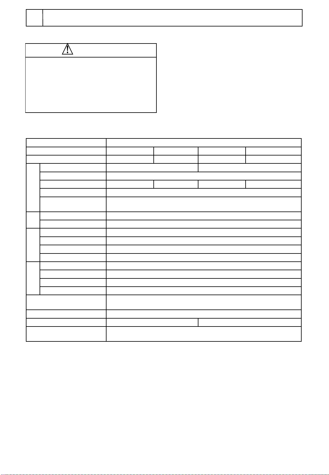
Product name Constant volume fluid supply pump(Peristaltic tube pump)
Model MP-2000A MP-2010A MP-2000B MP-2010B
Tube holding system Groove with a fixed width
Performance
Flow range 10~180 mL/h 0.5~9.0 mL/h 80~1450 mL/h 5.0~72.5 mL/h
Flow precision ±2% (Repetition precision: within ±1%)
Max. discharge pressure 147kPa(1.5kg/cm2)
Max. suction pressure 9.8kPa(0.1kg/cm2)
Viscosity and temperature
of solution Max.2Pa・s (2000cP) 0~60℃(Non-freezing)
Func-
tion
Rotation setting Volume setting
Fluid supply direction Normal/Reverse selectable
Configuration
Motor AC speed control & induction motor output: 15W
Driving circuit Speed feedback control
Tube case PVC resin
Safety function Thermal protector and fuse
Standards
Number of tubes to hook 1 tube
Number of tube case stages 1 stage
Usable tube material Silicon, Tygon® , Fluran® , PharMed®
Usable tube dia. I.D.:1.15mm×O.D.:3.2mm I.D.:3.7mm×O.D.:6.1mm
Operating environmental
temperature range 0~40℃(Non-condensing)
Ext. size[mm] ※1 120(137)W×130(152)D×177(190)H
Mass Approx.3.2kg
Power input and rated power
supply AC100V 50/60Hz 0.4A 40VA
※Performance has been measured at: room temperature of 20℃, rated source voltage, clean water, liquid
temperature of 20℃, back pressure of 0, a silicon tube(s) is used.
※Flow, flow precision, discharge pressure and other pressures will differ depending on the tube used.
※Discharge amount may be less when the viscosity of the solution exceeds 0.1Pa・s(100cp).
※1 Figures in ( ) shows a size including protrusions such as screws and knobs.
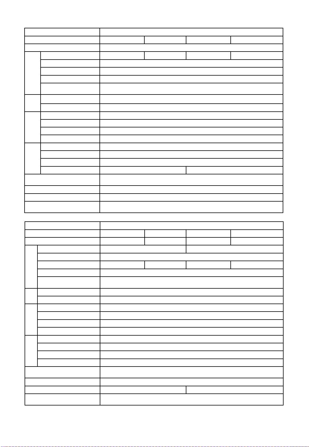
Product name Constant volume fluid supply pump(Peristaltic tube pump)
Model MP-2100 MP-2101 MP-2110 MP-2111
Tube holding system Screw-adjustable Spring type Screw-adjustable Spring type
Performance
Flow range 10~1450 mL/h×4 0.5~72.5 mL/h×4
Flow precision ±2% (Repetition precision: within ±1%)
Max. discharge pressure 196kPa(2kg/cm2) 98kPa(1kg/cm2) 196kPa(2kg/cm2) 98kPa(1kg/cm2)
Max. suction pressure 9.8kPa(0.1kg/cm2)
Viscosity and temperature of
solution Max.2Pa・s (2000cP) 0~60℃(Non-freezing)
Func-
tion
Rotation setting Volume setting
Fluid supply direction Normal/Reverse selectable
Configuration
Motor AC speed control & induction motor output: 15W
Driving circuit Speed feedback control
Tube case PET resin
Safety function Thermal protector and fuse
Standards
Number of tubes to hook 4 tubes
Number of tube case stages 2 stages
Usable tube material Silicon, Tygon® , Fluran® , PharMed®
Usable tube dia. O.D.: 3~6.1mm
Operating environmental
temperature range 0~40℃(Non-condensing)
Ext. size[mm] ※1 127(166)W×130(152)D×206(219)H
Mass Approx. 3.3kg Approx.3.4kg
Power input and rated power
supply AC100V 50/60Hz 0.4A 40VA