EZ-ACCESS Pathway Modular Gate User manual

Assembly Manual
Pathway® Modular Gate
For use with the Pathway® 3G Modular Ramp and Pathway Stair System
Gate shown on Pathway 3G Modular Ramp
Gate shown on Pathway Stair System
17025 04-03-17
LIFETIME WARRANTY. Please register at www.ezaccess.com/warranty-satisfaction.
© EZ-ACCESS®, a division of Homecare Products, Inc. All rights reserved.
All text and images contained in this document are proprietary and may not be shared, modified,
distributed, reproduced, or reused without the express written permission of EZ-ACCESS.
Click here to view detailed product descriptions and prices. Call 800-397-5899 to order today!

- 2 -
INTRODUCTION
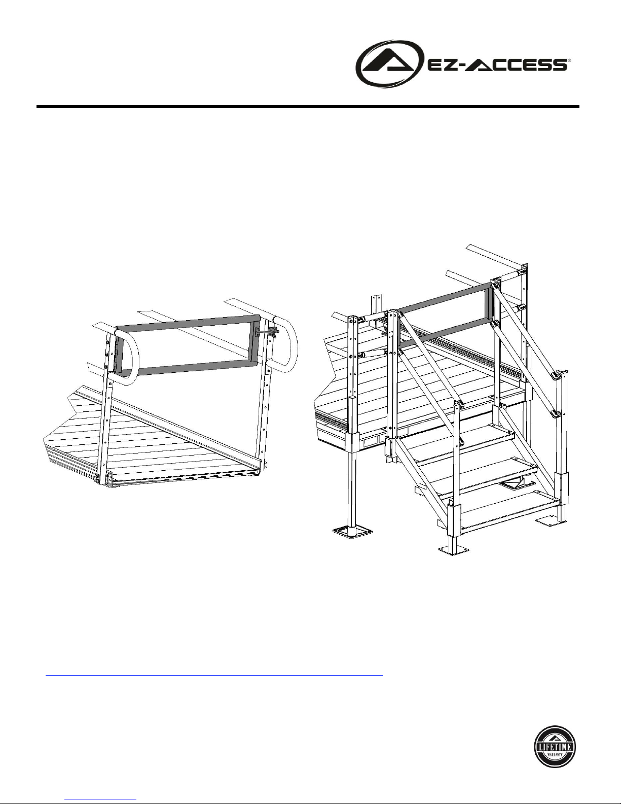
The Pathway®3G Modular Gate is universal and can be installed on a Pathway 3G Modular Ramp system or
at the top of a Pathway Stair System. Hinge can be installed on left or right. Before starting installation,
determine which side of the ramp or stair the hinge should be on and which direction the gate should swing
based on the specific installation and the end user’s desired placement.
ATTENTION INSTALLER AND END USER:
•For residential use only
•WARNING! THE PATHWAY 3G MODULAR GATE IS NOT DESIGNED TO BEAR WEIGHT. NEVER
HANG WEIGHT, OF ANY KIND, ON GATE, DAMAGE AND POSSIBLE INJURY COULD RESULT.
•Read and follow all labels, instructions, and warnings prior to assembly and use. For copies of complete
instructions, warnings, or for additional care, use, or safety information, call customer service at 1-800-
451-1903.
•Leave this ASSEMBLY MANUAL with the end user
•Do not use product until the installation is complete.
TOOLS TYPICALLY REQUIRED:
✓Rubber mallet
✓1/8″ drill bit
✓5/16” drill bit
✓1/4” nut driver
✓T-Handle Allen Wrench or similar tool
✓2 each 7/16” wrench, socket wrench, or adjustable wrench
✓Pencil or similar marker
WARNINGS
•Use caution at all times. Proper maintenance and upkeep to the system components is vital. NOTE: The term
“system” refers to the entire Pathway access system, including, but no limited to, gate, stairs, ramp, platform,
risers, handrails, supports, transition plates, landing pad, and any/all hardware and components.
•Regularly check that all parts are in good condition and check the system for damage. Ensure all fasteners and
locking mechanisms are in place and tightened. If any part of the system is damaged, loose, or missing; DO
NOT USE until repairs can be made by a certified installer or other qualified person.
•Do not use product for anything other than its intended purpose.
•Never play on or near the product.
•Inspect product for damaged or missing parts before each use. Never use a damaged or unstable product.
•Observe and avoid all pinch points.
•Do not tamper with or attempt to modify system components.
•Do not attach planters, lights, adornments, decorations, clothing, fabrics, or other ornamentals or furnishings.
•If user has a mobility concern, or otherwise has a weakened condition, use system only with a qualified helper.
•Metal conducts electricity. Do not use near exposed wiring or hang lights from system components.
•Only use components supplied or approved by manufacturer with system.
•Do not sit, stand, or climb on guards, handrails, or gates.
INSTALLATION TABLE OF CONTENTS
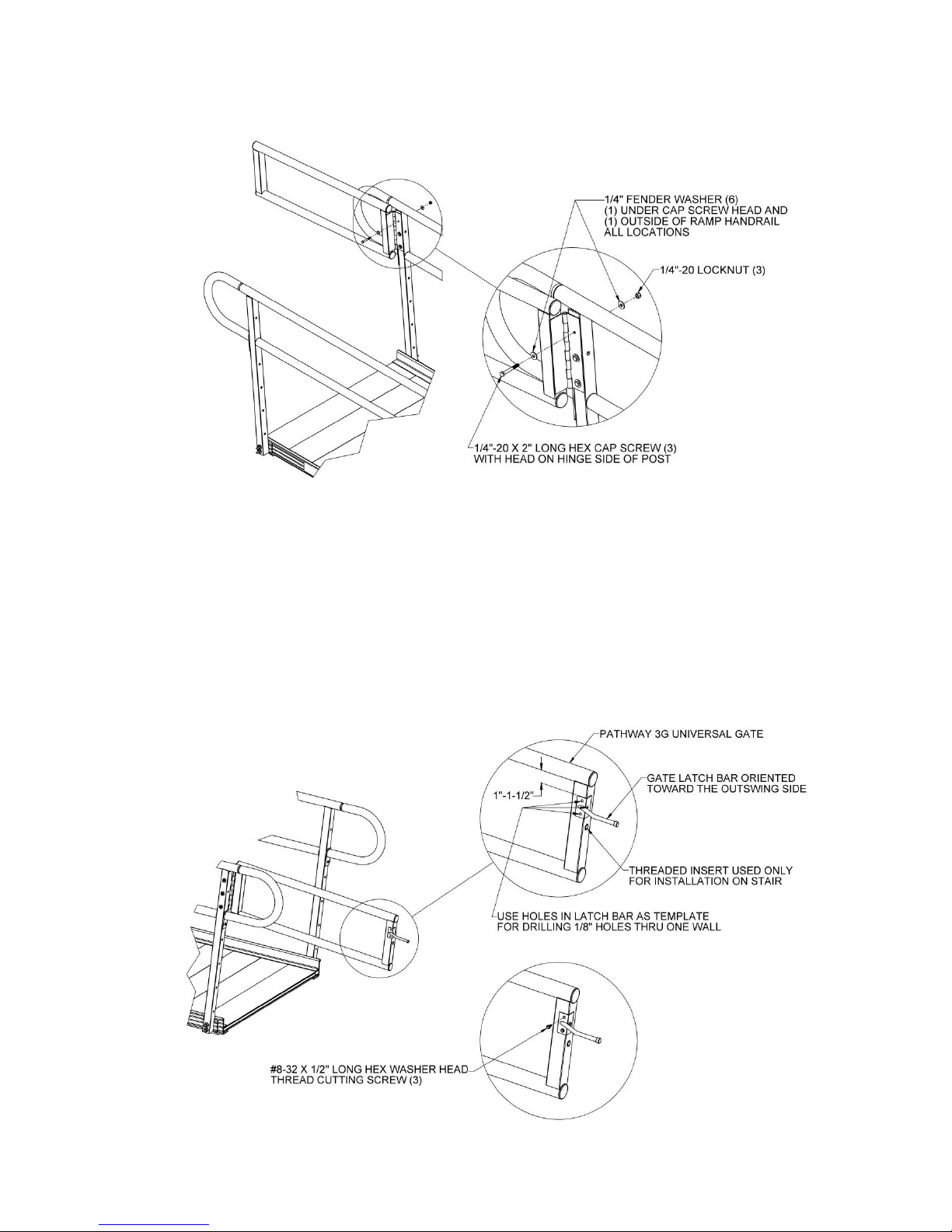
oInstalling Gate on A Pathway Modular Ramp Page 4
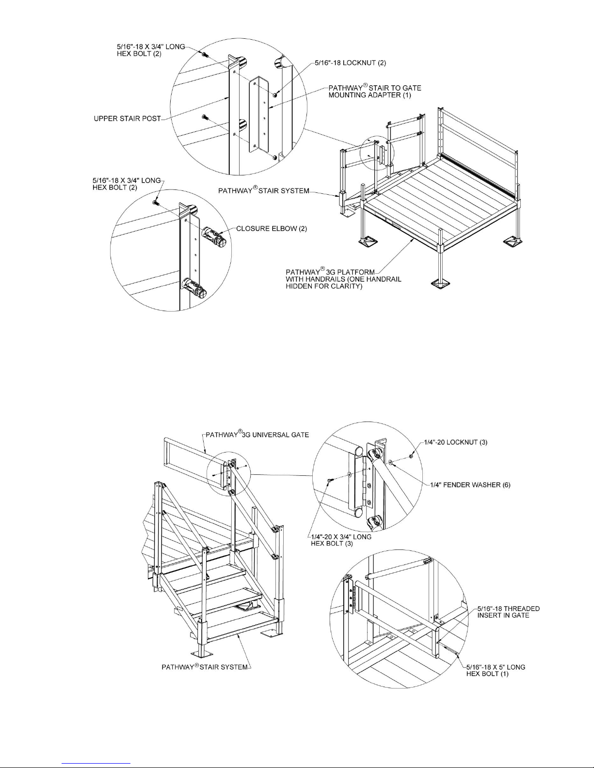
oInstalling Gate on A Pathway Stair System Page 6
oConnecting A Stair Post To A Platform Post Page 9

- 3 -
1. BASIC SYSTEM COMPONENTS
1.1. Because each installation is different, your system may or may not contain these basic components.
1.2. Ensure all components listed are present prior to assembly.
1.3. NOTE: Items not shown actual size.
PATHWAY 3G UNIVERSAL GATE
(QTY 1)
1/4”-20 X 2” LONG HEX CAP SCREW
(QTY 3)
#8-32 X 1/2” LONG HEX WASHER
HEAD THREAD CUTTING SCREW
(QTY 7)
1/4” -20 LOCKNUT (QTY 3)
1/4” FENDER WASHER (QTY 6)
GRAVITY LATCH (QTY 1)
Includes Latch & Latch Bar
1-1/2” DIAMETER TUBE PLUG
(QTY 4)
5/16”-18 X 5” HEX BOLT
(QTY 1)
1/4”-20 X 3/4” HEX BOLT
(QTY 3)
Used for Pathway Modular Stair
installation only
Used for Pathway Modular Stair
installation only
5/16”-18 X 3/4” HEX BOLT
(QTY 2)
5/16”-18 LOCKNUT
(QTY 2)
PATHWAY STAIR TO GATE
MOUNTING ADAPTER (QTY 1)
Used for Pathway Modular Stair
installation only
Used for Pathway Modular Stair
installation only
Used for Pathway Modular Stair
installation only

- 4 -
2. GETTING STARTED
2.1. Install the 1-1/2” diameter tube plugs into ends of the 1-1/2” diameter tubes on the gate. Use a rubber
mallet to tap plugs into place until fully engaged (FIG. 1).
FIG. 1
3. INSTALLING GATE ON A RAMP
3.1. Position the gate hinge against the ramp handrail post in the desired location. Position the gate so that
the upper gate tube aligns with the upper ramp handrail tube and the edge of the hinge is flush with the
edge of the ramp handrail post.
3.2. Use the holes in the hinge as a template and mark the locations with a pencil or similar marker. Drill
three 5/16” holes through the post at the marked locations (FIG. 2).
FIG. 2

- 5 -
3.3. Attach the gate to the ramp post using the 1/4”-20 x 2” long hex cap screws, 1/4”-20 locknuts and 1/4”
fender washers. Orient the hex cap screws with the head on the hinge side of the post and the washers
(FIG. 3).
FIG. 3
3.4. Remove the latch and latch bar from the bag containing the gravity latch and discard the included
screws (they will be replaced with the #8-32 x 1/2” long hex washer head screws).
3.5. Place the latch bar on the square tube opposite the gate hinge with the bar oriented toward the
outswing side of the gate and top of the mounting plate approximately 1” - 1-1/2” below the upper gate
tube.
3.6. Use the holes in the latch bar as a template and mark the hole centers with a pencil or similar marker.
Drill three 1/8” holes through one wall of the tube at the marked locations (FIG. 4).
3.7. Attach the latch bar to the gate using three #8-32 x 1/2” long hex washer head thread cutting screws
(FIG. 4).
FIG. 4

- 6 -
3.8. Hold the latch so it is centered on the ramp handrail post opposite the post where the gate is installed
and on the outswing side of the gate then align the catch with the latch bar. While holding the latch in
place, open and close the gate a few times to confirm the catch is working correctly and reposition up or
down if needed. After confirming the position, mark the hole centers and drill four 1/8” holes through
one wall of the ramp handrail post at the marked locations (FIG. 5).
3.9. Attach latch to the post using four #8-32 x 1/2” long hex washer head thread cutting screws (FIG. 5).
FIG. 5
4. INSTALLING GATE ON A STAIR
4.1. Assemble the stair as described in the Pathway Stair Assembly Manual and mount to the platform in
the desired location.
4.2. Locate the Pathway Stair to Gate Mounting Adapter and attach to one of the upper stair posts
(depending on which side the gate hinge will mount) using the two 5/16”-18 x 3/4” long hex bolts and
5/16” locknuts. Orient the Pathway Stair to Gate Mounting Adapter with the three smaller holes facing
the riser and the bolt on the outside of the platform as shown (see FIG. 6).
4.3. If using the Stair to Platform Connector, install two closure elbows (included with the connector) on the
platform side of the Pathway Stair to Gate Mounting Adapter instead of the 5/16” locknuts (FIG. 6).
Refer to Section 4 for Stair to Platform Connector instructions.

- 7 -
FIG. 6
4.4. Attach the gate to the Pathway Stair to Gate Mounting Adapter using the three 1/4”-20 x 3/4” long hex
bolt, 1/4”-20 locknuts and 1/4” fender washers. Orient the hex bolts with the head on the hinge side of
the adapter and fender washers under the bolt heads and the locknuts as shown (FIG. 7).
4.5. Install the 5/16”-18 x 5” long hex bolt into the 5/16”-18 threaded insert located opposite the hinge.
Tighten bolt until further tightening becomes difficult but do not over tighten to the point where the insert
starts spinning (FIG. 7).
FIG. 7
4.6. Remove the latch and latch bar from the bag containing the gravity latch and discard the included
screws (they will be replaced with the #8-32 x 1/2” long hex washer head screws).

- 8 -
4.7. Hold the latch so it is centered on the stair post opposite the hinge and on the outswing side of the gate
then align the catch with the bolt installed in the previous step. While holding the latch in place, open
and close the gate a few times to confirm the catch is working correctly and reposition up or down if
needed. After confirming the position, mark the locations of the holes in the latch and drill four 1/8”
holes through stair post at the marked locations (FIG. 8).
4.8. Attach latch to the post using four #8-32 x 1/2” long hex washer head thread cutting screws (FIG. 8).
FIG. 8

- 9 -
5. CONNECTING A STAIR POST TO A PLATFORM POST
5.1. Assemble stair and mount to platform in desired location as described in the Pathway Stair Assembly
Manual. Assemble gate to stair using closure elbows instead of the 5/16” locknuts (see Section 4).
5.2. Install the two remaining closure elbows to the platform post opposite the closure elbows installed in
step 3.4 using 5/16”-18 x 3/4” long hex bolts but do not tighten fully (FIG. 9).
FIG. 9
5.3. Position the closure elbows attached to the stair post so the round faces are aligned with the round
faces of the closure elbow attached to the platform post on the opposite side (do not tighten fully).
5.4. Measure the distance between the two larger round faces. The gap between the upper and lower
closure elbows should be the same but both should be checked before cutting the tubes to fit (FIG. 9).
FIG. 10

- 10 -
5.5. Cut the 1-1/2″ diameter round tubes to fit the gap measured in the previous step.
5.6. Using a metal file, smooth all sharp edges from cutting the round tubes.
5.7. Disassemble the closure elbows by removing the elbow screws and nuts but do not remove the closure
elbows halves from the platform post or stair top post (FIG. 10).
5.8. Install an elbow half into each end of the cut tube until fully engaged and rotate as needed to match the
elbow halves attached to the platform post and stair top post.
5.9. Tighten internal set screws with a T-Handle Allen wrench or similar tool (FIG. 10).
5.10. Reassemble all elbows by replacing center insert and securing with the screw and nut then tighten all
fasteners, including the 5/16”-18 x 3/4” long hex bolts, securely.
5.11. Ensure all elbows are properly attached. If needed, re-tighten internal set screws to secure more rigidly.
5.12. If connecting the upper stair post opposite the hinged side of the gate to a platform post, the procedure
is the same except Pathway Stair to Gate Mounting Adapter is not installed between the stair post and
the closure elbow. Refer to Pathway Stair Assembly Manual. Assemble for additional information.
5. IMPORTANT USAGE INFORMATION
5.1. BEFORE USE: Double check to ensure that all fasteners are in place and tightened securely.
5.2. BEFORE EACH USE: Check for correct operation of the gate.
5.3. PERIODICALLY: Check and tighten hardware as needed.
5.4 FOR ADDITIONAL CARE, USE, AND OR SAFETY INFORMATION: Call customer service at 1-800-
451-1903. You may also request copies of instructions, warnings, and labels from customer service.
Table of contents
Other EZ-ACCESS Home Safety Product manuals
Popular Home Safety Product manuals by other brands

Intelligent Motion Systems
Intelligent Motion Systems MDI42 AC Specification manual

Fiessler
Fiessler ESPE Type 4 operating instructions

Maretron
Maretron MD-6517-N installation instructions

Siemens
Siemens SiPass AC5160 installation instructions

Chamberlain
Chamberlain LiftMaster Hercules 50HERK quick start guide

Magellan
Magellan MGDCTXP2-TI04 instructions