Fiessler ESPE Type 4 User manual

Fiessler Elektronik Kastellstr. 9
D 73734 Esslingen Telefon: +49 711 / 91 96 97-0 Internet: http://www.fiessler.de
Infrared accident prevention safety curtains, ESPE Type 4
ULVT
Operating Instructions
CONTENTS:
Safety Instructions
Application Notes
Installation
Electric Connection
Commissioning
Specifications
FIESSLER
E L E K T R O N I K
Optional
AA
AA
AA
AA
AA
AA
AAA
AAA
AAAAA
AAAAA
AAAAA
AA
A
A
A
AA
A
A
A
A
A
A
A
A
A
A
A
A
A
A
AAA
AAA
AA
AA
A
A
AA
AA
A
A
A
AAA
AAA
A
A
A
AA
A
A
A
A
A
A
A
A
A
A
A
A
A
A
A
A
A
A
A
A
A
A
AA
AA
AA
A
A
A
A
A
A
A
A
A
A
A
A
A
A
A
A
AA
A
AA
A
A
A
A
A
A
A
AA
AA
A
AA
AA
AA
A
A
AA
A
A
AA
AA
AA
A
A
AA
AA
AA
AA
AA
AA
AA
AA
AAAAAAAA
AAAAAAAA
AAAAAAAA
AAAAAAAAAA
AAAAAAAAAA
AAAAAAAAAA
AAAAAAAAAA
AAA
AAA
AAA
AAA
AAA
AAA
AAA
AAA
AAA
AAA
AAAAA
AAAAA
AAA
AAA
AAA
AAA
AAA
AAA
AAA
AAA
AA
AA
AA
AA
AA
AA
AAAAAAAAA
AAAAAAAAA
AAAAAAAAA
AAAAAAAAA
AAAA
AAAA
AAAA
AAAA
AAAA
AAAA
AAAA
AAAAA
AAAAA
AAA
AAA
AAA
AAA
AAA
AAA
AAA
AAA
AAAA
AAAA
AAAAAAAA
AAAAAAAA
AAAAAAAA
AAAAAAAA
AAAAAAAA
AAAAAAAA
AAAAAAAA
AAAAAAAA
AAAAA
AAAAA
AAAAA
AAAAA
AAAAA
AAAAA
AAAAA
A
A
A
A
A
A
A
A
A
A
A
A
A
A
A
A
A
A
A
AA
AA
AA
AA
AA
AA
AA
AA
AAA
AAA
AAA
AA
AA
AA
AA
AA
AA
AAA
AAA
AAA
AAA
AAAAAAAA
AAAAAAAA
AAAAAAAA
AAAAAAAA
AAAAAA
AAAAAA
AAAAAA
AAAAAAAA
AAAAAAAA
AAAAAAAA
AAAAAAA
AAAAAAA
AAAA
AAA
AAA
AAA
AAA
AAA
AAA
AAA
AAA
AAA
AA
AA
AA
AA
AA
AA
AAAAAAAAA
AAAAAAAAA
AAAAAAAAA
AAAAAAAAA
AAAAAAA
AAAAAAA
AAAAAAA
AAA
AAA
AAA
A
AAA
AAA
A
AAA
AAA
AAA
AAA
AAA
AAA
Barring from hazardous areas Cordoning off areas
Restricting access to areas
A
A
A
A
A
A
A
A
A
A
A
A
A
A
A
AA
Restricting access to areas via tilted mirrors
DIN EN ISO 9001
Reg.Nr. 96007

For over 40 years,
we have proved to be specialists in the
area of optoelectronics.
Our experience is your gain.
Tell us your problems, and we will be
pleased to advise you
2
FIESSLER
ELEKTRONIK
BA - ULVT

Section Contents Page
1 Safety Instructions 5
2 Prerequisites for the use of safety light barriers 6
Standards and application guidelines
3 System description and application areas 7
3.1 Features 7
3.2 Application areas 7
3.3 Structure 8
3.4 Function 8
3.5 LED displays 8
3.6 Operating modes (with/without restart interlock, with/without contactor check, equivalent/antivalent outputs) 9
4 Installation 10
4.1 Safe distances from hazardous areas 10
4.1.1 - Vertical protection for hazardous areas 10
4.1.2 - Horizontal protection for hazardous areas 11
4.2 Construction requirements 12
4.2.1 - Installation without additional screening 12
4.2.2 - Protection against reaching over or under barriers 12
4.2.3 - Protection against avoiding barriers through cascading or additional screening 12
4.2.4 - Distance from reflective surfaces 13
4.2.5 - Arrangement of two safety light barriers 13
4.3 Attachment of transmitters and receivers - Mounting and adjustment 14
4.4 Option: Multi-sided screening through tilted mirrors 15
4.5 Option: Assembly columns 15
5 Electric connection 17
5.1 Integrated connector plug 17
5.2 Electric connection ratings 17
5.3 Connectors 17
5.4 Connection examples 18
6 Commissioning 19
6.1 Commissioning 19
6.2 Adjustment instructions 19
6.3 Troubleshooting 20
7 Additional functions with safety switchgears 21
7.1 LSUW N1 Muting K switchgear - Muting (temporary bridging) 21
7.1.1 - Muting function with four muting sensors and time-out 22
7.1.2 - Muting function with four muting sensors without time-out 23
7.2 LSUW NSR 3-1 K switchgear (operating modes "B" and "C" only with system changeover from LSUW to ULVT) 24
7.2.1 - Cycle mode 24
7.2.2 - Safety mode with restart interlock "B" (only with system changeover from LSUW to ULVT) 25
7.2.3 Selection mode (between cycle and safety mode with restart interlock, switchover mode) 26
7.2.4 - Safety mode with restart interlock during dangerous movement "B1" only 27
7.2.5 - Safety mode without restart interlock with valve or contactor check "C" (only when changing system) 28
7.3 ULSG switchgear (potential-free switching contacts and universal power supply) 29
8 Terminology 30
9 Specifications 32
10 Dimensions drawing 34
11 Accessories 37
3
FIESSLER
ELEKTRONIK
Table of Contents
BA - ULVT

4
FIESSLER
ELEKTRONIK
BA - ULVT

All safety instructions are marked with this symbol and must be observed under all circumstances.
These operating instructions provide the user with important information concerning the proper use of the ULVT safety light
barriers. The instructions are supplied with each light barrier and must be retained at the installation site of the light barrier.
All specifications of these operating instructions must be observed at all times.
Currently effective conditions and the regulations of the trade associations must also be adhered to.
The operating instructions must be read before using the ULVT ... safety light barriers.
Qualified personnel
Installation, commissioning and maintenance must only be carried out by qualified personnel.
Danger sign
When operating a machine with ULVT ... safety light barriers, it must be ensured that nobody is located within a
hazardous area. A danger sign to this effect must be attached to the machine.
Protect light barriers against flying objects resulting from the operation of the machine.
Caution, daily inspection (after 24 hours at the latest):
Before the start of a shift, the light barrier must be checked as follows:
Using the test rod*, the light barrier is to be interrupted on the transmitting side from start to finish in such a way that
the light field is only covered by this part.
The green LED (or the yellow LED in the operating mode with restart interlock) must not light up from start to finish.
* The diameter of the test rod must correspond to the obstacle size specified on the nameplate of the receiving
side.
5
FIESSLER
ELEKTRONIK
The safe operation of the entire system can only be ensured through
adherence to these operating instructions and the corresponding accident
prevention regulations. These operating instructions comprise part of the
light barrier and must be retained at the installation site.
Safety Instructions Please observe
BA - ULVT

When using safety light barriers, the effective standards and guidelines must be observed! (The local authorities or
trade associations will provide you with the relevant information.
On request by the customer, the Fiessler Elektronik company will carry out the initial approval and annual inspection. In
addition, customer-training seminars concerning the implementation of the annual inspection are held at regular intervals.
6
FIESSLER
ELEKTRONIK
2 Prerequisites for the use of safety light barriers
- The unintentional repetition of a hazardous movement
must be prevented by the appropriate safety facilities.
- The safety category (Type 4) of the accident-prevention
light barrier should be at least the same as safety
category of the machine.
- Approval:
Approval of the construction and the tests should be
carried out by competent personnel who are in
possession of all information provided by the supplier of
the machine and the BWS.
- Annual inspection:
The operator must ensure that a competent person is
assigned the task of inspecting the light barrier on a
yearly basis. This person may, for example, comprise an
employee of the light barrier manufacturer or of the
operator.
BA - ULVT
- It must be possible for the hazardous condition of a
machine to be eliminated by the sensor function.
- The safety distance between the protective field and the
hazardous area must be large enough to ensure that
when penetrating the protective field, the hazardous areas
cannot be reached before the hazardous movement is
interrupted or ended.
- Access to the hazardous area must only be possible
through the protective field (reaching under, over or
around the field must not be possible.
-Passing through the light barrier must only be possible
if the restart interlock is activated subsequent to the light
barrier being interrupted.
A new command to activate the next hazardous
movement must only be implemented via a dead-man
switch. It must not be possible for this start button to be
actuated from within the hazardous area: The switch must
be located at a point from which the accessible area can
be viewed without obstruction.

FIESSLER
ELEKTRONIK
3.1 Features
The ULVT safety light barriers are photo-electric guards and are characterized by the following:
- Safety category 4 pursuant to EN 954-1 and IEC 61496 Part 1 + 2, and/or EN 61496
- Integrated switchgear, contactor check and restart interlock activated via DIP switch
- Direct connection of contactors / valves, switching capacity of 0.5 A / 24 V
- Smallest safety distance through short response times: 6 ms to 25 ms, depending on construction length
- Detection of smallest obstacles from range of 14 mm / 30mm to 7 m /24 m
- 13 to 247 beams at protective field heights of 100 mm to 1900 mm
- Microprocessor monitoring of the safety functions
- Reverse-read semi-conductor outputs with line interruption, short-circuit and cross-circuit monitoring
- Integrated self-diagnostics with fault indication
- Muting and cycle mode with optional safety switchgear
- Protection category IP 65
3.2 Application areas
The ULVT safety light barriers are designed to protect hazardous areas, cordon off areas, and prevent access.
Protection of fingers, hands and body, for example in
- Presses for the processing of metal, wood, plastic, rubber, leather and glass
- Filter presses
- Folding and bending machines
- Injection moulding machines
- Processing centres and welding presses
- Automatic placement machines
- Robots
- Palletizing machines
Using tilted mirrors, the protective field can be "wrapped around" a hazardous area, thus ensuring protection from several sides
(Fig. 7/4).
7
Fig. 7/1 Protecting in hazardous areas Fig. 7/2 Cordoning off areas
Fig. 7/3 Restricting access to areas
3 Features
Fig 7/4 Restricting access to areas via tilted mirrors
AA
AA
AA
AA
AA
AA
AAA
AAA
AAAAA
AAAAA
AAAAA
AA
A
A
A
AA
A
A
A
A
A
A
A
A
A
A
A
A
A
A
AAA
AAA
AA
AA
A
A
AA
AA
A
A
A
AAA
AAA
A
A
A
AA
A
A
A
A
A
A
A
A
A
A
A
A
A
A
A
A
A
A
A
A
A
A
AA
AA
AA
A
A
A
A
A
A
A
A
A
A
A
A
A
A
A
A
AA
A
AA
A
A
A
A
A
A
A
AA
AA
A
AA
AA
AA
A
A
AA
A
A
AA
AA
AA
A
A
AA
AA
AA
AA
AA
AA
AA
AA
AAAAAAAA
AAAAAAAA
AAAAAAAA
AAAAAAAAAA
AAAAAAAAAA
AAAAAAAAAA
AAAAAAAAAA
AAA
AAA
AAA
AAA
AAA
AAA
AAA
AAA
AAA
AAA
AAAAA
AAAAA
AAA
AAA
AAA
AAA
AAA
AAA
AAA
AAA
AA
AA
AA
AA
AA
AA
AAAAAAAAA
AAAAAAAAA
AAAAAAAAA
AAAAAAAAA
AAAA
AAAA
AAAA
AAAA
AAAA
AAAA
AAAA
AAAAA
AAAAA
AAA
AAA
AAA
AAA
AAA
AAA
AAA
AAA
AAAA
AAAA
AAAAAAAA
AAAAAAAA
AAAAAAAA
AAAAAAAA
AAAAAAAA
AAAAAAAA
AAAAAAAA
AAAAAAAA
AAAAA
AAAAA
AAAAA
AAAAA
AAAAA
AAAAA
AAAAA
A
A
A
A
A
A
A
A
A
A
A
A
A
A
A
A
A
A
A
AA
AA
AA
AA
AA
AA
AA
AA
AAA
AAA
AAA
AA
AA
AA
AA
AA
AA
AAA
AAA
AAA
AAA
AAAAAAAA
AAAAAAAA
AAAAAAAA
AAAAAAAA
AAAAAA
AAAAAA
AAAAAA
AAAAAAAA
AAAAAAAA
AAAAAAAA
AAAAAAA
AAAAAAA
AAAA
AAA
AAA
AAA
AAA
AAA
AAA
AAA
AAA
AAA
AA
AA
AA
AA
AA
AA
AAAAAAAAA
AAAAAAAAA
AAAAAAAAA
AAAAAAAAA
AAAAAAA
AAAAAAA
AAAAAAA
AAA
AAA
AAA
A
AAA
AAA
A
AAA
AAA
AAA
AAA
AAA
AAA
A
A
A
A
A
A
A
A
A
A
A
A
A
A
A
AA
BA - ULVT

FIESSLER
ELEKTRONIK
8
3.3 Structure
The ULVT safety light barriers consist of two components: The light
transmitter and receiver. The distance between the two components and
the installation height are calculated from the width and height of the
protective field (Fig. 8/1).
Due to its modular structure, protective field heights between 100 mm and
1900 mm can be attained (Table 8/1). Special sizes can be implemented
for installation-dependent dimensions.
The transmitter and receiver and synchronous, i.e., at any one time, only
one light beam and one receiving element are active. Synchronization is
implemented by the first light beam and first receiving element. An electric
connection between the transmitter and receiver is therefore not required.
3.4 Function
The transmitter generates infrared light beams which are switched on an
off in quick succession. The parallel light beams at a distance of 7.5 mm
are assessed by two single-chip microcontrollers. The beam distance
produces a definition of 14 mm.
If an object is located within the protective field, i.e., at least one of the
light beams is blacked out, the two outputs of the receiver will stop the
hazardous movement of the machine and/or prevent a start. In the
operating mode with restart interlock, the machine can only be restarted
by actuating the start button when the protective field is free again.
3.5 LED displays
Several LEDs on the receiver indicate the current operating status (Fig.
8/3). If the system test detects an internal or external fault, the machine
will be switched off immediately and the LEDs on the transmitter and/or
receiver indicate the fault status to the user.
Self-diagnostics system: A fault diagnostics program is available for
trained service personnel. This program provides precise and on-site
localization of the fault. When a fault is present, the flashing LEDs together
with a fault code provide visual output of the detected fault and display in
the diagnostics device.
3 System description and application areas
Fig. 8/1 The transmitter and receiver form the protective field
Table 8/1 Standard construction sizes
Fig. 8/3 LEDs indicate the operating and/or fault status
Test rod dia. = Obstacle size
Protective field width
Protective field height
Transmitter
Receiver
Yellow ON Transmitter active
Yellow OFF Transmitter off
Yellow flashing Fault
Green ON Light barrier free
Red ON Lightbar.interrupted
Orange ON Contamination
(no reserve)
Yellow ON Start prompt
Orange flashing Fault
Yellow flashing Fault
Sender ein Transmitter on
12 3
ULVT
S
en
d
er
TÜV Rheinland
AA
AA
AA
Made in Germany
D-73734 Esslingen, Kastellstr.9
0711/3 45 19 44
ULVT Transmitter/Emetteur
BWS Typ4, ESPE Type4, ESPS Type4
Emetteur en
marche
ULVTE
Em fänger
Made in Germany
D-73734 Esslingen, Kastellstr.9
0711/91 96 97 -0
1234567
3:OSSD2 6: 0V
5:
2: EDM 7: 24VDC
±20%
4: OSSD1
1: Start
ULVT Receiver/Récepteur
interdiction de
redŽmarrage
restart
interlock
adjustment
LC interrupt
LC free
Aide
d«ˆjustement
libre
interrompu
BWS Typ4, ESPE Type4 , ESPS Type4
Wiederanlauf
Justierhilfe
LS
LS frei
unterbrochen
sperre
Fig 8/2 Dimensions
26 mm 11 mm
59 mm
40 mm
61 mm
ULVTE Empfänger
Made in Germany
D-73734 Esslingen, Kastellstr.9
0711/91 96 97 -0
1234567
3:OSSD2 6: 0V
5:
2: EDM 7: 24VDC
±20%
4: OSSD1
1: Start
ULVT Receiver/Récepteur
interdiction de
redŽmarrage
restart
interlock
adjustment
LC interrupt
LC free
Aide
d«ˆjustement
libre
interrompu
BWS Typ4, ESPE Type4 , ESPS Type4
FIESSLER
Wiederanlauf
Justierhilfe
LS
LS frei
unterbrochen
sperre
E L E K T R O N I K
Protective field height
Construction length L
BA - ULVT
Protective
field height
(mm)
SH
Construc-
tion length
(mm)
BL
Order data
smallest
obstacle
14mm
reaction
time
(ms)
14mm
Order data
smallest
obstacle
30mm
reaction
time
(ms)
30mm
100 196 ULVT100 /13 6 ULVT100 /7 5
200 296 ULVT200 / 26 7 ULVT200 / 14 6
300 396 ULVT300 / 39 8 ULVT300 / 21 6
400 496 ULVT400 / 52 9 ULVT400 / 28 7
500 596 ULVT500 / 65 10 ULVT500 / 35 7
600 696 ULVT600 / 78 11 ULVT600 / 42 8
700 796 ULVT700 / 91 12 ULVT700 / 47 9
800 896 ULVT800 / 104 13 ULVT800 / 56 9
900 996 ULVT900 / 117 14 ULVT900 / 63 10
1000 1096 ULVT1000 / 130 15 ULVT1000 / 70 10
1100 1196 ULVT1100 / 143 17 ULVT1100 / 77 11
1200 1296 ULVT1200 / 156 18 ULVT1200 /84 12
1300 1396 ULVT1300 / 169 19 ULVT1300 / 91 12
1400 1496 ULVT1400 / 182 20 ULVT1400 / 98 13
1500 1596 ULVT1500 / 195 21 ULVT1500 / 105 13
1600 1696 ULVT1600 / 208 22 ULVT1600 / 112 14
1700 1796 ULVT1700 / 221 23 ULVT1700 / 119 15
1800 1896 ULVT1800 / 234 24 ULVT1800 / 126 15
1900 1996 ULVT1900 / 247 25 ULVT1900 / 133 16

FIESSLER
ELEKTRONIK
9
3.6 Operating modes
The DIP switches in the connector cover enable the following operating modes to be
selected:
- Safety mode with / without restart interlock
- With / without contactor check
- equivalent / antivalent outputs
(Fig. 9/1)
In the condition when delivered, the preset operating mode comprises safety mode with
restart interlock, contactor check and equivalent outputs.
The following operating modes can be set:
Caution!
The operating mode may only be selected when no voltage is present. If the DIP switches are actuated during
operation, the light barrier will switch off the outputs and go to locking status. This is indicated by flashing of the
yellow and orange LEDs. Locking status will only be ended once the power supply has been switched off.
The switchgears ULSG, LSUW NSR 3-1-K and LSUW N1-Muting K are available for additional functions such as potential-free
output contacts or muting (Refer to Section 7 for further information and electric connection).
FIESSLER
E L E K T R O N I K
Typ: ULSG 230V
TÜVRheinland
AA
AA
AA
2311819 14 12 15 13 17 16 21 20
Schaltgerät BWS Typ 4
Switching unit ESPE Type 4
Boîtier de commande ESPS Type 4
Kastellstr.9 73734 Esslingen
Tel. 0711/ 91 96 970
Achtung Vor Abziehen der Klemmleiste Netzspannung abschalten!
Attention
Turn off the supply voltage !
Attention Couper l'alimentation !
Nr./Baujahr No./year of construction No./annéede fabrication .................................
Ansprechzeit response time temps de réponse 20 mS
Temp. temp. temp. -10… + 55 °C
Schutzart enclosure rating degré de protection IP20
Versorgung supply voltage tensiond'alimentation 230 VAC -15% +10 %, 50Hz
Kontaktbel. contact max. chargecontact maxi. 2 A, 250 VAC
Made in Germany
SK230V 115V 24V - +LS -LS A1 A2N
Without contactor check With contactor check The operating mode with contactor check serves to monitor the
driven succeeding contactors.
After each interruption of the light path and before each release of
the switching outputs, it is checked whether the succeeding
contactors have fallen. Only then will a new release be possible. If
the contactors do not respond within 300 ms, the light barrier
switches off the outputs and goes into locking status.
Without restart interlock With restart interlock With the operating mode with restart interlock selected, a button
must be connected to the start button input for a start release of the
operating movement.
When the protective field is free, the yellow LED lights up on the
receiver as a start prompt. Only once the start button has been
pressed will the outputs of the ULVT be switched to active.
Equivalent outputs Antivalent outputs In the equivalent outputs operating mode, both PNP outputs are
failsafe and monitored internally for short-circuits and cross-circuits.
With a free light path, both outputs are high (+24 V). In the antiva-
lent outputs operating mode, output 1 is high (+24 V) and output 2
low (0 V) when the light path is free. Output 2 is not failsafe in this
operating mode. This operating mode is only permissible in
conjunction with the safety switchgears LSUW NSR 3-1K, LSUW
N1-Muting K, or another safe sequential phase control device which
monitors output 2!
3 System description and application areas
Fig. 9/1 The operating modes can be
set using the DIP switches. The
condition when delivered is
shown here.
6
A1237
45810
917
BC12 13 14 15 16 18 19 20 21 22 D
11
FIESSLER
E L E K T R O N I K
Schaltgerät BWS Typ 4
Switching unit ESPE Type 4
Boîtier de commande ESPS Type 4
Nr./Baujahr
Ansprechzeit
Temp.
Schutzart
Versorgung
Kontaktbel.
Kastellstr.9 73734 Esslingen
Tel. 0711/ 91 96 97-0
LSUW NSR 3-1 K
No./year of construction
response time
t
emp.
enclosure rating
supply voltage
contact max
No./année de fabrication
temps de réponse
temp.
degré de protection
tension d'alimentation
charge contact maxi.
.................................
30 mS
-10… + 55 °C
IP 20
230 VAC -15% +10 %, 50Hz
2 A, 250 VAC
Netz tension
power
LS Frei BS libre
LC free
output interupted
sortie interrompue
Ausgang unterbrochen
output free
sortie libre
Ausgang frei
interdiction de redémarrage
restart interlock
Wiederanlaufsperre
LS unterbrochen BSinterrompue
LC interrupted
Made in Germany
TÜVRheinland
AA
AA
AA
TÜVRheinland
Achtung Vor Abziehen der Klemmleiste Netzspannung abschalten!
Attention
Turn off the supply voltage !
Attention Couper l'alimentation !
A
A
A
A
A
A
A
A
A
A
AA
AA
AA
123456
off
AA
AA
AA
AA
A
A
A
A
AA
AA
AA
AA
A
A
A
A
123456
off
AA
AA
AA
AA
A
A
A
A
A
A
A
A
AA
AA
AA
AA
123456
off
AA
AA
AA
AA
A
A
A
A
A
A
A
A
A
A
A
A
123456
off
A
A
A
AA
AA
AA
AA
AA
AA
A
A
A
123456
off
A
A
A
AA
AA
AA
AA
AA
AA
A
A
A
123456
off
123456
off
11 142 65341 1715 20 21 22 D79 1210 B CA
Schaltgerät BWS Typ 4
Switching unit ESPE Type 4
Boîtier de commande ESPS Type 4
Nr./Baujahr
Ansprechzeit
Temp.
Schutzart
Versorgung
Kontaktbel.
Kastellstr.9 73734 Esslingen
Tel. 0711/ 91 96 97-0
LSUW
N1
M
ut
i
ng
No./year of construction
response time
t
emp.
enclosure ratin
g
supply voltage
contact max
No./année de fabrication
temps de réponse
temp.
de
g
ré de protection
tension d'alimentation
char
g
e contact maxi.
Net
ztension
power
LS
Frei
BS libre
LC free
output free
sortie libre
A
u
sgang
frei
interdiction de redémarrage
restart interlock
Wiederanla
u
fsperre
LS
u
nterbrochen
BS interrompue
LC interrupted
Made in Germany
TÜV
Rheinland
.................................
30 mS
-10… + 55 °C
IP 20
230 VAC -15% +10 %, 50Hz
2 A
,
250 VAC
LC muted
BS desaktiveéLS gebrückt
Achtun
g
Vor Abziehen der Klemmleiste Netzspannun
g
abschalte
n
A
ttent
i
on
Turn off the suppl
y
volta
g
e !
Attention Couperl'alimentation !
Safety switchgear
Additional function
ULSG LSUW NSR 3-1-K LSUW N1 Muting K
Muting (bridging) X
Cycle mode - safety and control mode for
cyclic penetration of the protective field
(with either 1-cycle or 2-cycle mode X
Potential-free output contacts X X X
Selection mode
(connection for mode selection switch) X
Start interlock X X
Safety mode with restart interlock only
during the operating movement X
BA - ULVT

FIESSLER
ELEKTRONIK
10
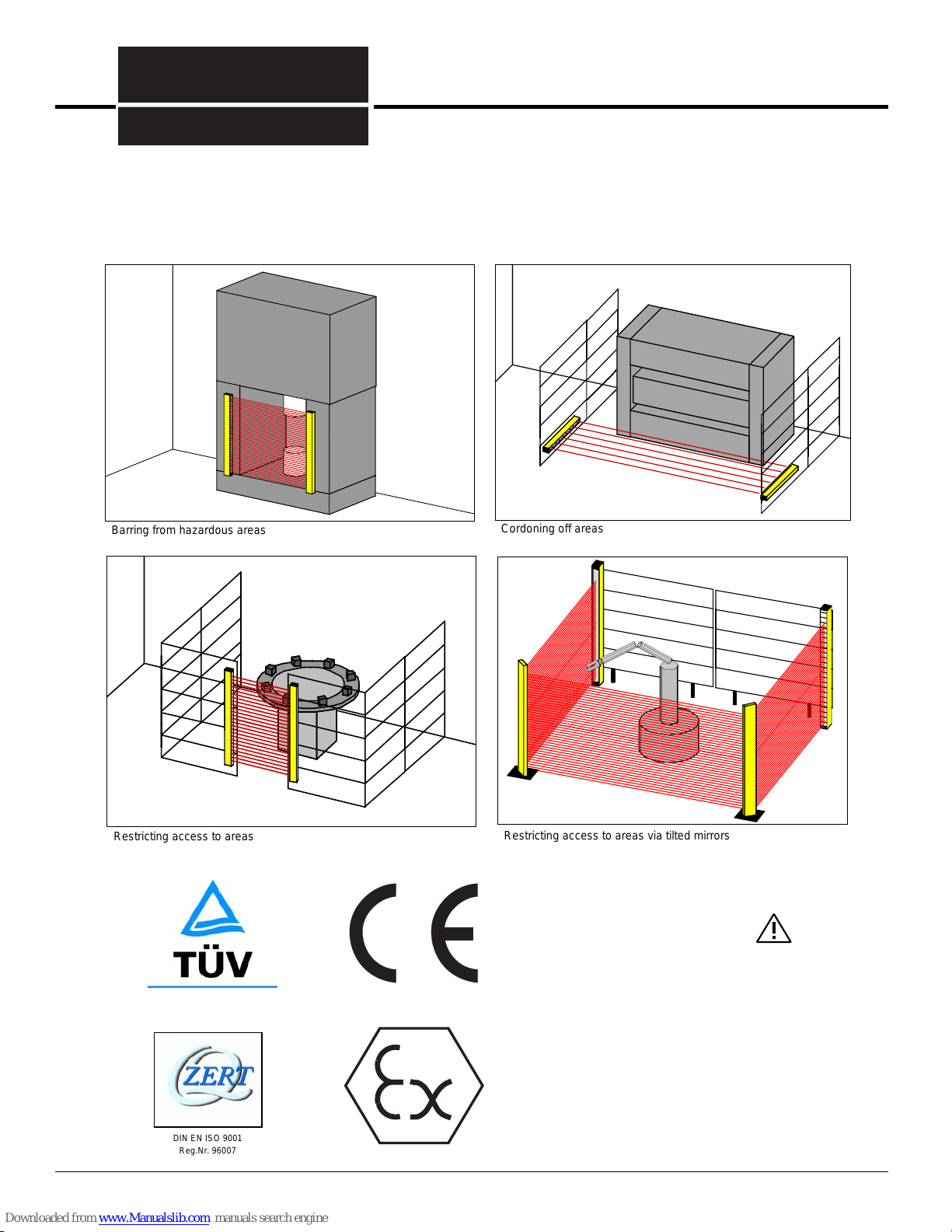
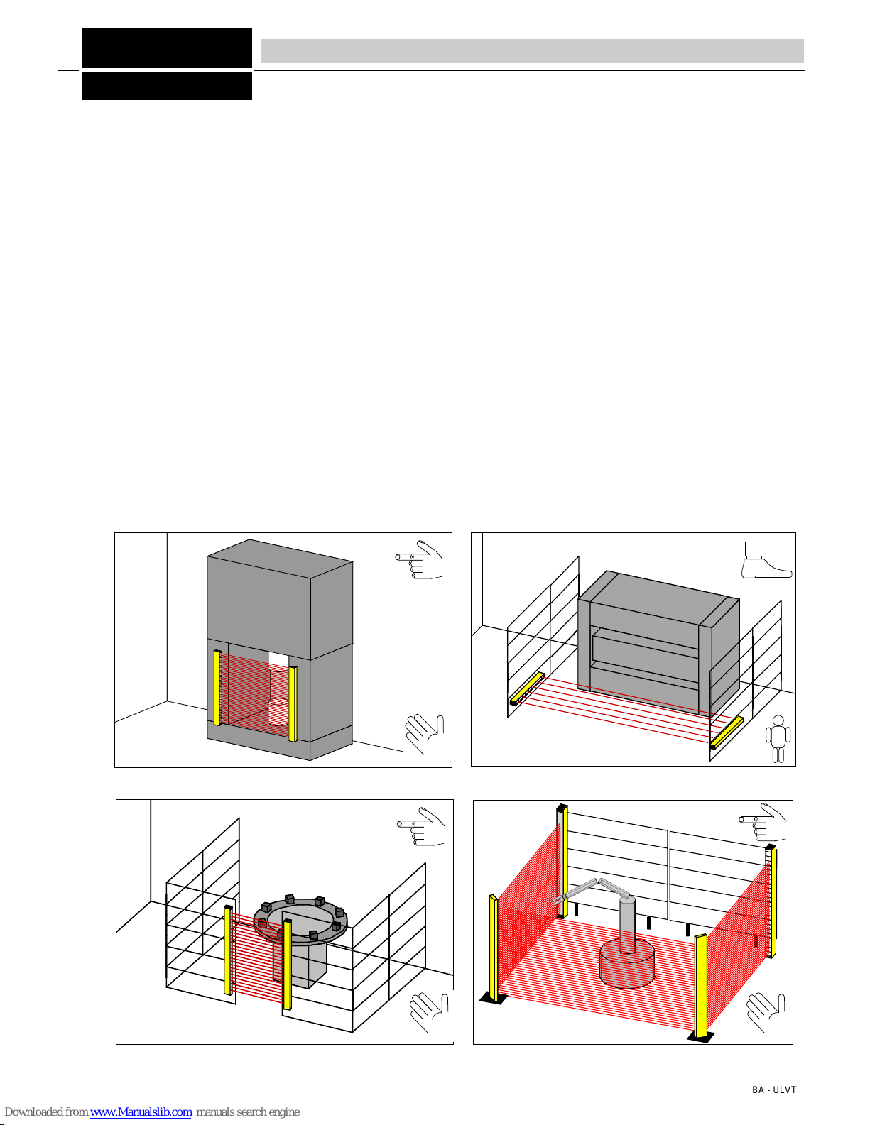
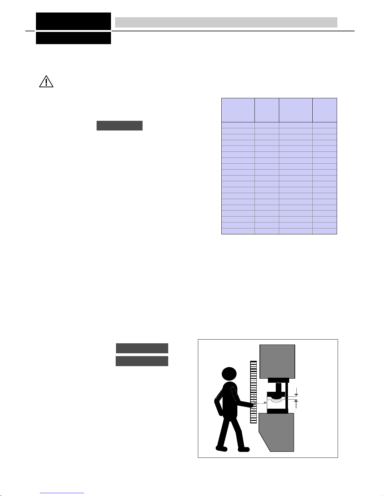
4.1 Safe distance from hazardous area
The safe distance (S) between the accident-preventing light barrier and hazardous area must be big enough to ensure that when
the protective field is penetrated, the hazardous area cannot be accessed before the hazardous movement has been
ended. In addition, it must be ensured that reaching over, under or around, or walking behind the protective field is
prevented by additional mechanical screening or further light barriers. To this end, please also refer to EN 999 and
other effective national and international safety regulations.
4.1.1 Vertical light barrier protection of hazardous areas
The safe distance S is calculated as follows:
- K = Grabbing speed or approach speed
For the grabbing speed K, a speed of 2000 mm/s is preset. If the calculation
for S produces a value greater than 500 mm, the calculation can be repeated
with 1600mm/s if this does not lead to a value lower than 500 mm (smin > 100
mm)
- T = t1 + t2 t1 = Response time of the safety device
t2 = Run-on time of the machine
With ULVT light barriers, the response time of the safety
device
t1 depends on the number of beams (refer to Table 10/1).
When using the ULVT with the optional safety
switchgears, the
response time of the switchgears is added to t1:
For LSUW N1 Muting switchgear: 20 ms
For LSUW NSR 3-1K switchgear: 25 ms
For ULSG switchgear: 6 ms
The run-on time of the machine t2 must be specified by the
machine manufacturer.
- C = 8 (d - 14 mm) d = Definition of the safety device
(minimum detectable obstacle size)
The definition capacity d ( = 14 mm or 30mm) is specified on the nameplate of the ULVT light barrier,
for d =14mm => C=0, for d= 30 0> C= 128mm
Calculation examples for the safe distance with vertical area protection using ULVT light barriers
≥
Example 1:
ULVT100/13 safety light barrier
Run-on time t2 of the machine from 75 ms
S = 2000 mm/s x (0.075s + 0.006s)
S = 162 mm
Example 2:
ULVT500/35 safety light barrier
ULSG safety switchgear
Run-on time t2 of the machine from 75 ms
S = 2000 mm/s x (0.075s + 0.007s + 0.006s) +8(30mm-14mm)
S = 304 mm
Table 10/1 Response time t1 of the ULVT light
barriers (standard form factors)
SNachlaufweg
der Maschine
4 Installation - Safe distances
S = (K x T) + C
Fig. 10/1 Vertical protection of hazardous areas
For S = 100 mm to 500 mm:
For S > 500 mm:
S = (2000 mm / s .T)
S = (1600 mm / s .T)
BA - ULVT
Run-on path
of the machine
Protective field
height / no of
smallest
obstacle
14mm
reaction
time
(ms)
14mm
Protective field
height / no of
smallest
obstacle
30mm
reaction
time
(ms)
30mm
ULVT100 /13 6 ULVT100 /7 5
ULVT200 / 26 7 ULVT200 / 14 6
ULVT300 / 39 8 ULVT300 / 21 6
ULVT400 / 52 9 ULVT400 / 28 7
ULVT500 / 65 10 ULVT500 / 35 7
ULVT600 / 78 11 ULVT600 / 42 8
ULVT700 / 91 12 ULVT700 / 47 9
ULVT800 / 104 13 ULVT800 / 56 9
ULVT900 / 117 14 ULVT900 / 63 10
ULVT1000 / 130 15 ULVT1000 / 70 10
ULVT1100 / 143 17 ULVT1100 / 77 11
ULVT1200 / 156 18 ULVT1200 /84 12
ULVT1300 / 169 19 ULVT1300 / 91 12
ULVT1400 / 182 20 ULVT1400 / 98 13
ULVT1500 / 195 21 ULVT1500 / 105 13
ULVT1600 / 208 22 ULVT1600 / 112 14
ULVT1700 / 221 23 ULVT1700 / 119 15
ULVT1800 / 234 24 ULVT1800 / 126 15
ULVT1900 / 247 25 ULVT1900 / 133 16

4.2 Horizontal protection of hazardous areas
FIESSLER
ELEKTRONIK
11
4 Installation - Safe distances
AAA
AAA
AAA
AAA
AAA
AAA
AAA
AAA
AAA
A
A
A
A
A
A
AA
AA
AA
AAAAAAAA
AAAAAAAA
AAAAAAAA
AAAAAAAA
AAAAAAA
AAAAAAA
AAAAAAA
AAAAAAAA
AAAAAAAA
AAAAAAAA
AAAAAAA
AAAAAAA
AAAA
AAAA
AAA
AAA
AA
AAA
AAA
AA
AA
AA
A
A
A
A
A
AAAAAAAA
AAAAAAAA
AAAAAAAA
AAAAAAA
AAAAAAA
AAAAAAA
AAA
AAA
AAA
AA
AA
AA
AA
AA
AA
AAA
AAA
AAA
AAA
AAA
AAA
Calculation examples for the safe distance with
horizontal protection of hazardous areas using
ULVT light barrier:
Example:
ULVT1200/156 light barrier
Response time t1 of light barrier: 18 ms
Run-on time t2 of machine: 50 ms
H = 200 mm
The safe distance is:
S = (1600 mm / s x (0.050 s + 0.018)) +
(1200 mm - 0.4 x 200 mm)
S = 1229 mm
With the ULVT 1200/156, the protective field
depth is 1200 mm.
A distance abetween protective field and
machine of 53 mm provides a safe distance
S= 1253 mm
Formula for calculating the safe
distance with horizontal protection of
hazardous areas using a light barrier:
Here:
K = 1600 mm/s
C = 1200mm-0.4H, but smaller than 850
mm, whereby H is the height in mm
of the protective field above the
reference level, e.g. floor.
With a height of the protective field above
the floor of > 300 mm, a risk of crawling
under exists. This must be considered in
risk assessment.
The following condition thus applies for H
≥300 mm:
1200 - 0.4 x H > 850 mm
The distance a of the end of the
protective field (last beam to front
edge of hazardous area) must be
no more than:
Example:
Height 200 mm
a = 200 / 15 + 40 mm
a = 53 mm
S = (1600 mm / s x T) + (1200 mm - 0,4 H)
a = H / 15 + 40 mm
S = Safe distance
Start of protective field (first beam) to
front edge of hazardous area
H
Front edge of hazardous area
H= Height of protective field to reference level
S = (K x T) + C
a = Distance from last beam of protective
field to front edge of hazardous area
S
a
BA - ULVT

4.2.1 Installation without additional screening
The light transmitter (a) (Fig. 12/1) and the light receiver (b)
form the light barrier (c). If the light beams are interrupted, e.g. by
a hand, a pilot circuit is opened and the closing action is
prevented / stopped. In the opposite example, it is not possible
to avoid the ULVT light barrier from the working side, which
means that additional screening is not required.
In order to prevent the walking behind the protective field,
the distance between the ULVT safety light barrier and the
machine must be _< 75 mm.
4.2.2 Protection against reaching under and over
In a normal working process (Fig. 12/2a), the operator inserts the
workpiece when sitting down. Due to the run-on time of the machine, the ULVT safety light barrier (a) is mounted slightly in
front of the hazardous area (refer to Section 4.1). However, the light barrier height selected here leaves an unprotected
gap at the top of the light barrier. Fig. 12/2b shows how reaching over the light barrier can lead to an accident. The
proper rectification of this problem is illustrated in Fig. 12/2c, where a ULVT safety light barrier with a larger
protective field height has been attached.
FIESSLER
ELEKTRONIK
12
4 Installation - Construction requirements
Fig. 12/1 Installation without additional screening
Fig. 12/2a.b.c Protection against reaching under or over.
12/2.a 12/2.b 12/2.c
If the distance between the vertical ULVT safety
light barrier and the machine needs to be
greater than 75 mm (e.g. in order to maintain
the safe distance to the hazardous area), the
possibility of walking behind the protective field must be
eliminated through an additional ULVT safety light barrier
and/or cascading of two light barriers (Fig. 12/3 and 12/4) or a
protective bar.
Fig. 12/3 Protection against walking behind through cascading of two light
barriers
In cascading, varying form factors can becombined (e.g. main
sensor with 1100 mm protective field height and succeeding
sensor with 200 mm protective field).
When combining main and succeeding sensors, the max. beam
number of 247 must be ob-
served
The main and succeeding
sensors are supplied with
premanufactured
connecting
cable.
AAA
AAA
AAA
AAA
AAA
AAA
AAA
AAA
AAA
AAA
AAA
AAA
AAA
AAA
AAA
AAA
AAA
AAA
AAA
AAA
AAA
AAA
AAA
AAA
AAA
AAA
AAA
AAA
AAA
AAA
AAA
interdictionde
redŽmarrage
ULVT
Empfänger
7654321
1.24V±20%
2.0V
3.PE
4.A1
5.A2
6.Schützhilfsöffner
7.Start-Taster
ULVTReceiver/Récepteur
Wiederanlauf
Justierhilfe
LS
LSfrei
restartinterlock
adjustment
LCinterrupt
LCfree
Aided«ˆjustement
libre
interrompu
BWSTyp4, ESPEType4 , ESPS Type4
FIESSLER
EL E K T R O N I K
unterbrochen
sperre
AAAAAAAAAAAAAAAA
AAAAAAAAAAAAAAAA
AAAAAAAAAAAAAAAA
AAAAAAAAAAAAAAAA
AAAAAAAAAAAAAAAA
AAAAAAAAAAAAAAAA
Fig. 1274 Cascading of two safety light
barriers
BA - ULVT
Wrong! Right!
4.2.3 Protection against walking behind through cascading or additional screening
Wrong! Right!

4.2.4 Distance from reflective surfaces
To prevent the avoidance and non-
detection of an obstacle due to
reflecting objects, the
ULVT safety light barrier
must be assembled with
a minimum distance a
(Fig. 13/1) from the
reflective object.
The minimum distance acan be
established from the table:
4.2.5 Arrangement of two ULVT... safety light barriers
To eliminate the mutual clashing of
two ULVT... safety light barriers, the
following must be observed when
arranging two light barriers:
FIESSLER
ELEKTRONIK
13
Installation range in m Up to 3 4567
Distance a in mm 130 175 219 262 306
Empfänger
SenderEmpfänger
AAAAAAAA
A
AAAAAA
A
AAAAAAAA
SenderEmpfänger
Sender Empfänger
SenderEmpfänger Sender
Empfänger Sender
4 Installation - Construction requirements
Fig. 13/1 Distance from reflective surfaces
Fig. 13/2 Arrangement of 2 light barriers
AAAAAAAAAAAAAAAAAAAAA
A
AAAAAAAAAAAAAAAAAAA
A
AAAAAAAAAAAAAAAAAAAAA
max. 5o
AAAAA
AAAAA
amax. 5o
Hazardous area
Reflective object
(e.g. container)
ULVT receiver ULVT transmitter
Approach direction
Interrupted beam Central beam
Container
BA - ULVT
Receiver Transmitter
Transmitter Receiver
Receiver Transmitter

4.3 Installation of transmitter and receiver
When installing the transmitter and receiver, it must be ensured that connectors of both devices are located on the same side.
The receiver and transmitter must be installed with parallel faces.
Attachment and adjustment The supplied fastening brackets serve the attachment and adjustment of the light
barrier. Together with the shifting tenon blocks, the latches enable a universal
attachment.
The swivel the longitudinal axis, turn the respective adjusting screw on one of the
fastening brackets whilst both screws on the other fastening bracket are loose. To swivel
the lateral axis, turn both screws of a fastening bracket at the same time whilst both
screws on the other fastening bracket are loose.
Rubber-metal connection
In the event of intense vibrations, please use rubber-metal connections which can be obtained as optional accessories.
Wall mounting example
FIESSLER
ELEKTRONIK
djusting screws with counter nuts for swivelling along longitudinal and lateral axes.
Further adjustment information is provided in Section 6, "Commissioning".
Bore dia.: 7 mm for attachment of
light barrier
4 Installation - Installation of transmitter and receiver
M6 x 15 DIN 912
50 x20 x 2
A
A
A
A
A
A
A
A
40 X 90 x 6
40 X 90 x 6
50 x20 x 2
M8 DIN 912
M8 DIN 127
M6 DIN 934
M6 DIN 127
A
A
A
A
A
A
A
A
A
A
A
A
A
A
A
Longitudinal
axis
Lateral axis
Fig. 14/1 Installation with parallel faces
Fig. 14/2 Swivelling along longitudinal and
lateral axis
Depends on run-
on time of machine
Machine
Important: In order to ensure error-free operation, both the light transmitter and light receiver
must attached to stable, distortion-free and face-parallel constructions. Install the
fastening brackets so that the adjusting screws remain easily accessible.
Make sure that the shape is not distorted. Otherwise a perfect visual adjustment will
not be possible. Adjust one fastening bracket whilst the adjusting screws on the other
fastening bracket are loose.
BA - ULVT 14

4.4 Multi-sided screening through tilted mirrors
Using tilted mirrors, the protective field can be "wrapped around" a hazardous area, thus providing protection from several
sides (Fig. 15/1 and Fig. 15/2). Here, the law of reflection applies, whereby the angle of incidence is the same as the angle of
reflection. This means for that tilting of 90°requires the mirror to be installed at an angle of 45°. For this purpose, the tilted
mirrors for ULVT feature swivelling attachments.
Reflection loss: Each reflection via a mirror weakens the transmitted signal. For this reason, the max. range and number of
mirror reflections must be observed when using mirrors. The transmitter, receiver and mirrors must always be assembled
vertically and checked using a spirit level.
Operational reliability can only be ensured when the mirrors are assembled in a stable manner.
Refer to Section 6 for precise adjusting information.
4.5 Assembly columns
For installation in an open area (e.g. for the multi-sided protection of hazardous areas), the ULVT light barriers and titled
mirrors can supplied as premanufactured assembly columns.
FIESSLER
ELEKTRONIK
15
4 Installation - Operation via tilted mirrors
Column for ULVT and mirrors
Elongated assembly slot for M12
Top cover (mirror)
Front and top lid
(transmitter, receiver)
4 adjusting screws for assembly column
BA - ULVT
Base plate as drilling template for M12 base attachment and for
supporting the adjusting screws
Fig. 15/1 Arrangement of 2 tilted mirrors Fig. 15/2 Arrangement of 1 tilted mirror
Mirror Mirror Receiver
Receiver
Mirror
Transmitter Transmitter
Hazardous area Hazardous area
Fig. 15/3 Assembly columns for light barrier and mirrors

Installation of the columns
1. Provide electric connection of transmitter and
receiver
2. Optically align the transmitter, receiver and mirrors
3. Check for correct function
4. Drill the holes and attach the columns
The transmitter, receiver and mirror columns are
attached horizontally at the same height. A precise spirit
level must be used to check this. With vertical
arrangement, the 4 adjusting screws are used on the
respective posts. The columns can be rotated using the
elongated assembly slots. In addition, the mirror can be
rotated by loosening the M8 hexagon nut on the
connecting rod located below the top cover. The
supplied black base plate assists the fitter in drilling the
M12 holes in the floor for the columns. It must be
ensured that the columns are aligned as shown in the
opposite drawing.
Fine tuning is carried out as described in Section 6,
"Commissioning". The front and top covers must be
removed for this purpose. The front cover must be
reattached once assembly and adjustment has been
completed.
FIESSLER
ELEKTRONIK
16
AAAAAAAAAAAAAAAAAAAAAA
A
AA
AA
A
AA
A
A
A
A
A
AA
AA
AAA
AAA
A
A
A
A
A
A
A
AA
AA
AAAA
AAAA
AAAA
AAAA
AAAA
AAAA
A
A
A
A
AAAAA
AAAAA
AA
AA
AA
AA
AA
AA
AA
A
A
AAAAAA
AAAAAA
AAAAAA
AAAAAA
AAAAAA
AAAAAA
AAAAAA
AAAAAA
AAAAAA
AA
AA
A
A
A
AA
AA
AA
A
A
A
A
A
A
A
A
AA
AA
AA
AA
A
A
A
A
A
A
A
AAAAAAA
AAAAAAA
AAAAAAA
AAAAAAA
A
A
A
A
AAAAA
AAAAA
AA
AA
AA
AA
AA
AA
A
AAAAAAAAAA
AAAAAAAAAA
AAAAAAAAAA
AAAAAAAAAA
AAAAAAAAAA
AAAAAAAAAA
AA
AA
A
A
AAAAAAAAA
AAAAAAAAA
AAAAAAAAA
AAAAAAAAA
AAAAAAAAA
AAAAAAAAA
AAAAAAAAA
AAAAAAAAA
AAAAAAAAAAAAAAAAAAAAAA
AA
AA
AA
AA
AA
A
A
A
A
A
A
A
A
AA
AA
AA
AA
A
A
A
A
AA
AA
A
AAAAAAA
AAAAAAA
AAAAAAA
AAAAAAA
AAAAAAA
A
A
A
A
A
A
AA
AA
AA
AA
AA
AAAAA
AAAAA
A
A
AA
AAAAAAAAAA
AAAAAAAAAA
AAAAAAAAAA
AAAAAAAAAA
AAAAAAAAAA
AAAAAAAAAA
AA
AA
AA
AA
A
A
AA
AA
A
A
A
AA
A
A
A
A
A
AAA
AAA
A
A
A
AA
A
AA
A
AAAA
AAAA
AAAA
AAAA
AAAA
AAAA
AAAA
A
A
A
A
AA
AA
AA
AA
AA
AAAAA
AAAAA
AA
AA
AA
AAAAA
AAAAA
AAAAA
AAAAA
AAAAA
AAAAA
AAAAA
AAAAA
AAAAA
AAAAA
AA
AA
AA
AA
AAAAAAAAA
AAAAAAAAA
AAAAAAAAA
AAAAAAAAA
AAAAAAAAA
AAAAAAAAA
AAAAAAAAA
AAAAAAAAA
AAAAAAAAA
90o
4 Installation - Assembly columns
Fig. 16/3 Installation of the columns
140
1250
10
AAAAAAA
AAAAAAA
AAAA
A
AA
A
A
AA
A
A
AA
A
A
AA
A
A
AA
A
A
AA
A
A
AA
A
A
AA
A
A
AA
A
A
AA
A
A
AA
A
A
AA
A
A
AA
A
A
AA
A
A
AA
A
A
AA
A
A
AA
A
A
AA
A
A
AA
A
A
AA
A
A
AA
A
A
AA
A
A
AA
A
A
AA
A
A
AA
A
A
AA
A
A
AA
A
AAAA
110
AAAA
AAAA
AAAA
AAAA
AAAA
AAAA
AAAA
R7
M8
27
30
200
200
140
1250
10
AAAAAAA
AAAAA
A
AAA
A
A
AAA
A
A
AAA
A
A
AAA
A
A
AAA
A
A
AAA
A
A
AAA
A
A
AAA
A
A
AAA
A
A
AAA
A
A
AAA
A
A
AAA
A
A
AAA
A
A
AAA
A
A
AAA
A
A
AAA
A
A
AAA
A
A
AAA
A
A
AAA
A
A
AAA
A
A
AAA
A
A
AAA
A
A
AAA
A
A
AAA
A
A
AAA
A
A
AAA
A
A
AAA
A
AAAAA
110
200
AAAA
AAAA
AAAA
AAAA
AAAA
AAAA
AAAA
AAAA
DIN 970-M8
DIN 970-M8
Fig. 16/1 Assembly column with ULVT light barrier Fig. 16/2 Assembly column with mirrors
BA - ULVT

5.1 Integrated connector plug
The ULVT construction series is supplied with
PG threaded joints as standard. Various
conventional connector plugs can also be
obtained as optional accessories.
The electric connection is implemented via
terminal screws in the connector cover (Fig.
17/1). The cover can be removed once the 4
screws have been loosened.
The transmitter and receiver require a power supply of 24 V DC. The ULSG switchgear performs the power failure bridging of
20 ms pursuant to EN 60204 and is thus suitable as the power supply for ULVT light barriers. The receiver is equipped with 2
inputs and 2 outputs. The transmitter is connected via one 3-pin cable and the receiver via one 5 to 7-pin cable (depending on
operating mode). The permissible cable cross-section is max. 1.5 mm2. The cables must be routed separately from power
lines.
5.2 Electric connection ratings
5.3 Connectors
- Outputs 1 and 2 (OSSD 1 and OSSD 2)
The outputs are not potential-free and must not be switched in series
or parallel, but must be connected and processed separately!
In the operating mode with
equivalent outputs
, both PNP outputs are
failsafe and feature internal short-circuit and cross-circuit monitoring. Both
outputs are high (+24 V) when the light path is free.
In the operating mode with
antivalent outputs
, output 1 is high (+24 V)
and output 2 low (0 V) when the light path is free. Output 2 is not failsafe
in this operating mode. This operating mode is only permissible in
conjunction with the safety switchgears LSUW NSR 3-1K, LSUW N1-
Muting K, or another safe sequential phase control device which
monitors output 2!
- Input contactor check (EDM)
If the operating mode with
contactor check
is set, the auxiliary contacts
k1 and k2 of the driven contactors k1 and k2 must be connected to the
contactor check input in series and with +24 V as shown in Fig. 17/2.
The OSSD1 and OSSD 2 of the ULVT will only switch on the two
contactors when contactor check input has detected the idle status of the
contactors (+24 V at contactor check input).
Once the contactors have been driven, both of them must respond within
300 ms. The two auxiliary contacts must then be open (0 V at contactor
check input).
If the operating mode
without
contactor check
is set, the input
contactor check must be unoccupied.
FIESSLER
ELEKTRONIK
17
5 Electric connection - Connection of receiver and transmitter
The electric connection must only
be carried out when no voltage is
present.
ULVTS transmitter ULVTE receiver
Power supply 24 V DC, + 20% - 10%, SELV 24 V DC, ±20%, SELV
Current draw max. 250 mA max. 250 mA (without load)
Outputs -
OSSD 1 and 2
: Failsafe PNP outputs,
max. 0.5 A, short-circuit and cross-circuit monitoring (in
operating mode with
antivalent outputs
, output 2 is a non
-
failsafe PNP output, max 20 mA)
Inputs -Inputs contactor check and start button:
0 V to 24 V DC _+ 20%, 10 mA
Electric connection Integrated connector plug with PG9 as strain relief,
alternatively conventional connector plug. Integrated connector plug with PG9 as strain relief,
alternatively conventional connector plug.
Connecting cable 3-pin max. 1.5 mm2 5 to 7-pin (depending on operating mode) max. 1.5 mm2
Protection category IP 65 IP 65
AAAAA
AAAAA
AAAAA
AAAAA
AAAAA
AAAAA
AAAAA
AAAAA
OSSD 2
OSSD 1
3
4
7+24V DC±20%
0V
6K 1 K 2
Fig. 17/2 Outputs 1 and 2
AAAAAA
AAAAAA
AAAAAA
AAAAAA
AAAAAA
AAAAAA
AAAAAA
AAAAAA
AAAAAA
0V
7
2
+24V DC±20%
Eingang Schützkontrolle
6
Hilfsöffner k1
Hilfsöffner k2
Fig. 17/3 Input contactor check
123 4 56 7
3: OSSD1 5:
2: EDM 7: 24VDC
±20%
4: OSSD2
1: Start
123456
off
1234567 123
6: 0V
Fig. 17/1 Integrated connector plug with terminal screws in
connector cover
Receiver 7-pin, transmitter 3-pin.
BA - ULVT
auxiliary contact 1
auxiliary contact 2
input contactor check

- Input start button
If the operating mode with
restart interlock
is set, a button must be
connected on the start button input for the start release of the operating
movement (Fig. 18/1).
With a free protective field, the yellow LED on the receiver lights up as a
start prompt. Only once the start button has been pressed will the two
outputs OSSD1 and 2 of the ULVTE receiver be switched to active.
If the operating mode
without restart interlock
is set, the start button
input (start) must be unoccupied).
5.4 Connection examples
5.4.1 Operating mode with restart interlock / contactor check
5.4.2 Operating mode without restart interlock / contactor check
5.4.3 PLC drive
When connecting to a safe stored program control (PLC) the outputs of the ULVT must be connected to
seperate inputs of the PLC
FIESSLER
ELEKTRONIK
18
5 Electric connection - Connection of receiver and transmitter
Caution! Error-free operation can only be ensured when the safety light barrier is connected according to one of the following
connection diagrams (and/or as shown in Section 7), and also complies with effective national and international
accident prevention regulations!
Any deviation from these connection specifications can lead to hazardous conditions and is therefore not permitted.
7654321
+24V DC±20%
0V
OSSD 2
OSSD 1
Schützkontrolle
Start-Taster
K2
K1 k1 k2
1234567
Erde
123
+24V DC+20%-10%
0V
Erde
7654321
123
+24V DC±20%
0V
OSSD 2
OSSD 1 K2
K1
+24V DC+20%-10%
0V
1234567
Erde
Erde
unbelegt
unbelegt
7654321
123
+24V DC±20%
0V
OSSD 2 E1
OSSD 1 E2
+24V DC+20%-10%
0V
1234567
Erde
Erde
unbelegt
unbelegt
Sicherheits-
SPS
AAAAAA
AAAAAA
AAAAAA
AAAAAA
AAAAAA
AAAAAA
AAAAAA
AAAAAA
0V
7
1
+24V DC±20%
Start-Taster
6
Eingang Start-Taster
Fig. 18/1 Start button input
Receiver
Transmitter
Receiver
Transmitter
Receiver
Transmitter
Note:
The functional ground
(marked GND in the
opposite connection
examples) must be
connected at the
transmitter and
receiver in order to
ensure EMC
resistance.
BA - ULVT
Contactor check
Start button
GND
GND
Start button
Input start button
GND
GND
GND
GND
Unoccupied
Unoccupied
Unoccupied
Unoccupied
Safety
PLC

6.1 Commissioning
Prior to commissioning, the appropriate operating mode for the respective application case must be set via the DIP switches in
the terminal strip compartment (refer to Section 3.5). When delivered, the operating mode with restart interlock, contactor
check and equivalent outputs is set (refer to Section 5).
6.1 Adjustment information
The visual alignment is advantageously carried out with intensely dimmed ambient lighting in order to be able to better detect
the LED indications of the receiver even from a long range.
When aligning, it must be ensured that the housing shapes do not become distorted.
An adjustment laser can be obtained for the precise alignment of the ULVT light barriers,
particularly where large distances are involved. The device is attached to the front panel of
the transmitter and receiver. When the button is pressed, the laser lights up red light spot
which can also be seen from long distances. The light spot must hit the centre of the
opposite device. This test should be performed at both ends of the transmitter and receiver.
The arrangement must be adjusted if necessary.
Adjustment with operation via tilted mirrors: Place the adjustment laser onto the front
panel of the transmitter, switch it on and swivel the transmitter until the light spot hits the
centre of the mirror. Then adjust the mirror so that the light spot also hits the centre of the second mirror / receiver.
Adjustment LED: The orange LED extinguishes when sufficient light reserve is present.
Fine tuning
Subsequent to face-parallel installation and/or alignment using the adjustment laser, fine
tuning is carried out by means of the adjusting screws on the supplied fastening brackets,
provided that the orange LED is lit.
The swivel along the longitudinal axis, the respective adjusting screw on one of the fastening
brackets is turned whilst both screws on the other fastening bracket are loose. To swivel the
lateral axis, both screws of a fastening bracket are turned at the same time whilst both
screws on the other fastening bracket are loose.
Subsequently, the green or yellow LED on the receiver should light up, and the orange
LED must have extinguished.
Test rod: Using the test rod, the light barrier is to be interrupted on the transmitting side from start to finish in such a way that the
light field is only covered by this part. The green LED must not light up from start to finish. The diameter of the test rod must
correspond to the obstacle size specified on the nameplate of the receiving side.
FIESSLER
ELEKTRONIK
19
Light barrier free
and correctly
adjusted
Outputs active Outputs not active,
(Prompt for start release with start button)
Light barrier free,
but insufficient
reserve
Outputs active
To swivel along longitudinal or
lateral axis until orange LED
extinguishes
Outp
Outputs not active,
(Prompt for start release with start button)
To swivel along longitudinal or lateral axis
until orange LED extinguishes
6 Commissioning
Longitudina
l axis
Lateral axis
interdiction de
redŽmarrage
Wiederanlauf
Justierhilfe
LS
LS frei
restart interlock
adjustment
LC interrupt
LC free
Aide d«ˆjustement
libre
interrompu
unterbrochen
sperre interdiction de
redŽmarrage
Wiederanlauf
Justierhilfe
LS
LS frei
restart interlock
adjustment
LC interrupt
LC free
Aide d«ˆjustement
libre
interrompu
unterbrochen
sperre
interdiction de
redŽmarrage
Wiederanlauf
Justierhilfe
LS
LS frei
restart interlock
adjustment
LC interrupt
LC free
Aide d«ˆjustement
libre
interrompu
unterbrochen
sperre interdiction de
redŽmarrage
Wiederanlauf
Justierhilfe
LS
LS frei
restart interlock
adjustment
LC interrupt
LC free
Aide d«ajustement
libre
interrompu
unterbrochen
sperre
Operating mode Without restart interlock With restart interlock
BA - ULVT

6.3 Troubleshooting
The prerequisite for the troubleshooting process is a correctly adjusted light barrier (refer to Section 6.2)
Please observe: Solvents can damage the plexiglass panels of the transmitter and receiver. As an alternative, light barriers
with silicate glass can be delivered. Welding spots can burn into the silicate glass panels. This is prevented by a
replaceable protective panel made out of PVC.
Maintenance information: The ULVT... system is maintenance-free depending on the construction. The protective panels in
front of the transmitter and receiver should simply be cleaned at regular intervals with a solvent-free detergent. This does not,
however, release the obligation to carry out the prescribed annual inspection pursuant to EN 61496, ZH 1/281 and/or ZH
1/597.
FIESSLER
ELEKTRONIK
20
Operating / fault status Possible causes Remedy
Yellow LED off No power supply Check power supply
Yellow LED flashing Internal error, transmitter inactive Switch off power supply and then
switch on again. If yellow LED still
flashes: Transmitter defective, replace
transmitter
6 Commissioning - Troubleshooting
Transmitter
Operating / fault status Possible causes Remedy
No LED illuminated No power supply Check power supply
Green LED off
Red LED on
Orange LED on
Yellow LED off
a) Transmitter inactive
b) Light path interrupted
c) Light barrier maladjusted or very dirt
d) Max. range exceeded
a) Check transmitter
b) Remove obstacle from light path
c) Readjust and/or clean system
d) Check range
Green LED off
Red LED on
Orange LED off
Yellow LED on
(no fault)
Operating mode with restart interlock
active, prompt for start release
Press start button
Green LED off
Red LED off
Orange LED on
Yellow LED off
a) Insufficient reserve, light barrier
maladjusted or slightly dirty
b) Max. range exceeded a) Readjust
and/or clean system
a) Readjust and/or clean system
b) Check range
Green LED and/or
Orange LED flashing a) In operating mode with contactor
check: Contactors not responding or fal-
len
b) Operating mode setting does not
match the electric wiring and/or DIP
switches are not set as specified in
Sect. 3.5.
c) Internal error
a) Check auxiliary contact k1 and k2
and/or wiring
b) Check operating mode setting
c) Switch off power supply and then
switch on again
If LED still flashes: Check operating
mode setting; if correct mode set -
receiver defective, replace receiver.
Receiver
interdiction de
redŽmarrage
Wiederanlauf
Justierhilfe
LS
LS frei
restart interlock
adjustment
LC interrupt
LC free
Aide d«ˆjustement
libre
interrompu
unterbrochen
sperre
Sender ein Transmitter on
Emetteur en
marche
interdiction de
redŽmarrage
Wiederanlauf
Justierhilfe
LS
LS frei
restart interlock
adjustment
LC interrupt
LC free
Aide d«ˆjustement
libre
interrompu
unterbrochen
sperre
interdiction de
redŽmarrage
Wiederanlauf
Justierhilfe
LS
LS frei
restart interlock
adjustment
LC interrupt
LC free
Aide d«ˆjustement
libre
interrompu
unterbrochen
sperre
interdiction de
redŽmarrage
Wiederanlauf
Justierhilfe
LS
LS frei
restart interlock
adjustment
LC interrupt
LC free
Aide d«ˆjustement
libre
interrompu
unterbrochen
sperre
Sender ein Transmitter on
Emetteur en
marche
BA - ULVT
Table of contents