manuals.online logo
Brands
  1. Home
  2. •
  3. Brands
  4. •
  5. EZ
  6. •
  7. Garden House
  8. •
  9. EZ 8' Gambrel User manual

EZ 8' Gambrel User manual

STEP 1. GENERAL
STEP 2. INVENTORY
STEP 3. FRAME PREPARATION
E-Z BUILD BARN GUIDE
8' ×8' • 8' ×12' • 8' ×16'
You can
construct
your own
E-Z frame
barn with
the help of
this step by
step guide.
Prior to beginning construction, the area
selected for the shed location must be level
and cleared of obstructions.
North American
softwood
dimensional
lumber sizes:
Nominal Actual
in × in
1 × 4 ¾× 3½
1 × 6 ¾× 5½
2 × 4 1½× 3½
2 × 6 1½× 5½
PLEASE NOTE: This shed construction aid is intended solely to provide general knowledge as to one of the ways
a shed may be constructed. We suggest you check with your local building ofcials regarding site location, permit
procedures, safety regulations and specications of materials used to construct your new storage shed. Builders
who utilize this aid must proceed at their own risk and are solely responsible for complying with all building codes
which pertain in their community. Midwest Manufacturing hereby disclaims all liability for any damages whether
consequential, incidental, special or otherwise, which may result from following this do-it yourself aid.
Separate all lumber, hardware, etc. into
individual stacks of like items.
Unfold each frame, setting aside two frames
to be used as end walls. From 1×4 pine
boards, cut gusset plates 6" long:
• 16 for an 8' building • 24 for a 12' building
• 32 for a 16' building. Apply gusset plates
on each side of top and bottom fold
locations. Use four 8d nails on each gusset
plate. Frames used as end walls require only
one gusset plate at the top and bottom on the side opposite the metal plates. See gure 1.
Figure 1
2×4 Roof Frame
Members
2×4 Sidewall
Frame Member
Treated 2×4 Bottom
Frame Member
1×4×6" gusset
plate at top fold
location
1×4×6" gusset
plate at bottom
fold location
7513⁄16"
601⁄8"
39"
8'0"
1½"
45"
821⁄16"
96"
BUILD
STEP 4. BACK WALL FRAME STEP 5. FRONT WALL FRAME
STEP 6. SIDING BACK WALL STEP 7. SIDING FRONT WALL
Using one frame selected as an end wall, measure and mark stud locations according to dimensions
shown in gure 2. Place the proper length 2×4 studs at those locations. Mark required length and
angles. Cut each 2×4 to t. Toe nail studs into place using (2) 8d nails top and bottom. See gure 2.
Using the remaining end wall frame, repeat step 4, using gure 3 as a guide.
Place two 4'×8' sheets of wall sheathing face
down side-by-side on a level surface. Place the
back wall frame on the sheathing, as shown in
gure 4. Trace the back wall frame onto the
sheathing, remove frame and cut along the lines.
Properly place sheathing on the frame and nail
into place using 6d nails every 8" on center.
Using the front wall frame, repeat step 6, using
gure 5 as a guide. Prior to cutting lines for the
doors, extend outlines out 1" in all directions.
Cut “new” lines for your doors shown in STEP 8.
Properly place siding on frame and nail using 6d
nails every 8" on center.
NOTE: Some siding pieces will need to be butted together, so a straight cut is necessary. To keep
moisture from “wicking” into the siding, keep the bottom of the siding 1" above the bottom of the
treated bottom frame member.
Figure 2 Figure 3
Figure 4 Figure 5
2×4 door header cut to t
Toe nail into place.
Install this piece FIRST.
2×4 door uprights
Measure and cut to t.
48"
48"
50"
48"
48"
48"
1" 1"
Trace
frame.
Cut
lines. Cut “new” lines out 1"
from traced lines of top
and sides for doors.
Siding
shown
face
down.
Siding shown
face down.
3½"
22¼" 20½" 20½" 22¼"
2"×4"×8'0"
end wall studs
cut to t.
Toe nail studs into
place (Typ).
3½"
20½" 48"
79"
2×4 center nailer
cut to t
Use scrap pieces to
cover tails.
Use scrap pieces to
cover at peak.
STEP 8. DOOR FRAMING
STEP 10. SQUARE THE BUILDING
STEP 11. FLOOR SUPPORTS
STEP 9. RAISING FRAMES
Cut 1×4 boards and attach to the door siding
interior with siding extending 1" out top & sides.
Extend 1×4 board out 1" for the center of one
door. Ensure bottom boards clear treated end
frame joist. Bend protruding 8d nails. Cut and
fasten 2×4 cross braces. Cut 1×4 boards and
attach ush to door siding exterior. Apply hinges
and hasp. See gure 6. Attach 1×4 trim to the
front wall sided frame and fasten doors to the
frame.
At base of building, measure diagonally. Adjust building
until AD=BC. Building is then square. See gure 8.
From the remaining treated 2×4’s cut (4)
21¼" oor supports and the required amount
of 22½" oor supports:
• 4 for an 8' building
• 8 for a 12' building
•12 for a 16' building
Install as shown in gure 9, using 10d nails.
From treated 2×4’s, cut rim joists:
• 95" for an 8' building
• 191" for a 16' building
• 143" for a 12' building
Place the rim joists 8' apart in the
area where the shed is to be set.
Stand the front and back walls up
at the proper ends of the rim joists.
Temporarily brace both ends. Nail
rim joists to the end walls using 10d
nails. See gure 7.
Stand the remaining frames up:
• 3 for 8' building
• 5 for 12' building
• 7 for 16' building
Place a temporary brace across the
roof frame members. Nail frames to
rim joists at dimensions shown.
Figure 6
Figure 8
Figure 9
Figure 7
2×4
Brace
Treated end frame Joist
Temporary braces
Standard
Frames
1"
22¾"
22¾"
22½"
1½"
22½"1½" 1½"
Nail in place
2×4 treated
oor supports.
(typical)
1×4×6" gusset
plates at top
and bottom fold
locations
(typical)
21¼"
8'0"
End wall
21¼"22½"
22½"
1" Gap, Top & Sides
1×4
Pine
Boards
Hinge
locations
Outside
edge of frame
to outside edge of
frame - not siding
12"
12"
82½"
Front end wall shown
with optional T1-11 siding
A
C
B
D
43½"
43½" 42"
42"
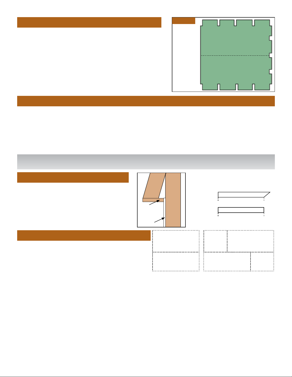
STEP 12. FLOOR SHEATHING
STEP 15. ROOF
STEP 13. SIDING WALLS
• 8' Building: Cut (2) 4'×8' sheets of ¾" oor sheathing
to 95" long. Notch each piece to t wall frame members.
Nail in place using 8d nails every 8" on center.
• 12' Building: From one 4'×8' sheet of ¾" ooring,
cut 2 pieces 47½" long. Cut (2) 4'×8' sheets to 95½"
long. Notch each piece as required to t wall frame
members. Fasten with 8d nails every 8" on center.
• 16' Building: Cut (4) 4'×8'×¾" sheets to 95½" long.
Notch as required to t wall frame members.
• 8' Building: The total overall length of your roof
from the outside of back wall sheathing to outside
of front wall sheathing should be 96". From a sheet
of 4'×8' OSB sheathing cut and install 96"×40" for
the bottom roof slope. Nail in place with 6d nails every 8" on center. For the top roof slope cut a
4'×8' sheet of OSB sheathing to 45" wide. Nail in place and repeat for the opposite side.
• 12' Building: For the bottom slope cut pieces 96"×40"and 48"×40" from two sheets of 4'×8' OSB
sheathing. Nail in place with 6d nails every 8” on center. For the top slope cut pieces 96"×45" and
48"×45". Nail in place and repeat for the opposite side.
• 16' Building: For the bottom slopes cut four sheets of 4'×8' OSB sheathing to 96"×40". Nail in
place with 6d nails every 8" on center. For the top slope cut four sheets to 96"×45". Nail in place.
• 8' Building: Cut (4) 4×8 sheets of sheathing to 47½"×46" long. Apply sheathing in vertical
direction. All splicing is done on centers of frame, and save cut-os to use in gable ends.
• 12' Building: Cut (6) 4'×8' sheets of sheathing: 4 @ 47½"×46" & 2 @ 48"×46".
Apply sheathing in vertical direction.
• 16' Building: Cut (8) 4'×8' sheets of sheathing: 4 @ 47½"×46" & 4 @ 48"×46".
Apply sheathing in vertical direction.
Figure 10
Notch for
Uprights
Seam
NOTE: If T-1-11 siding is used place cut edges at corners and all splicing is done on centers of frames.
Make certain end walls and frames are plumb (vertically level), then fasten using 6d nails.
Apply roof edge and felt. Apply shingles as per instructions printed on bundles.
96"×45" 96"×45"
48"×45"
96"×40" 96"×40" 48"×40"
For the Sot use:
• 8' Bldg: 1×6×8' boards
•12' Bldg: 1×6×12' boards
•16' Bldg: 1×6×8' boards
Nail to the exposed ends of the roof
frame members using 8d nails.
STEP 14. SOFFIT & TRIM
Siding
1x6
Sot
Board
4 Pieces
4 Pieces
1×4
1×4
Cut to t.
Cut to t.
Corner
trim on
end walls
Corner
trim on
sidewalls
COPYRIGHT BY Midwest Manufacturing 2016 www.midwestmanufacturing.com

This manual suits for next models

1

Popular Garden House manuals by other brands

Yardmaster 66 ZGEY Assembly instructions

Yardmaster

Yardmaster 66 ZGEY Assembly instructions

Mercia Garden Products 0628LOG181-V4 manual

Mercia Garden Products

Mercia Garden Products 0628LOG181-V4 manual

Lemeks Palmako PA120-5930-6 Assembly, installation and maintenance manual

Lemeks

Lemeks Palmako PA120-5930-6 Assembly, installation and maintenance manual

Rion Hobby Gardener Assembly instructions

Rion

Rion Hobby Gardener Assembly instructions

Select ISAAC E9682 Assembly manual

Select

Select ISAAC E9682 Assembly manual

Palmako Saale installation manual

Palmako

Palmako Saale installation manual

Palmako Roger FR44-5953-2 installation manual

Palmako

Palmako Roger FR44-5953-2 installation manual

Lemeks Palmako Grace PM56-4529 Assembly, installation and maintenance manual

Lemeks

Lemeks Palmako Grace PM56-4529 Assembly, installation and maintenance manual

Mercia Garden Products 03WES0808-V1 General instructions

Mercia Garden Products

Mercia Garden Products 03WES0808-V1 General instructions

Mercia Garden Products 03DTSHHP1206HGD4MW-V1 General instructions

Mercia Garden Products

Mercia Garden Products 03DTSHHP1206HGD4MW-V1 General instructions

Shire Salcey Assembly

Shire

Shire Salcey Assembly

Pergola kits USA PREMIUM VINYL PAVILION Assembly manual

Pergola kits USA

Pergola kits USA PREMIUM VINYL PAVILION Assembly manual

G21 Boston 882 manual

G21

G21 Boston 882 manual

Mercia Garden Products 05DTMBPN0503DD-V1 Assembly instructions

Mercia Garden Products

Mercia Garden Products 05DTMBPN0503DD-V1 Assembly instructions

Rutland County Burley 6ft Assembly instructions

Rutland County

Rutland County Burley 6ft Assembly instructions

Palmako Roger 27,7 installation manual

Palmako

Palmako Roger 27,7 installation manual

Mercia Garden Products 01PTOSBA0306DDNW-V1 General instructions

Mercia Garden Products

Mercia Garden Products 01PTOSBA0306DDNW-V1 General instructions

Gartenhaus-King Valery manual

Gartenhaus-King

Gartenhaus-King Valery manual

manuals.online logo
manuals.online logoBrands
  • About & Mission
  • Contact us
  • Privacy Policy
  • Terms and Conditions

Copyright 2025 Manuals.Online. All Rights Reserved.