manuals.online logo
Brands
  1. Home
  2. •
  3. Brands
  4. •
  5. Shire
  6. •
  7. Garden House
  8. •
  9. Shire Salcey User manual

Shire Salcey User manual

A 18/01/2011 J Shepherd
1. Check all components before
commencing with the construction
of your Salcey
2. The only parts that may require
trimming are the final roof and
floorboards.
3. Keep all timber dry or your building
will not fit together.
4. We also recommend that you seal
the corner log joints with silicone
sealant (not supplied).
5. We recommend a minimum of two
people required for assembly.
6. Read through all the instructions
before constructing your pine lodge.
7. You will see there is a set of lettered
drawings showing each side of the
building. You will find these letters
printed at one end of each log or in
the slot.
Adult assembly only-Do not attempt to modify this playhouse
Thank you and congratulations on the purchase of your Shire pine lodge.
We believe that this product will give you many years of excellent service.
This is a natural product manufactured to a high standard therefore if you
have any queries or experience any difficulties then please contact our
customer service hotline on 01945 46 89 10 01945 46 89 11 01945 46 89 12
Normal office hours: 8.30am to 5.00pm Monday to Friday. Answer phone all other times.
Assembly of Salcey play cabin
See drawings for log quantities
QTY DESCRIPTION Sizes in mm
Floor
5 Pressure treated floor bearers 38x63x1600
11 Floor Boards 139x14x1540
3 Skirting 25x40x1600
1 Skirting 25x40x900
1 Skirting 25x40x250
Terrace
5 Pressure treated deck bearers 38x63x395
4 Deck boards 22x95x1590
2 Terrace capping pieces V1 20x70x330
2 Terrace end caps V2 20x7x600
Roof
3 Roof joists 44x44x2090
1 Felt 10m roll
4 Fascia-2 plain –2 wavy
32 Roof Boards 139x14x1060
2 Diamond
2 Angled eaves edging 2090
2 Roof edging 44x44x2090
Doors & Windows
1 Door
1 Door frame
1 Black door ring
1 wooden door knob
1 Continuous door hinge
1 Roller door catch set
QTY DESCRIPTION
1 CE mark plaque
2 Window frames
2 Window inserts
4 Window hinges
2 Casement stays
4 Casement stay pins
12 Styrene glazing
48 Beading
Other &Hardware
2 Vent kits
28 80mm screws
100 50mm screws
1 45mm flat head screw (for wooden knob)
60 25mm screws
205 40mm round , flat head nails
170 40mm oval nails
110 Felt nails
100 Panel pins
2 playhouse window boxes
Preparation of base
Prior to assembly a suitable perfectly level concrete base must be
provided. Actual floor area 2790 mm x 2090 mm.
Parts list
Treatment/care of your pine lodge
All timber must be dry to apply the timber treatment.
Treat with a suitable decorative wood finish immediately. We recommend
that
you treat the door and window slots (fig 22 & 23) with a top quality timber
treatment before assembly and treat the entire building as soon as
assembly is complete, we further recommend that all pieces are treated
and again within 3months of assembly and again at least annually or as
frequently as the instructions on the product used recommends.
We would also remind you that you would rarely (if ever) be able to
re-treat the underside of the floor boards following assembly. We strongly
recommend that the underside of the floor is treated an absolute minimum
of twice, the floor bearers are pressure treated and don’t need to be
treated although you may if you wish. Use only child safe wood
preservative and allow to dry thoroughly before further use. Do not
use creosote.
Tools required
●Hammer
●Rubber mallet
●Spirit level
●Stepladder
●Battery-powered drill/screwdriver
●8mm drill
●3mm drill
●Tape measure
●Gloves
IMPORTANT!
Completed Salcey play cabin
Wood is a natural product and is therefore
prone to changes in appearance, including
some warping, movement and splitting,
particularly during unusual climatic conditions
(long hot or wet spells of weather). As a natural
occurrence this is not covered by a guarantee.
PLEASE NOTE
PLEASE LAY OUT PARTS AND CHECK OFF AGAINST CHECK LIST BELOW:
B 18/01/2011 J Shepherd
• We recommend the wearing of non-
slip protective gloves throughout
the assembly process. We also
recommend the wearing of steel
capped protective shoes,
protective head gear, safety glasses
and full length clothing. If step
ladders are to be used we recom-
mend one person holds the ladder
whilst the other is using them. If
necessary a third person should be
used. Do not attempt to erect the
building in windy conditions. Follow
any safety precautions quoted by
the manufacturer for any equipment
you use.
• Every precaution has been taken to
ensure that your building has no
element incorrectly placed or
possibly hazardous. However prior
to use please check for raised grain
or splinters and sand if necessary.
Check that all elements are secure
against reasonable force.
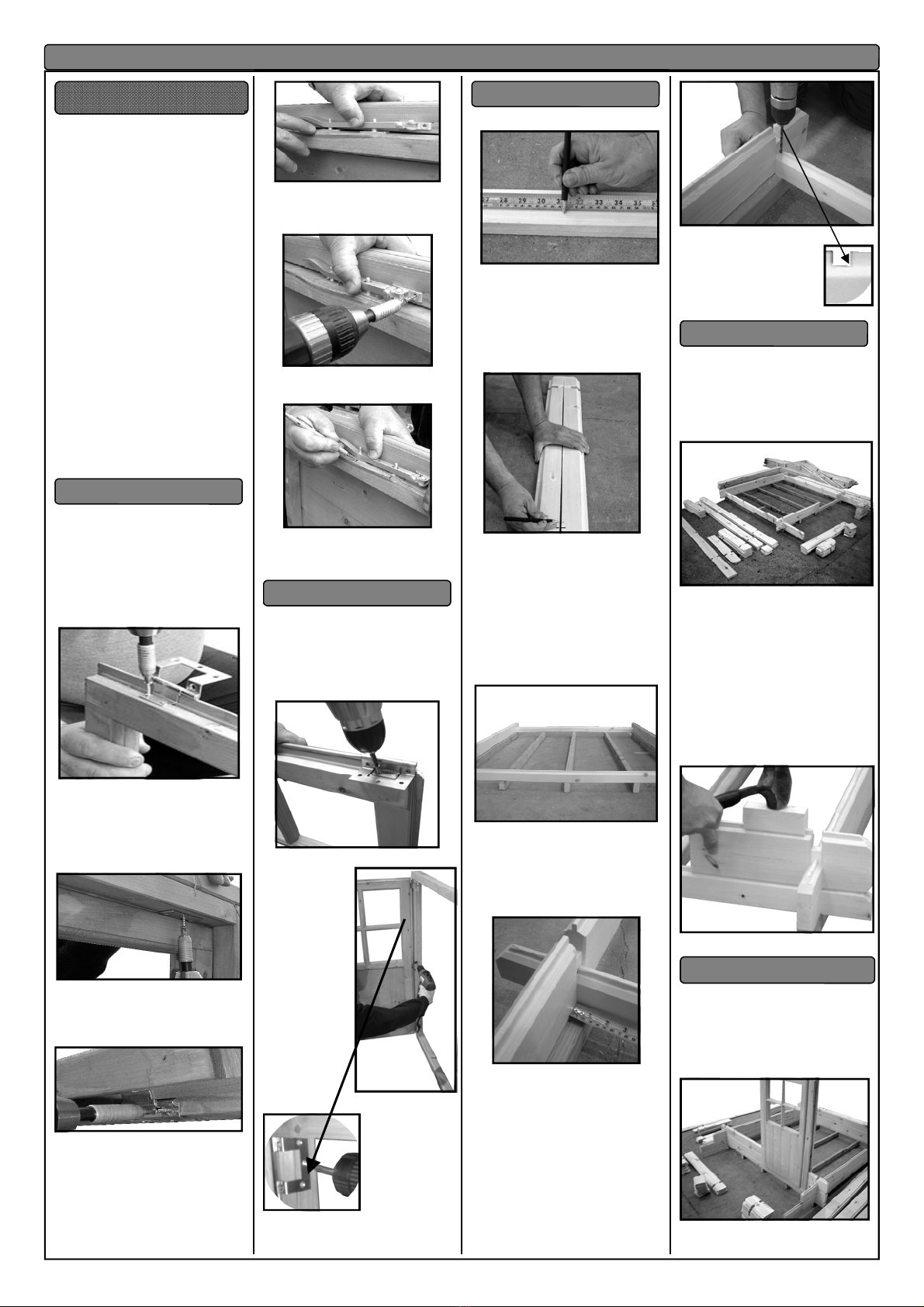
1. Place one hinge on the inner rebate
part of the window; approx. 50mm along
from the rebate edge. The rounded part
of the hinge should sit above the outer
edge of the window. Screw the inner
piece into position ( fig. 1 )using the pre
drilled holes in the hinge and 2x 25mm
screws. Repeat.
Fig 1
2. Place the window into the aperture.
Secure the window to the panel using
3x 25mm screws per hinge, (fig. 2 )
again through the predrilled holes I n the
hinge. Repeat.
Fig 2
3 From the outside, open the window
fully in order to fit a further 2x 25mm
screws per hinge ( Fig.3 ).
Fig3
4 Fitting the Casement Stay. Place
the casement stay centrally on the
inside of the window (Fig 4 ). Place the 2
pins under the casement stay.
Position so that it is not resting on the
window frame and not so high that the
pins are of no use.
Fig 4
5 Fit the Casement Stay (fig 5 ) on the
window using 2x 25mm screws.
Fig 5
6 Mark where the ‘pins’ will be placed.
Fig 6
7 Secure into position using 4x 25mm
screws - 2 in each pin
.1. Place the continuous hinge along the
length of the door (fig 7 ) making sure
that the hinge does not protrude at either
top or bottom.
2 .Fit the small inner part of the hinge to
the door using 6 x25 mm screws in total
fig 7
3 Fitting the door
to frame. Place
the door into the
aperture. Ensure
there is an equal
gap between the
edges of the door
and the aperture.
Screw into position
using 3 x 25mm
screws per hinge.
(fig 8 & 9)
Fig 8
Fig 9
See drawing pages1& 2 .
Fig 10
1. Take one of the A1 logs and mark the
895mm from one end (fig 10 ) . This is
the centre line of the middle bearer,
2. Mark 388mm either way of this line.
(This is the centre of the next two
bearers).
Fig 11
3. Place the other ’A1’ log against the
first one and transfer the lines across
(fig 11).
4. Layout pressure treated base floor
bearer timbers (See page 1 of the
drawing sheets.)
5. The bearers stand with the narrowest
edge to the floor (fig 12 ) and their ends
flush with the outside of the A1 logs.
Fig 12
6. Position the bearers that sit under the
full logs at the sides and measure 20mm
from the log to the edge of the bearer
( fig 13 ), all the way down . This is for
the floorboards to sit on.
Fig 13
8. cut notches out of the tongues on the
A1 logs ( fig 14)at centre marks (steps 1
to 3 above ) and drill through for fixing
bearers
9. Important
Measure corner to corner, as building
must be square
10 Also measure length at the centre of
the building from wall to wall (A1 toA1) to
ensure correct length
before fixing to joists with 1x 80mm
screw (fig14) at each bearer at each end.
Fig 14
See drawing pages 2,3,4,5,6,7
1 Using parts list for each wall layout
correct quantity (fig 15 ) of each
component
for relevant wall (i.e. front, back) in
suitable position for ease of assembly.
Fig 15
2. This is the bottom of all four walls
now ready to be built upon.
3. The walls can now be assembled
as per pages 2,3,4,5 and 6.start
building walls either anti-clockwise
or clock-wise direction.
4. The logs are assembled with the
tongues upwards
9 Each log needs to be tapped home
to log below using timber block
supplied and a rubber mallet (fig 16).
Fig 16
1 Door unit must be placed into
position after the first two layers of
full logs have been assembled
2 Slide unit into aperture from above
(Fig 17& 18) ensuring unit is
completely down and in position.
Fig 18
IMPORTANT SAFETY INFORMATION
A Hinges-windows
B Fit door
C Base frame
D Walls
E Inserting windows and doors
Assembly of playhouse –please read instructions prior to assembly
C 18/01/2011 J Shepherd
fig19
3 Window units are fitted as above
fig 20) when you have built up to the
correct height
Fig 20
4 Note Door and window units do not
require fixing
5. Slide all pieces between door and
window into place from above.
6 Once the door and window units are
in place continue assembling the walls
as before but slide the logs into the door
or window frame (fig 21) from above
then tap them down.
Fig 21
1 Once gables are in place knock down
all the walls again as in fig 16 to ensure
all the walls are fully home
2 Fix the gable with1x80mm screw at
each end (fig 22.)
Fig 22
1 Fit roof bearers into slots provided in
the gable sections (fig 23 & 24).
Fig 23
2 Measure the distance between each
roof bearer and the roof bearers and
walls to ensure all components are fully
home before continuing.
Fig 24
3 Position the eaves edging strips
( fig 25 &26) level at both ends with the
gable angle (front and back walls) and
screw to the wall with 50mm screws at
approximately 400 centres.
Fig 25
Fig 26
4 The first roof board is now ready to
be positioned (fig 27).
Fig 27
5 Start at the front, place the board level
with the end of the roof bearers and
central over the middle bearer to pro-
duce an even overhang (fig 27).
6 Fix into place at the roof bearers and
angled eaves edgings using two 40mm
nails at each bearer & eaves edging
Fig 28
7 The final roof board will need to be
cut. Place it in position and measure the
distance between the end of the roof
bearers and the edge of the board. This
will tell you how much you need to cut off
(fig28).
8 Next fit the roof edgings to the sides of
the building with 50 mm screws at
approximately 300mm centres (Fig. 29).
Fig 29
1 see drawing pages 1& 2
2 space out the floor bearers (319mm
between ) with the widest side to the
floor.
3. place the first deck board on top of the
boards ( fig 30 )and ensuring that it is
flush and true with the bearers screw at
each bearer with 2 x 50mm screws.
Fig 30
4 To prevent finger entrapment use a £1
coin as a spacer (less than 5mm) (fig
31 ) fix the rest of the deck boards as
before.
Fig 31
5. slide into position .
1 One 10m -roll of felt has been
supplied,
Fig 32
2 measure the length of the roof (fig 32)
and add 100 mm to that length . This
length is used to cut 3 strips from the
roll. (fig 33)
.
Fig 33
3 use a piece of floorboard as a guide to
cut the felt. (fig 34)
Fig 34
4 measure up 966mm and mark (fig 35)
at the front and back of each side of
( and along ) the roof.
Fig 35
5 Starting at the lower edge (eaves)
place 1 piece of felt from front to back of
the building
6 An overhang of approximately 100mm
should be allowed at the front and the
back (all felt strips) and the length of the
eaves edgings at the side (Fig 36).
7 line up the felt at the marks (step 4)
leaving enough for a 50mm overhang
( fig 36)then Secure with felt nails at
approximately 100mm spacing. But only
a couple along the high edge at this time
(nailed with overlap).
Fig 36
.8 Repeat on the other side.
9. Place the last piece across the ridge.
(high point ) Evenly overlap the other
pieces of felt (fig 37 ) . then nail as
before.
Fig 37
Fig 38
10. 8 On the underside of the outside
corners (fig 38 ) neatly cut, fold and
secure using 1x felt nail.
11. Nail with felt nails at each roof
bearer leaving space for fixing the
fascias.
F Gables
G Roof assembly
H Verandah floor
I Felt roof
D 18/01/2011 J Shepherd
1 Fascia boards can now be drilled
and screwed ( fig 39 ) with 1x50mm
screw at each roof bearer and the roof
edgings. Wavy at the front plain at the
back
Fig 39
2 Drill diamond and screw with 2x50mm
screws .(fig 40)
Fig 40
1 The floor is fitted working from front
to back with 40mm nails
2 Position the first floorboard under
the doorframe (Fig 41), with the
groove against the wall.
Fig 41
3 Fix into position with two nails at each
floor bearer (Fig 42& 43)
fig 42
Fig 43
4 Continue with remaining floorboards
until you have three remaining.
5 Place these in position without nailing
them down, as the last floorboard will require
trimming.
6 Measure the distance between the last full
board and the wall (Fig 44). This measure-
ment is then marked on the final board and
then cut to Fit , leaving the groove on the
board
Fig 44
7. curl the boards up ( fig 45 ) to put it into
position and nail the remaining boards before
.
Fig 45
1 Place ring handle on the outside of the
door. Place the handle approx. half way
up the door (fig 46 ) making sure you are
central to the framework running across
the other side.
Fig 46
2 Mark the holes. Join the holes with a
marker (fig 47). Then drill at the top
corner point but far enough in to clear
the screws. (6mm Drill Bit).
fig 47
3 .Place the wooden handle on the
inside of the door and screw from the
outside; using the hole just drilled
( fig 48 ) and 1x 45mm flat head screw.
Fig 48
4 Fix the ring handle, using 4x 25mm
black screws on the other side of the
door covering the screw for the wooden
knob.
5 Door catch
Fig 49
6 place the spring piece of the catch
level with the inside edge of the door and
fix with the screws provided ( fig 49 ).
Fig 50
7 With the door closed push the catch
together. and mark the required position
of the door catch housing. Secure using
2 x screws provided (fig 50 ).
fig 51
1 Push vents into holes provided (fig
51).
2 Fix CE plaque above front door.
3 screw narrow logs K (fig 51 ) into
position .
Fig 52
3 Fix the logs K.( fig 52 ) and fix the
terrace capping pieces V1 with 2 x
50mm screws each.( fig 53 )
Fig 53
4 Fix the V2 posts to the deck bearer
(fig 54) with 1 x 80mm screw and then to
the each log with 80mm screws
Fig 54
4 Trim off the corners of the capping
pieces (fig 55)
Fig 55
1 Place the clear plastic glazing material
into the aperture of each window.
2 Hold into position with four pieces of
beading . The beading may need to be
swapped around to get the best fit. When
satisfied secure into position using 2x
15mm panel pins per piece of beading.
( FIG 56 )Repeat for all window and door
apertures.
Fig 56
3. Do not replace with glass.
J Fascia
K Floor
L Door furniture
M Finishing touches
N Glazing
1Check and ensure that no raised grain or splinters are
evident on timber components. Sand down any raised
grain or splinters using fine grade sandpaper.
2Check that all screw, nail and pin heads are properly
tapped home and are not proud of the timber surface.
3Check and ensure that no screws, nails or pins protrude
through any panel.
4 Check and ensure that all parts are properly secured
against reasonable force.
5Do not apply decorative wood finish/treatments to wet or
damp timber. Please observe the instructions of the wood
finish/treatment manufacturer. 6
6Adults need to check the playhouse regularly and main-
tain the playhouse in good condition to provide a safe
play environment. Do not use if damaged. If damaged the
playhouse should be properly and safely repaired before
further use by children.
. Assembly Completion Checklist

Other Shire Garden House manuals

Shire Casita 2016 User manual

Shire

Shire Casita 2016 User manual

Shire Garden Store User manual

Shire

Shire Garden Store User manual

Shire Jailhouse User manual

Shire

Shire Jailhouse User manual

Shire 6x4 Bar User manual

Shire

Shire 6x4 Bar User manual

Shire Guernsey 7x10 User manual

Shire

Shire Guernsey 7x10 User manual

Shire Rose Arbour User manual

Shire

Shire Rose Arbour User manual

Shire Lodge Playhouse User manual

Shire

Shire Lodge Playhouse User manual

Shire Paradise Bar User manual

Shire

Shire Paradise Bar User manual

Shire 46034 User manual

Shire

Shire 46034 User manual

Shire GSHE0706DSL-1AA User manual

Shire

Shire GSHE0706DSL-1AA User manual

Shire Arbour Foxglove User manual

Shire

Shire Arbour Foxglove User manual

Shire Larkspur User manual

Shire

Shire Larkspur User manual

Shire Den User manual

Shire

Shire Den User manual

Shire 8x8 Sun Pent Manual

Shire

Shire 8x8 Sun Pent Manual

Shire Workman 10x16 User manual

Shire

Shire Workman 10x16 User manual

Shire Abri Apex User manual

Shire

Shire Abri Apex User manual

Shire Aster 2020 User manual

Shire

Shire Aster 2020 User manual

Shire 10x10 Sun Pent Manual

Shire

Shire 10x10 Sun Pent Manual

Shire Bison Workshop User manual

Shire

Shire Bison Workshop User manual

Shire Flat Pack Loft User manual

Shire

Shire Flat Pack Loft User manual

Shire Crib Playhouse User manual

Shire

Shire Crib Playhouse User manual

Shire Elveden User manual

Shire

Shire Elveden User manual

Shire 10x6 Sun Pent Manual

Shire

Shire 10x6 Sun Pent Manual

Shire 7x5 Haddon 2022 User manual

Shire

Shire 7x5 Haddon 2022 User manual

Popular Garden House manuals by other brands

Lemeks Palmako 109452 Assembly, installation and maintenance manual

Lemeks

Lemeks Palmako 109452 Assembly, installation and maintenance manual

Karibu MERSEBURG 5 Assembly instructions

Karibu

Karibu MERSEBURG 5 Assembly instructions

Décor et Jardin MASSIF 28 T2 Assembly Notice

Décor et Jardin

Décor et Jardin MASSIF 28 T2 Assembly Notice

Palmako FRX70-5341 installation manual

Palmako

Palmako FRX70-5341 installation manual

Mercia Garden Products 01OSBA0707DDSW-V1 General instructions

Mercia Garden Products

Mercia Garden Products 01OSBA0707DDSW-V1 General instructions

WoodLife Garden 38589 Assembly instructions

WoodLife Garden

WoodLife Garden 38589 Assembly instructions

Palmako PM56-4435 installation manual

Palmako

Palmako PM56-4435 installation manual

Mercia Garden Products 01OSBRA0604SDFW-V1 General instructions

Mercia Garden Products

Mercia Garden Products 01OSBRA0604SDFW-V1 General instructions

Universo Consumer Products CK3421 Assembly instructions

Universo Consumer Products

Universo Consumer Products CK3421 Assembly instructions

Feider Machines FAJ200A Instructions for assembly

Feider Machines

Feider Machines FAJ200A Instructions for assembly

Palmako PAJ28-3030-1 installation manual

Palmako

Palmako PAJ28-3030-1 installation manual

Palmako Veronica PA34-3434-1 installation manual

Palmako

Palmako Veronica PA34-3434-1 installation manual

Palmako FR44-4735 installation manual

Palmako

Palmako FR44-4735 installation manual

Mercia Garden Products 03DTSHCV1208HGD4MW-V1 General instructions

Mercia Garden Products

Mercia Garden Products 03DTSHCV1208HGD4MW-V1 General instructions

Décor et Jardin 53212S043 Assembly Notice

Décor et Jardin

Décor et Jardin 53212S043 Assembly Notice

Forest CORNER SHED quick start guide

Forest

Forest CORNER SHED quick start guide

Luoman Lillevilla 577 Assembly and Maintenance

Luoman

Luoman Lillevilla 577 Assembly and Maintenance

Rowlinson SS008S Assembly instructions

Rowlinson

Rowlinson SS008S Assembly instructions

manuals.online logo
manuals.online logoBrands
  • About & Mission
  • Contact us
  • Privacy Policy
  • Terms and Conditions

Copyright 2025 Manuals.Online. All Rights Reserved.