Fairlight Prodigy 2 User manual

1
Installation Manual
SoftwareVersion 16.2
Part Number: DPR2202-A
Document Number: 163
Manual by: Owen P Walker
Copyright © August 2000

2
IMPORTANT NOTICE
COPYRIGHT
The material in this document is copyright to Fairlight ESP Pty Ltd, and may not be quoted
or reproduced in any form without written permission from the company.
LIMITED WARRANTY POLICY
All the software and hardware provided with, or purchased especially for, Fairlight
products has been tested for functionality. Fairlight ESP Pty Ltd will make its best efforts to
correct reported defects for future releases subject to technical practicabilities. Fairlight ESP
will also replace any defective media on which software has been delivered provided that the
item to be replaced is returned to the dealer who supported the product within 90 days of
purchase.
Fairlight ESP Pty Ltd makes no warranty or representation either expressed or implied
with respect to the system's performance or fitness for a particular purpose.
In no event will Fairlight ESP Pty Ltd be liable for direct or indirect damages arising from
any defect in the product or its documentation. Further, Fairlight ESP Pty Ltd will not accept
any liability for any programs, sounds, audio recording or sequences stored in or used with
Fairlight products, including the cost of recovery of such data.
The warranties, remedies and disclaimers above are exclusive and take precedence over
all others, oral or written, express or implied, to the extent permitted by law in the
geographical area of the product's use. No employee of Fairlight ESP, agent, distributor or
employee of an agent or distributor is authorized to offer any variation from this policy.
Copyright 2000:
Fairlight ESP Pty Ltd,
Unit 2, 1 Skyline Place,
French's Forest, NSW 2086,
AUSTRALIA.
Telephone +61 2 8977 9999
Fax +61 2 8977 9900

3
TABLE OF CONTENTS
IMPORTANT NOTICE ......................................... 2
CERTIFICATES & COMPLIANCES ........................... 5
CC EMISSION CONTROL .................................. 5
SAFETY SYMBOLS ............................................ 6
MAINS PLUGS & MAINS POWER CORDS .............. 7
OBTAINING TECHNICAL SUPPORT ........................ 8
SECTION 1 - INTRODUCTION ............................. 9
1.1 Product Description .............................. 9
1.2 Manual Summary ................................. 9
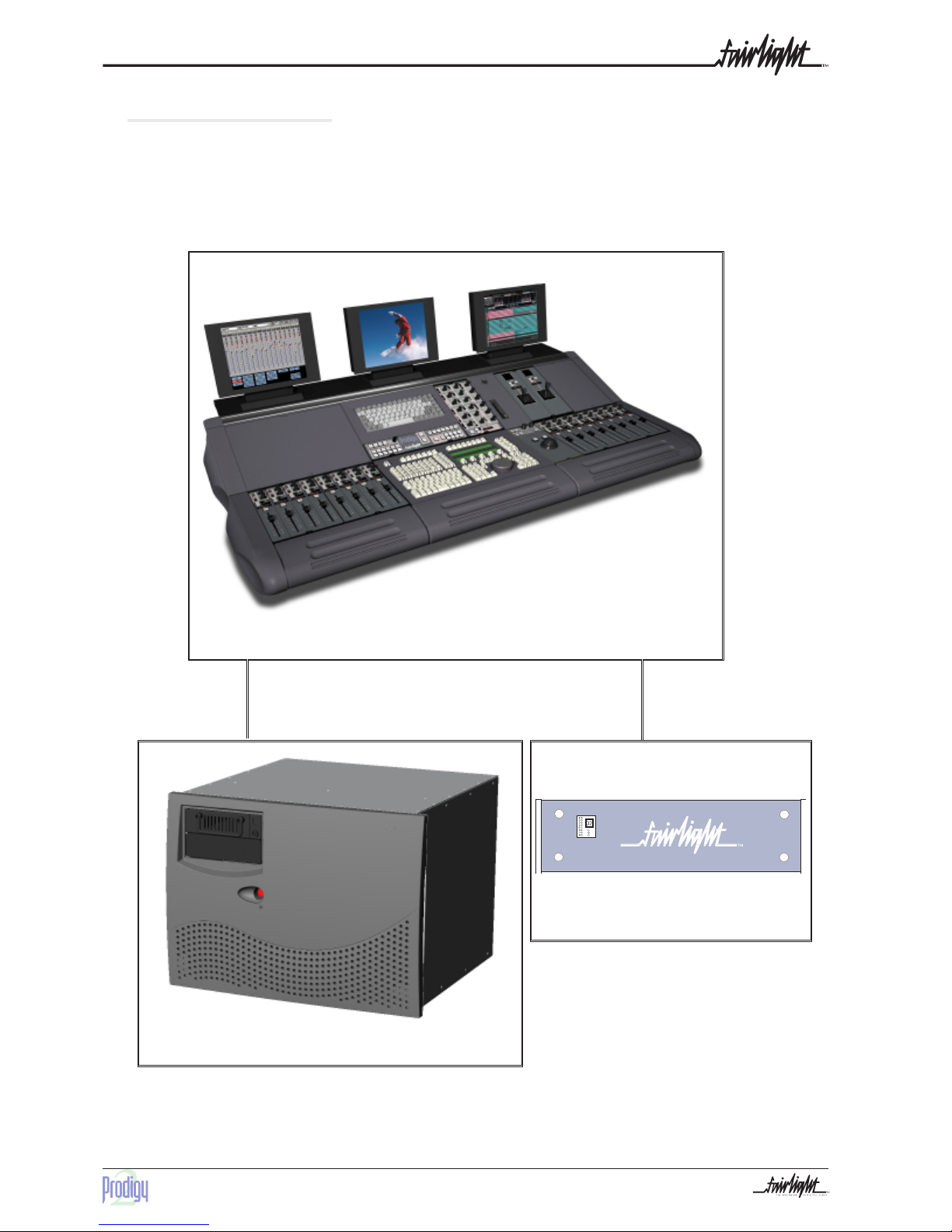
1.3 System Overview ............................... 10
1.4 Unpacking .......................................... 11
1.5 Equipment Supplied ............................ 11
1.6 System Overview ............................... 12
1.6.1 Prodigy 2 Engine ........................ 12
1.6.2 Prodigy 2 Control Surface .......... 12
1.6.3 Monitor Box ............................... 12
1.6.4 Audio I/O .................................... 12
1.7 Prodigy 2 Control Cable..........................
Interconnections ....................................... 13
1.8 Static Precautions ............................... 14
1.9 Environment........................................ 14
SECTION 2 - PHYSICAL INSTALLATION - ENGINE .... 15
2.1 Mechanical Installation ...................... 15
2.2 Electrical Installation .......................... 16
2.3 Engine Rear Panel Connections .......... 17
2.4 Cabling ............................................... 18
2.5 External Cable Length Considerations 18
2.5.1 SONY 9-PIN CABLE ....................... 18
2.5.2 VGA CABLE ............................... 18
2.5.3 AUDIO CABLE .............................. 18
2.5.4 DIGITAL AUDIO CABLES ................. 18
2.6 Connecting The Various Engine...............
Components .............................................. 19
SECTION 3 PHYSICAL INSTALLATION - CONTROL .......
SURFACE ..................................................... 20
3.1 Introduction......................................... 20
3.2 Mechanical Installation ...................... 20
3.3 Connecting The Various Prodigy 2 Surface
Components .............................................. 21
............................................................ 21
3.4 Surround Monitor and Remote Mic Amp
Setup. ........................................................ 22
3.5 Electrical Installation .......................... 23
3.5.1 Safety ......................................... 23
3.5.2 Mains input voltage .................... 23
3.5.3 Mains connection ....................... 23
3.5.4 Fuses ......................................... 24
3.6 Internal and External SCSI Devices.... 25
SECTION 4 - SYSTEM CONFIGURATION ............... 26
4.1 Introduction......................................... 26
4.2 Switching on the Equipment ............ 26
4.2.1 Engine .............................................. 26
4.2.2 Prodigy 2 Console ...................... 28
4.3 Prodigy 2 Engine Boot up.................... 29
4.4 Engine Software Installation ............... 31
4.7.1 Installing Software From Exabyte31
SECTION 5 - CONFIGURING DISK DRIVES .......... 32
5.1 External Hard Disk Drives ................. 32
5.1.1 Wide Based Disk Drives ............ 32
5.1.2 Narrow Based Disk Drives ........ 32
5.1.2 Configuring The Engine For Narrow
Use ...................................................... 33
5.1.3 Mixing Wide And Narrow Disk
Drives ................................................. 34
5.2 Checking for Newly Installed SCSI ........
Devices ................................................... 35
5.3 Setting Up Removable Media Devices35
SECTION 6 - BISCUIT PC CONFIGURATION ......... 36
6.2 BIOS Settings ...................................... 37
6.3 Software Installation for Prodigy 2 ..........
Surface..................................................... 38

4
B3.3 Main Inputs to Speaker Outputs ......
Specifications (Unity Gain) ................. 60
B3.4 Main & External Analogue Inputs
Specifications...................................... 60
B3.5 Analogue Outputs Specifications 60
B3.6 Monitor Box Connector View ........... 61
B3.7 EDAC Pinout Diagram ................ 62
B4 Monitor Box EDAC Connections.......... 63
C1 Prodigy 2 Surface Configuration.......... 65
C1.1 Surface VGA Cable .................... 65
C1.2 X-Link Cable .............................. 65
C1.3 Prodigy 2 Surface Mixer Cable ... 66
D1 Dimensions ......................................... 67
D1.1 - Prodigy 2 Engine, Surface and
Monitor Box......................................... 67
Prodigy 2 - Surface............................. 68
Prodigy 2 - Monitor Box ...................... 68
D1.2 Prodigy 2 Engine - Power .....................
Requirements ............................................ 69
SECTION 7 - ROUTINE MAINTENANCE ................ 39
7.1 Cleaning The Exterior Of The Units..... 39
7.2 Cleaning The Monitor Screens ............ 39
7.3 Cleaning The Engine Air Filter ............ 39
New Air Filters .................................... 40
APPENDIX - CONNECTION SPECIFICATIONS .......... 41
Introduction ............................................... 41
A1 - Audio I/O Configuration .................... 41
A1.1 Analog Audio I/O Specifications ...... 42
A1.2 Digital Audio I/O Specifications ....... 42
QDC Configuration ................................... 43
APPENDIX - CONNECTION & SIGNAL.....................
SPECIFICATIONS ............................................ 46
A2 Control & Reference Pinouts ............... 46
A3 General Purpose Interface .................. 47
A4 Mixer ................................................... 48
A5 Controller ............................................ 49
A6 Printer .................................................. 50
A7 9-Pin A ................................................. 51
A8 9-Pin B ................................................. 51
A9 9-Pin Slave .......................................... 52
A10 LTC - I/O ............................................ 52
A11 Serial Port .......................................... 53
A12 Midi I/O ............................................. 53
A13 AES Sync I/O ..................................... 54
A14 Modem .............................................. 54
A15 Engine VGA 1.................................... 55
A16 Video Sync - In .................................. 55
A17 Word Clock - In ................................. 55
A18 Word Clock - Out .............................. 55
B1 Example Monitor Box Connections For ...
5.1, LCRS and Stereo ................................ 56
B2 Surround Monitor Schematic ............... 57
B3 Monitor Box wiring .............................. 58
B3.1Standard Connections - Inputs ..... 58
B3.2 Standard Connections - Outputs . 59

5
CC EMISSION CONTROL
This equipment has been tested and found to comply with the limits for a Class A digital
device, pursuant to Part 15 of the FCC Rules. These limits are designed to provide reasonable
protection against harmful interference when the equipment is operated in a commercial
environment. This equipment generates, uses, and can radiate radio frequency energy and, if
not installed and used in accordance with the instruction manual, may cause harmful
interference to radio communications.
The Prodigy 2 Surface and Engine conform to the EMC directives :-
EN 55022:1998 Class A - Emissions
EN 55024:1998 Class 3 - Susceptibility
The Prodigy 2 Surface and Engine also conform to the Safety directives :-
UL 1419 - Professional Video & Audio Equipment
IEC 60950 - Information Technology Equipment
For further information on EMC procedures please refer to the following titles:-
Noise Reduction Techniques In Electronic Systems by Henry W Ott
EMC by Tim Williams
Operation of this equipment in a residential area is likely to cause harmful interference in
which case the user will be required to correct the interference at his own expense. Changes
or modifications not expressly approved by Fairlight ESP can affect emission compliance and
could void the user’s authority to operate this equipment.
CERTIFICATES & COMPLIANCES
CHARACTERISTICS DESCRIPTION
Equipment Type Supplemented Data: Information Technology
Equipment Class Supplemental Data: Class 1 - Grounded equipment
Installation Catergory Requirement Category 2 - Local level appliances,
portable equipment etc.
Pollution Degree
Requirement: Level 2 operating environment -
Normally only non-conductive pollution occurs.
Occasionally there may be a temporary conductivity
caused by condensation.

6
SAFETY SYMBOLS
The lightning flash with arrowhead symbol, within an equilateral
triangle, is intended to alert the user to the presence of un-insulated
“dangerous voltage” within the product’s enclosure; that may be of
sufficient magnitude to constitute a risk of electric shock to persons.
L’eclair, dans une triangle, est destiné à alerter l’utilisateur de la
présence de haute tension dangereuse non isolée dans l'enclosure du
produit, qui peut être d’un voltage suffisant pour constituer un risque
d’électrocution.
Das dreieckige Schild mit Blitzsymbol soll den Benutzer vor
unisolierten Hochspannungen innerhalb des Gerätes warnen. Es
besteht Lebensgefahr durch elektrischen Schlag!
El simbolo del rayo dentro de un triángulo equilátero, es usado
para indicar la presencia de un voltage peligroso en el interior del
aparato, de suficiente intensidad, como para constituir riesgo de
electrocución a las personas.
The exclamation point within an equilateral triangle is intended to
alert the user to the presence of important operating and maintenance
instructions in the literature accompanying the appliance.
Le point d’exclamation dans une triangle est destiné à alerter
l’utilisateur de la présence d’instructions importantes de
fonctionnement et d’entretien dans la littérature accompagnant
l’appareil.
Das dreieckige Schild mit Ausrufungszeichen soll den Benutzer auf
wichtige Bedienungs- und Wartungshinweise in der
Bedienungsanleitung hinweisen.
El simbolo de exclamación dentro de un triángulo equilátero avisa
al usuario de la presencia de instrucciones importantes acerca del
funcionamiento y mantención del aparato en los documentos que se
incluyen.

7
MAINS PLUGS & MAINS POWER CORDS
The following lists the recommended Mains Plugs and Leads for use in various countries
throughout the world.
Standards applicable for Mains Plugs Rating Country
ASTA BS1363 1984 10A @ 250VAC UK
BS546, 1950 10A @ 250VAC India, Kenya, Nigeria, Kuwait,
Parts of Asia and the Far East
IEC695-2-1 & NF-USE 10A @ 250VAC France & Belgium
DIN49441 & CEE 7 Sheet VII 10A @ 250VAC Europe
SEV 10A @ 250VAC Switzerland
CEI23-16 10A @ 250VAC Italy
NEMA5-15P & NEMA6-15P 10A @ 250VAC USA
Standards applicable for Mains Leads Rating Country
CSA22.2 No.42 & UL498 10A @ 250VAC Canada & Japan
ASE 1011 (1959) 10A @ 250VAC Switzerland
CEI 2316 10A @ 250VAC Italy
SRAF 1962 10A @ 250VAC Denmark
AS3112-1990, NZSS198-1967 10A @ 250VAC
Australia, New Zealand, Fiji,
Papua New Guinea, Republic of
China
UL498 & SJT 10A minimum rating with IEC60320-
1 coupler 10A @ 250VAC USA
Mains Attachment Plugs
Mains Power Leads

8
OBTAINING TECHNICAL SUPPORT
Users requiring technical support should contact their local Fairlight office or distributor.
Information can also be found on the world wide web at :-
http://www.fairlightesp.com
United Kingdom USA – West Coast
Fairlight ESP Limited
Unit 12, Spectrum House
32-34 Gordon House Road
London NW5 1LP
England
Tel: +44 171 267 3323 Fax: +44 171 267 0919
Fairlight USA
844 North Seward Street
Hollywood, CA90038
USA
Tel: +1 323 465 0070 Fax: +1 323 465 0080
France USA –East Coast
Fairlight France
41-43 Rue des Peupliers
92100 Boulogne-Billancourt
Paris
France
Tel: +33 1 4610 9292 Fax: +33 1 4610 9295
Fairlight USA
2 West 45th Street, Suite 605
New York, NY 10036
USA
Tel: +1 212 819 1289 Fax: +1 212 819 0376
Germany Japan
Fairlight Deutschland Gmbh
August-Bebel-Strasse 26-53
14482 Potsdam-Babelsberg
Berlin
Germany
Tel: +49 331 721 2930 Fax: +49 331 721 2933
Fairlight Japan Inc.
Seijyo 4-2-23, Setagaya-Ku
Tokoyo 157-0066
Japan
Tel: +81 3 5940 1515 Fax: +81 3 5940 1516
Asia - Pacific
Fairlight ESP Pty limited
Unit 2, 1 Skyline Place,
Frenchs Forest NSW 2086
Australia
Tel: +61 2 8977 9999 Fax: +61 2 8977 9900

9
SECTION 1 - INTRODUCTION
1.1 PRODUCT DESCRIPTION
The Fairlight ESP Prodigy 2 is a non-linear audio recording, editing and mixing solution
from Fairlight ESP. The system marries together the MFX user interface and Prodigy Surface
with the technology of the latest generation of digital audio workstation in a combination that
has a significant impact on productivity and efficiency.
The Prodigy 2 interface incorporates a dedicated editing Consol, a unique graphical user
interface and a dedicated mixing control surface. These tools allow the operator to work
quickly and efficiently without impeding the creativity of the recording and editing process,
and can now be fully utilized in the latest version of Prodigy professional audio suite.
Prodigy 2 offers a number of unique benefits through its adaptation of DSP and
proprietary technology to the audio environment.
For a more detailed explanation of the Prodigy 2 mixing control surface, please refer to the
Prodigy 2 Mix and Automation Manual.
For a more detailed explanation of the Prodigy 2 editor surface and user interface please
refer to the Prodigy 2 Edit User Manual.
1.2 MANUAL SUMMARY
The purpose of this manual is to provide all the technical information required to design a
suitable installation for the Prodigy 2 control and editor surface and the engines. It is assumed
that the installer is familiar with both analogue / digital audio signals and mixing consoles.

10
1.3 SYSTEM OVERVIEW
The Prodigy 2 is made up of three interconnecting components, the Prodigy 2 Control
surface, a Surround Monitor Unit and an Engine, which contains all the electronic circuitry,
disk drives and audio I/O necessary run the system.
Note Flat Screens in picture not supplied with system.
Prodigy 2 Control and Editor
Surface
Surround Monitor
Prodigy 2 Engine

11
1.5 EQUIPMENT SUPPLIED
1.4 UNPACKING
It is advisable that before any installation work is attempted that the system be unpacked
and the contents verified. A sizeable area approximately 3 meters square should be suitable.
Using the basic packing list attached record the items you have received and the serial
number where applicable. This will both help you when you have to make an enquiry, by
having the relevant details logged in your Installation Manual, in the event of a packing
omission. At this stage do not power up the system, nor remove electronic modules from the
system, as damage may occur if not handled correctly.
EQUIPMENT SUPPLIED DESCRIPTION QUANTITY LENGTH
PRODIGY 2 Console Control surface 1
PRODIGY 2 Engine 19 inch rack (8U) 1
Monitor Box Analogue Monitoring unit (3U) 1
Controller cable 25 D Way to 37 D Way Cable 1 10 Meters
EDAC Connector Kit EDAC Connectors for Monitor Unit 1
X-Link control cable 9 Way to 9 Way Monitor Control 1 10 Meters
Mixer Control cable 25 way MFX to Surface Control
Cable 1 10 Meters
OPTIONAL USER SUPPLIED ITEMS QUANTITY
SVGA Monitor for Surface Display (Panasonic
Panaflat LC50 or LC50S recommended) 1
SVGA Monitor for MFX display (Panasonic Panaflat
LC50 or LC50S recommended) 1
Video monitor for video machines (Panasonic
Panaflat LC50 or LC50S recommended, with
external Composite Video to VGA convertor) 1
1 x 12V electret talkback microphone 1

12
1.6 SYSTEM OVERVIEW
Prodigy 2 consists of the following 3 elements:
1.6.1 PRODIGY 2 ENGINE
This 8U rack contains all of the digital processing, audio inputs and outputs,
synchronization functions, VTR remote control ports, timecode Ports and disk
systems for Prodigy 2. For detailed instructions on installing the FProdigy 2 Engine,
working with hard disks and configuring SCSI or networking ports, please see later
sections within this manual. The Engine has an SVGA output which displays the audio
recording and Editing screens. The user will need to supply a monitor for this,
preferably mounted on the purpose built shelf at the rear of the Prodigy 2 Surface.
1.6.2 PRODIGY 2 CONTROL SURFACE
The Prodigy 2 Surface acts as a physical interface for the engine by means of a high
speed serial connection via a an internal PC within the surface. The PC controls the
automation of the console and allows data to be saved and recalled at any time. The
automation software is operated from the trackball and keyboard fitted into the
Surface.
The editing software is operated from the MFX console built into the surface. This
is also connected via a high speed serial link to the Engine.
The only audio that passes through the Prodigy 2 control surface is the Talkback
Mic signal, which runs through a connector on the top of the surface, through a Mic
preamp to another connector on the rear of the surface, from here it can be connected
to any of the available iputs.
1.6.3 MONITOR BOX
The 3U Monitor box takes care of all the monitoring for Prodigy 2. Six specific audio
outputs from the Engine are connected to the Monitor Box, which is itself then
connected to the Monitor Speakers, metering and Dolby encode/decode units if
required. Please see the Appendix at the back of this Manual for further set up
instructions.
1.6.4 AUDIO I/O
Prodigy 2 comes configured as standard with :-
24 Analog - physical inputs and outputs
24 Digital physical inputs and outputs
The Physical I/O Connections are located on the rear panel of the Prodigy 2 Engine. For
Wiring and Connector details please read page 47 within this Manual.
For more information on the mixer configuration please read the Prodigy 2 Mix Autmation
Manual

13
1.7 PRODIGY 2 CONTROL CABLE INTERCONNECTIONS
The following diagram shows the interconnections which need to be made when
connecting the various hardware devices.

14
1.8 STATIC PRECAUTIONS
Please take note that all Fairlight manufactured electronic modules are static sensitive and
should be handled under anti static conditions. When working on a system always ensure that
you have an anti static lead connected and that the system is connected to ground through an
earth lead.
Never work on the system while powered up unless you are authorized by Fairlight to do
so. As a matter of practice always touch the external chassis of the system before opening the
front panel or disconnecting cables. If cards are not handled under anti static procedures your
machine may sustain damage which could either cause a complete failure or may cause
intermittent crashes and subsequential system failure.
When handling cards please ensure that they are placed in anti static bags when not in the
system. For shipment purposes electronic modules should be placed in an anti static bag and
then suitably surrounded with loose packaging materials in a solid card board box.
Cards shipped to Fairlight without the correct anti static packaging will have their warranty
voided. If you have any enquiries on this matter please feel free to contact your local Fairlight
office or distributor.
1.9 ENVIRONMENT
The system is designed to be operated in a clean air-conditioned environment. Generally,
an area comfortable for people ( 20°C - 21°C ) should be suitable. The rack mounted units and
disk drives, use fans for ventilation. Users may find it desirable to install these units away
from the operator/console location. Note that cable lengths, as detailed in Section 2.5 -
External Cable Length Considerations, should be taken into account when planning the
installation.
Make sure that the rack unit can access cool air through the opening on the front of the
Engine and expel warm air from the back. As with all computer systems, the system will
operate more reliably if static generating floor coverings are avoided.
Do not fit the Engine into a closed environment except where ducted air is forced through
the Rack. Do not run the Engine whilst it is on the ground as it will accumulate dust, which
may eventually cause a failure.
The Engine is normally installed in a suitable 19" rack which is at least 600 mm deep, or has
an open back section. It is recommended that external hard drives be mounted on a rack tray,
above or below the Engine, using the shortest possible cables to prevent SCSI bus corruption.
Please Avoid:
Fitting the Engine where air circulation will be restricted.
Installing the Engine close to heat sources.
Installing in dusty or damp area.
Installing in an area subject to vibration.
Installing in area with strong magnetic or electric fields

15
SECTION 2 - PHYSICAL INSTALLATION - ENGINE
The Engine, takes up 8 RU, when fitted into a 19" rack. It operates from either 100-120v or
200-250v, 50-60Hz with the mains input being auto-switching, as such there are no switches to
be set. When used on mains supplies of 220 to 240 volts, the IEC mains connector should be
fitted with an 5 amp mains input fuse. A 10 amp fuse should be used for supply voltages of 100
to 120 volts. At least two people are required to fit the Engine into a 19" rack as the unit is quite
heavy. If available it is suggested that a third person be made available for the initial
installation into the rack, such that a person can guide the Engine into the rack, from the rear.
The Engine should be fitted so that there are no restrictions to the ventilation, at the rear of
the unit. If external SCSI devices are to be connected it is recommended that these be placed
on a rack tray above or below the Engine.
It should be noted that typically the Engine unit is fitted with a boot drive with SCSI I.D. "0"
( although the boot drive can be any ID ). As the unit uses fans for its forced ventilation
system, these generate an amount of ambient noise. The Engine should be located in an air
conditioned machine room away from the studio and other heat generating equipment.
1 Install the Engine into a 19" Rack unit. Once this is done, the front facia of the Engine must
be removed to allow 8 retaining screws to be fitted.
2 To mount the Engine into the rack, remove the front dress panel and insert 4 retaining
screws on to both the left and right rack mounts. Once this is done reattach the front dress
panel.
2.1 MECHANICAL INSTALLATION
Engine Front Panel

16
4 Retaining Screws
4 Retaining Screws
Engine front Facia
2.2 ELECTRICAL INSTALLATION
The Engine is designed to run from a single phase power source with one of its current
carrying conductors at or near ground earth ground potential ( the neutral conductor). Only
the line (live) conductor is fused for over-current protection. Systems that have both current
carrying conductors live with respect to ground , such as phase-to-phase in multi-phase
systems are not recommended as power sources.
It is recommended that both the Engine and Console are connected to the same electrical
supply or ring main which ideally should be regulated and smoothed. If the power source is
likely to be unexpectedly cut then both the units should be fed from a backed up power source
such as a UPS.
For Power Requirments, See Appenix A21 at the back of this Manual.
Mains connections should be fitted with the appropriate type of plug. See Section “Mains
Plugs & Power Chords”at the front of this Manual.

17
2.3 ENGINE REAR PANEL CONNECTIONS
The Engine rear is split into two distinct sections; the System I/O Panel, located to the right
and the Audio I/O Section, located to the left.
The System I/O Panel contains all the synchronization needed to allow communication
with external devices including RS-422, Midi, LTC, AES Sync, Serial, ethernet and GPIO .
To allow communication with the Prodigy 2 surface, a Mixer port is provided.
To allow comunication with the MFX Console, a Controller port is provided.
The System I/O Panel also contains the VGA Output, Word Clock and Video Sync In.
The Audio I/O Section can contain up to a maximum of 3 QDC cards, which perform all
analogue and digital I/O Connections and Processing.
Each QDC card can contain a maximum of -
16 Analogue Inputs and 32 Analogue Outputs.
or a maximum of 32 Digital Inputs and 32 DigitalOutputs and 16 Analogue Inputs per
board.
Please refer to the Appendix - page 48, for further details on the Audio I/O and System I/O
Panels.
QDC Card System I/O Panel
Prodigy2 Engine Back Panel

18
2.5 EXTERNAL CABLE LENGTH CONSIDERATIONS
Poor cabling can be the bane of a good system. Earth loops, floating inputs and outputs
and extended runs are just some of the issues to be addressed when planning an installation.
2.5.1 SONY 9-PIN CABLE
The 9-Pin cable connects the Engine to a Sony 9-pin protocol machine. The recommended
maximum length for this cable is 30 meters. Again it is recommended that the power be
switched off at one end when connecting to protect the drivers.
2.5.2 VGA CABLE
The Video cable connects the VGA output from the Engine to the attached Monitor. It is a
15-way shielded 50 Ohm cable with high density D-type connectors at each end. A maximum
length of 20 meters is typical.
2.5.3 AUDIO CABLE
Standard shielded audio cable is suitable.
2.5.4 DIGITAL AUDIO CABLES
Digital cables connected to the Prodigy 2 system must be of the correct 110 Ohm
impedence.
The interconnecting cables suppled as standard may not be long enough for your
installation, in which case you must provide longer cables. The following information gives
specific wiring details and highlights any special requirements, however as with all equipment
not supplied with the Prodigy 2 system, it is the installer’s responsibility to ensure that these
cables comply fully with the applicable safety and EMC regulations.
2.4 CABLING
Once the mechanical installation of the Engine is complete, a number of cables must be
connected. Some of these connect various components together and may have been supplied
with the Prodigy 2 system, others provide connection to the rest of the environment.

19
2.6 CONNECTING THE VARIOUS ENGINE COMPONENTS
Once cabling issues have been dealt with the various Engine connections need to be made.
1 Connect an IEC Power lead to the back of the Prodigy 2 Engine.
2 Connect the 15 way D connector of a Video cable to VGA 1 connector on the System
I/O Panel on the rear of the Prodigy 2 Engine.
3 Connect the Console Controller cable to the connector on the System I/O panel
located on the rear of the Prodigy 2 Engine.
4 Connect any external SCSI drives to the external SCSI card (if fitted) and ensure that
the last device is terminated. Ensure that the SCSI I.D.'s are not in conflict with each other.
5 Connect all Synchronization cables such as LTC, Word clock, Video Black burst etc.
6 Connect all audio input and output cables to the QDC cards located on the rear of the
Prodigy 2 Engine.
7. Connect an IEC power lead to the back of the Prodigy 2 surface.
8. Connect the mix cable to the Mixer port on the back of the Engine.

20
SECTION 3 PHYSICAL INSTALLATION - CONTROL SURFACE
3.1 INTRODUCTION
The Prodigy 2 and MFX Console provides a control surface to allow the engineer to
work quickly and efficiently. For more information regarding the operational use of the
console please refer to the Prodigy 2 Edit User Manual and the Prodigy 2 Mix Automation
Manual.
3.2 MECHANICAL INSTALLATION
The Prodigy 2 surface should be sat on a level horizontal surface.
Prodigy 2 Surface Rear Panel
Table of contents
Other Fairlight Music Mixer manuals