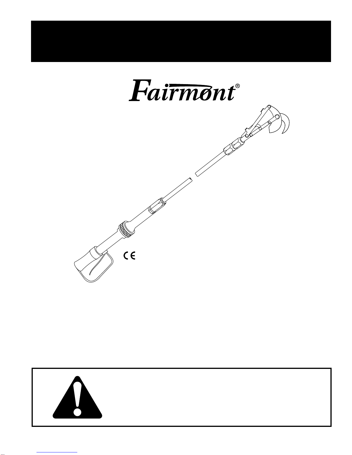
48200, 48520, and 48525 Pruners
Greenlee Textron / Subsidiary of Textron Inc. 74455 Boeing Dr. • Rockford, IL 61109-2988 USA • 815/397-7070
Service (cont’d)
Closure Adjustment
Proper closure adjustment of the cutter is set at the
factory and should not be readjusted until repeated
sharpening of the blade or installation of a new blade
requires it. When open, the flat edge of cutter blade
should be flush with an imaginary line between the two
protrusions on the connector link as shown below.
Flat Edge of
Cutter Blade
Imaginary Line
When closed, the blade should cover 5 mm (3/16") on
the face of the cutter hook.
If the blade is improperly adjusted, blade closure
must be readjusted while the blade is in the fully
open position.
1. Stop the power source and disconnect the tool from
the power source.
2. Loosen jam nut on lower end of outer extension
tube.
• If blade overlaps less than 5 mm (3/16"), or if
blade opening is too great, thread the outer
extension tube further onto the actuator end.
• If blade overlaps more than 5 mm (3/16"), or if
blade is not opening far enough, unscrew the
outer extension tube from the actuator end.
3.Tighten the nut.
Connect the tool to power source and actuate
several times. Blade action should be smooth and
uniform from fully-open position to fully-closed
position [5 mm (3/16") beyond the hook edge]. There
should be no sloppiness in the cutter unit linkage.
Repeat the above procedure until blade closure
is correct.
Troubleshooting
Before You Begin
1. Tool must be connected to the correct power source
system. Refer to the Specifications and Parts
manual for the type of hydraulic system required.
Verify the power source hydraulic system.
2. Verify that the pressure and return hoses are
connected properly to the tool and power source
ports.
3. Power source reservoir must be filled to FULL mark
with hydraulic fluid.
4. Start the power source. All power source shut-off
devices must be engaged or opened (clutch-
engaged, separate ON/OFF valves open, etc.).
5. After verifying all of the above, check the tool to see
if it operates.
If the tool does not operate, it will be necessary
to pinpoint the tool, hose, or power source as the
problem area. The following steps will help to
determine the problem area.
Determine the Problem Area
1. Check the power source and pressure if the proper
gauges and tools are available. If these items are
not available, proceed to the next step.
2. Stop the power source.
3. Disconnect the tool from the hoses and power
source.
4. Connect a known working tool to the hoses and
power source. Refer to the tool’s operator’s manual
for correct hookup procedure. Start the power
source.
• If the known working tool operates, the problem is
in the disconnected tool. Refer to the Trouble-
shooting charts in this manual.
• If the known working tool does not operate, the
problem is likely to be in the hoses or the power
source. Proceed to next step.
5. Stop the power source.
6. Disconnect the existing hoses from the known
working tool and power source.
7. Connect a different set of hoses to the known
operating tool and power source. Start the power
source.
• If the known working tool operates with the
different set of hoses, the problem is in the
disconnected hoses.
• If the known working tool does not operate, the
problem is in the power source. Refer to your
power source operator’s manual for
troubleshooting.