Farm King Allied 2895 Product manual

OperatOr and parts Manual
122011 P4110
2895 Loader
For serial numbers 0528950045 and later


3
Table of Contents - 2895 Loader
Table of Contents
Introduction .................................................................................................................................4
Serial Decal Location...................................................................................................................5
Specifications...............................................................................................................................6
Safety............................................................................................................................................8
• Safety ................................................................................................................................8
• General Safety..................................................................................................................9
• Safety Signs ...................................................................................................................10
• Safety Sign Installation .................................................................................................10
• Safety Decal location..................................................................................................... 11
• Precautions.....................................................................................................................12
Operation ...................................................................................................................................13
• Pre-Operation .................................................................................................................13
• Operation........................................................................................................................14
Maintenance ..............................................................................................................................25
• Lubrication......................................................................................................................25
TSL General Note and Instructions..........................................................................................30
Troubleshooting.........................................................................................................................32
Bolt Torque .................................................................................................................................34
• Checking BoltTorque .....................................................................................................34
Parts............................................................................................................................................36
• Main Frame Assembly Drawing and Parts List............................................................36
• Hydraulic Plumbing Assembly and Parts List..............................................................38
• Main Frame Assembly -TSL Drawing and Parts List...................................................40
• Hydraulic Plumbing Assembly -TSL and Parts List.....................................................42
Assembly....................................................................................................................................44
• Possible Attachment Interference (TSL).......................................................................44
• Cylinder Assembly.........................................................................................................45
Warranty.....................................................................................................................................46
Manufacturer’s statement: for technical reasons Buhler Industries Inc. reserves the right to modify
machinery design and specifications provided herein without any preliminary notice.
Information provided herein is of descriptive nature. Performance quality may depend on soil fertility,
applied agricultural techniques, weather conditions and other factors.

4
Introduction - 2895 Loader
Introduction
Allied by Farm King front-end loaders are backed by years of extensive research. Factory testing
simulates specific operations to evaluate durability; days of continuous cycling in raising, twisting
and dropping loads using a programmed hydraulic power unit represents years of extreme use.
With one of the largest mounting kit application lists in the industry, there is an Allied front-end
loader available for nearly every tractor, large or small, new or old. Custom colors are available to
match all tractor brands which adds resale value and visual appeal.
Keep this manual handy for frequent reference. All new operators or owners must review the
manual before using the equipment and at least annually thereafter. Contact your Allied by Farm
King Dealer if you need assistance, information, or additional copies of the manual. Visit our
website at www.buhlerindustries.com for a complete list of dealers in your area.
The directions left, right, front and rear, as mentioned throughout this manual, are as seen facing
in the direction of travel of the implement.
Terminology
Basic terminology used throughout this manual has been identified below. For part numbers and
further details refer to the Parts section.

5
Serial Decal Location - 2895 Loader
Serial Decal Location
The serial decal is located on the inside left arm of the loader joint plate. Please record the serial
number in the space provided for future reference.The serial decal will provide the model and date
of manufacture of the loader and will be required to obtain correct replacement parts and complete
warranty claims.
For your records, record serial number here:
Warranty Registration:The Warranty Registration and Delivery Report must be completed within
thirty (30) days of delivery to validate the warranty.

6
Specifications - 2895 Loader
Specifications

7
Specifications - 2895 Loader
It. Description 2895E
Reg
2895E
TSL
2895E S
Reg
2895E S
TSL
A Maximum lift height to pivot pin [in/cm] 181/460 181/460 169/429 169/429
BMaximum lift height under level bucket [in/
cm] 172/437 172/437 160/406 160/406
C Clearance with bucket dumped [in/cm] 146/370 146/370 134/340 134/340
D Reach at maximum lift height [in/cm] 29/74 29/74 20/51 20/51
E Maximum dump angle [deg] 62 61 62 61
G Maximum rollback angle [deg] 37 37 37 37
H Digging depth [in/cm] 5.0/12.7 5.0/12.7 5.0/12.7 5.0/12.7
J Overall height in carry position [in/cm] 101/255 103/262 101/255 103/262
ULift capacity to maximum height - at pivot
pin [lb/kg] optional cylinder 7000/3175 6900/3129 6900/3129 6875/3118
VLift capacity to maximum height [lb/kg]
optional cylinder 4950/2245 4950/2245 4925/2234 4925/2234
WLift capacity to 59 in. height - at pivot pin [lb/
kg] optional cylinder 7650/3470 7650/3470 8375/3798 8400/3800
XLift capacity to 59 in. height [lb/kg]
optional cylinder 6125/2778 6125/2778 6600/2993 6600/2993
YBreakout force - at pivot pin [lbf/daN]
optional cylinder 8475/3770 8500/3781 9950/4426 9950/4426
Z Breakout force [lbf/daN] optional cylinder 6550/2914 6550/2914 7450/3314 7475/3325
VV Bucket rollback force at maximum height
[lbf/daN] optional cylinder 6250/2780 6375/2836 6300/2802 6400/2847
XX Bucket rollback force at 59 in. lift height [lbf/
daN] optional cylinder 8000/3559 7850/3492 8000/3559 7875/3503
ZZ Bucket rollback force at ground line
[lbf/daN] optional cylinder 7400/3292 7025/3125 7400/3292 7000/3114
Raising/Lowering time [sec]
optional cylinder 8.1/5.5 8.1/5.5 8.1/5.5 8.1/5.5
Bucket dumping/rollback time [sec]optional
cylinder 4.0/2.6 4.0/2.6 4.0/2.6 4.0/2.6
Lift cylinder tube/shaft size [in]
optional cylinder 3.50/2.00 3.50/2.00 3.50/2.00 3.50/2.00
Lift cylinder stroke/retracted length [in] 32.50/52.50 32.50/52.50 32.50/45.25 32.50/45.25
Bucket cylinder tube/shaft size [in]
optional cylinder 3.00/1.75 3.00/1.75 3.00/1.75 3.00/1.75
Bucket cylinder stroke/retracted length [in] 27.50/38.75 24.50/52.25 27.50/38.75 24.50/52.25
Mounting Height (+/- 3.0) [in] 55
Hydraulic pressure rating/flow rate [psi]/[gpm] 2500/20
Tractor size [H.P. @ normal duty] 130-275
Bucket size [in/cu.ft.]
- * Indicates bucket size used for calculations
of lift capacities and rollback forces.
72/27.0
84/30.5*
96/37.3
Weight (with bkt & mtg kit) [lb/kg] 3800/1270
NOTE: Specifications are subject to change without notice or obligation

8
Safety - 2895 Loader
Safety
Safety Instructions
Remember,YOU are the key to safety. Good safety practices not only protect you, but also the
people around you. Make these practices a working part of your safety program. Be certain that
everyone operating this equipment is familiar with the recommended operating and maintenance
procedures and follows all the safety precautions. Most accidents can be prevented. Do not risk
injury or death by ignoring good safety practices.
The alert symbol is used throughout this manual. It indicates attention is required and identifies
hazards. Follow the recommended precautions.
The safety alert symbol means…
ATTENTION! BECOME ALERT!YOUR SAFETY IS INVOLVED!
CAUTION
The caution symbol indicates a potentially hazardous situation
that, if not avoided, may result in minor or moderate injury. It
may also be used to alert against unsafe practices.
WARNING
The Warning Symbol indicates a potentially hazardous situation
that, if not avoided, could result in death or serious injury, and
includes hazards that are exposed when guards are removed. It
may also be used to alert against unsafe practices.
DANGER
The Danger Symbol indicates an imminently hazardous situation
that, if not avoided will result in death or serious injury. This
signal word is to be limited to the most extreme situations,
typically for machine components that, for functional purposes,
cannot be guarded.

9
Safety - 2895 Loader
General Safety Instructions
• Have a first-aid kit available for use and know how to use it.
• Have a fire extinguisher available, stored in a highly visible location, and know how to use it.
• Wear appropriate protective gear.This list may include but is not limited to:
- hard hat
- protective shoes with slip resistant soles
- protective glasses or goggles
- heavy gloves
- wet weather gear
- hearing protection
- respirator or filter mask
• Read and understand the Operator’s Manual and all safety signs before operating, servicing,
adjusting, repairing, or unplugging the equipment.
• Do not attempt any unauthorized modifications to your Allied by Farm King product as this
could affect function or safety, and could affect the life of the equipment.
• Inspect and clean the working area before operating.
• Keep hands, feet, clothing, and hair away from moving parts.
• Ensure bystanders are clear of the area before operating.
• Improper use of the loader and tractor can cause serious injury or death.
• Operate the loader while seated in the tractor seat only.
• Keep the work area clear of other persons.
• Never leave the tractor unattended while the attachment is raised. Always lower the
attachment to ground and shut tractor off before leaving the tractor seat.
• Never work beneath a raised loader unless it is securely supported.The control lever can be
moved or a hydraulic leak could cause the loader to drop resulting in serious injury or death.
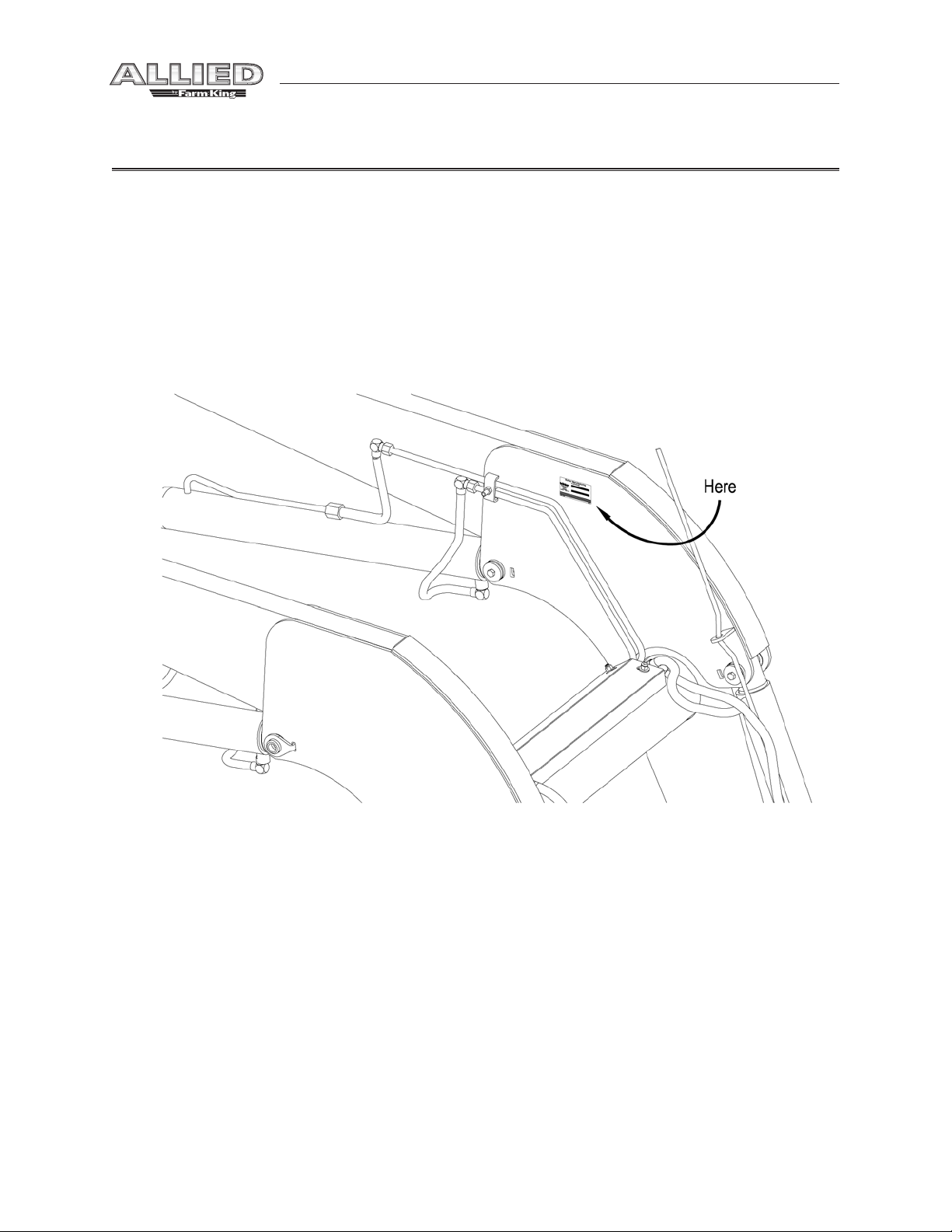
Refer to the Hydraulic Lock Instructions Decal for proper use of the lift locks.
• Prior to use, check to ensure the attachment is properly locked to the quick-tach. Verify from
tractor seat by lowering the attachment to the ground and retracting the lift cylinders.
• Never operate loader with frayed or damaged hoses or leaking fittings. A burst could cause
the loader to drop suddenly and result in serious injury or death and cause damage to the
loader or tractor.
• Keep tractor on solid ground when raising loader. Loose fill rocks and holes can be
dangerous for loader operation and movement.
• If for some reason, you feel the tractor tipping, immediately lower the loader.
• A pivoting front axle acts like a three-wheeled tractor until the stops hit the axle.
• Space rear tires as recommended by the tractor manufacturer. Maximize width for high lift
applications and uneven terrain.
• Add rear ballast as required to ensure 25% of gross vehicle weight is transferred to the rear
axle. Loader, attachment and payload must be included as weight.
• Do not raise attachment to extreme heights while tractor is on an incline. Be alert for terrain
changes and adjust accordingly. Keep attachment at low travel height, no more than one
foot, as long as possible.
• Allow for attachment and loader length when turning.
• The tractor must be equipped with an approved Roll Over Protection Structure (ROPS) and
safety belts.

10
• Use proper lighting and safety warnings when transporting equipment on public roads and
during darkness.The Slow Moving Vehicle (SMV) emblem must be visible. Check with your
local Law Enforcement Agency for specific requirements.
Safety Signs
• The following illustration shows the approximate location and detail of safety signs.
• Keep all safety signs clean and legible and replace any that are damaged or missing.
• When original parts are replaced, any safety signs affixed to those parts should be replaced
as well. Replacement safety signs are available from your local dealer.
Installation
• To install safety signs, ensure the installation area is clean and dry. Decide on the exact
position before you remove the backing paper. Remove the smallest portion of the split
backing paper and align over the specified area. Carefully press in place.
• Slowly peel back the remaining paper and smooth the remaining portion in place. Small air
pockets can be pierced with a pin and smoothed out.
Safety - 2895 Loader

11
Decals provided for both right
hand and left hand (shown)
applications. Item 4 only required
for right hand upright only.
1 - Part # 813689
Safety - 2895 Loader
Safety Decal Locations
1 - Part # 112812
3 - Part # 813439 4 - Part # 813902
5 - Part # 112983 6 - Part # 113711

12
Safety - 2895 Loader
Precautions
The following pictorials indicate important precautions to be used during the operation of the
loader.

13
Operation - 2895 Loader
Operation
Pre-Operation
The following pictorials indicate important precautions to be used during the operation of the
loader.
WARNING
The tractor must be equipped with an approved Roll
over Protection Structure (ROPS) and safety belts to help prevent
personal injury or death caused by tractor roll over.
CAUTION
Maximum rated loader capacity may exceed tractor
rating. Load restrictions or reduction in hydraulic operating
pressure may be required for safe operation.Torque all fittings
and hoses prior to operating loader. Ensure hoses do not rub or
pinch during loader operation.Ty-rap as required.
WARNING Add rear ballast to help prevent personal injury or death
caused by tractor roll over.
Rops: Do not exceed the manufacturer’s rating for maximum gross vehicle weight. Refer to the
Tractor Manual or the ROPS Serial Decal for rating. Do not alter or modify the ROPS structure.
Tractor Tires: Space rear tires as recommended by the tractor manufacturer.Tire inflation and
capacity must meet or exceed additional weight of loader, attachment and payload. Maximize
width for high lift applications.Tread width must not exceed maximum width as recommended in
the Mounting Kit Listing.
Rear Ballast: Rear ballast is required to ensure 25% of gross vehicle weight is transferred to the
rear axle. Attachment and load must be included as weight. Adequate rear weights are required
to counterbalance maximum loader capacity and safe loader operation. Weight can be added as
rear tire liquid (calcium solution), rear wheel weights, rear axle weights and/or three point hitch
mounted ballast or implement. Ballasting will vary with tractor and loader attachment. Refer to
theTractor Manual for recommended ballasting.

14
Operation - 2895 Loader
Operation
General Operating Notes:The following section provides general information that can be applied
towards your specific application. Ensure that you’ve read and understood this manual and your
Tractor Manual. Observe all safety precautions and follow local laws pertaining to the use of your
loader and tractor.
Hydraulics: Under normal conditions, operate the
tractor’s engine at 1/2 throttle.
Note: In cold weather, tractors with load sense hydraulic
systems require longer warm-up periods for the loader
to respond when valve is operated.
In cold weather, operate the tractor’s engine at idle
speed until the hydraulic fluid is warmed up. Slowly
cycle the loader and attachment several times to further
warm the hydraulic fluid. High engine speed when
the hydraulic fluid is cold will cause the pump to wear
prematurely and may cause the loader to operate
erratically.
The hydraulic hoses should be connected to the loader
valve such that when joystick is pulled back the loader
rise and when pushing forward on joystick lowers the
loader. (If joystick is pushed past the detent, the loader
will go in to the float mode.) Move joystick to left to roll
back the bucket an move to the right to dump.
The Allied Remote Hydraulic Control is equipped with
a momentary push button switch and a lock.The push
button is for operating a third function when an electric
diverter is installed.The third function is normally for
operating a grapple. When the button is depressed the
valve ports are open to the grapple cylinders. Shifting
the joystick to the left while button is depressed will
close the grapple and shifting to the right will open.
Important: Always feather the grapple when closing or
opening to avoid unnecessary shock loads on grapple
components.
WARNING Keep grapple closed at all times when bucket is empty and carry
bucket low to the ground. Avoid operating near power wires.

15
All Allied by Farm King hydraulic valves are self-centering and return to neutral from all positions
except float.The float or detent spool is only to be used on the boom circuit.This position allows
the oil to freely flow through the valve so the lift cylinders can extend or retract. It can be engaged
by slightly pushing control beyond full lower. Float will allow for the loader to lower and rise as
the attachment follows the ground contours.To disengage float, slightly pull control back towards
the neutral position.The Allied by Farm King Remote Hydraulic Control can be locked in the neutral
position to minimize unintentional movement.
CAUTION
Lower and dump heavy loads slowly by feathering. Stop tractor
movement gradually. Never drop a loaded attachment and
“catch” hydraulically. Stopping with such downward momentum
may cause damage to the loader or tractor.
When handling heavy loads be sure to raise and lower the loader slowly while leveling the
attachment as required. Feathering can assist in accurately controlling operations by regulating oil
flow through cylinders.
A third function hydraulic control is available for grapple or other hydraulic applications. An
optional divertor valve is connected to the loader attachment spool and is operated via the Allied
by Farm King Remote Hydraulic Control momentary switch and simultaneously engaging the
bucket spool through dump or rollback.
Bucket
When loading a bucket, approach straight and
enter the pile with a level bucket parallel to the line
of motion.
Important: Attempting to turn while loading may
cause damage to the loader or tractor.
Work the controls to raise and rollback the bucket
simultaneously. The combined actions of lift and
bucket cylinders increases loading efficiency and
minimizes resistance to lift.
Note: On tractors with low hydraulic oil flows, both
functions may not be possible
Operation - 2895 Loader

16
Minimize turning angle and length of run between
pile and trailer to increase loading efficiency. Also,
place load evenly or centered in the attachment.
WARNING
Carry the load no higher than necessary to clear the terrain.Turn
and brake slowly. Always be sure that loading area is level and
on solid ground. Do not raise loader higher then required while
dumping. Immediately lower the loader to ground if the tractor
becomes unstable.
Operation - 2895 Loader
Leave material, which drifts over the bucket sides
for final cleanup.
Backfilling or Scraping
For forward back filling, approach pile with a level
bucket. Utilize the float position to minimize bucket
cutting edge wear. Leave dirt in bucket. Dumping
on each pass reduces efficiency.
Note: Use leveling rod for a guide to ensure bucket
is level.
Do not use bucket in dumped position for forward
grading.This will only impose severe shock loading
on the bucket cylinders and it is difficult to maintain
a level grade.

17
Operation - 2895 Loader
For back grading, either load the bucket and
position the heel on the ground or position the
bucket at 40° or less below level as shown. Place
the valve in the float position and back up slowly.
Important: Float position must be used to reduce
down pressure, otherwise cylinder rod(s) and/or
bucket damage could occur.
A Frame:
Regular Duty / Heavy Duty 60"
Both A-frames are for handling medium to
large sized round bales (up to 2000 lbs) when
fitted with two bottom 1240mm long heat treated
spears and two short stabilizers. For pallet
applications with a maximum payload of 4400 lbs
when fitted with the 48.0” pallet fork kit.
Note:The heavy duty frame can also be fitted using
only the one center spear.

18
Operation - 2895 Loader
WARNING Do not operate A Frame for bales without stabilizers.
Handling bales and pallets:
For safe handling of bales and pallets please follow
procedures below:
With a single spear, enter one of the ends of the
bale and drive the spear horizontally into the
center or slightly above center of the bale and
fully penetrate the bale.Then rollback the bucket
cylinders approximately three quarters of the
cylinder stroke and lift bale approximately a foot
off the ground.
With the double or four spears enter the bale
from one of the ends and drive the spear one
third to one half the way up, from the bottom and
fully penetrate the bale.Then rollback the bucket
cylinders approximately three quarters of the
cylinder’s stroke and lift bale approximately
12.0" off the ground.
CAUTION
Never attempt to use the spears as forks, as the spears can easily
penetrate theground causing a spear to bend or break as well
as making the bale unstable to carry. Never attempt to handle
a bale with only part of the spear(s) penetrated.The nut on the
bale spear must be torqued to 500 ft.-lbs. Check the torque
periodically. A loose spear will damage the spear holder.

19
Operation - 2895 Loader
When loading bales onto a trailer, park trailer in
close proximity to minimize turning angle and
length of travel to increase loading efficiency.
As you lift the bale using the regular loader, it is
recommended to feather the valve to allow bucket
cylinders to extend to keep bale at about a 20°
angle. (OnTSL loaders this is not necessary) Lift
the bale only enough to clear the area that the
bale will be placed on. Always approach the trailer
square to the tractor as shown.
CAUTION Avoid sudden stops and sharp turns. Avoid uneven terrain areas
for loading and unloading.
After setting the bale down position the A Frame
with spear(s) horizontal to the ground and slowly
back the tractor straight out.
With pallet forks level and just above the ground,
drive the forks into the pallet completely. Raise
loader to lift pallet and carry level 6 to 12 inches
off the ground. Note:TheTSL loader is highly
recommended when operating with pallet forks
for maintaining a constant level load. Use the level
indicator as a guide to ensure forks are level at
ground.
CAUTION
Avoid sudden stops and sharp turns. Operate at low ground
speeds. Never attempt to lift loads heavier than the rated fork
specs (42" - 2200 lbs) (48" - 4400 lbs). Always lift or carry pallets
using both forks and utilizing the full length of the forks.
WARNING
When driving amongst livestock keep bucket cylinders retracted,
and loader boom at least 6 to 7' off the ground. Store A Frame
away from both play and heavy traffic areas.

20
Operation - 2895 Loader
Grapple:
The grapple is designed to safely prevent loads (bales, silage) from falling out of the bucket. (Refer
to pictorial below for options listed)
WARNING Travel at low speeds. Carry loads as low as possible. Avoid sharp
turns and uneven terrain.
This manual suits for next models
4
Table of contents