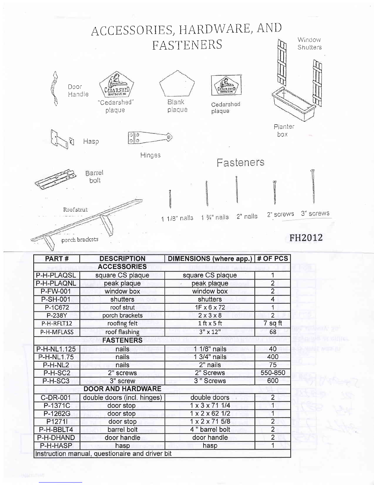
AC C E SS O RIES, HARD\\TARE,
FASTEhIEIi-S AI\D $;'indc"v
Sh uiters
;+
\i
Dcoi-
Handie 'Ceda rsheC
nlrnttp
H'4\irv
i-ldlll.=i
bo;r,
T
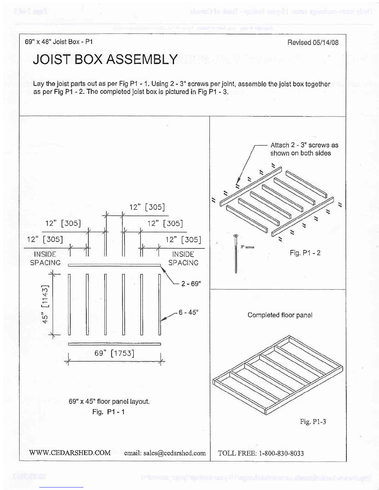
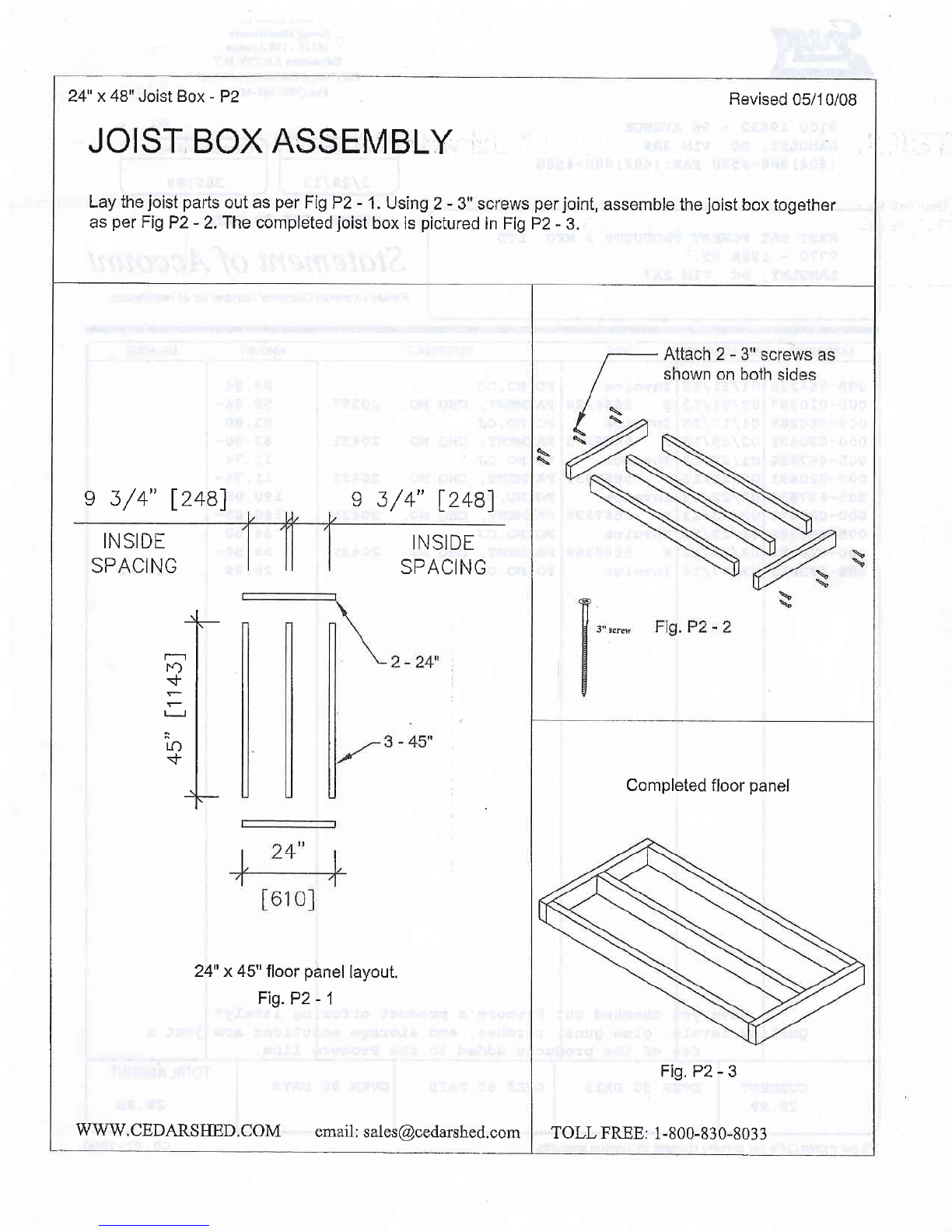
2." sct'e'+ts 3"
f-.linncc
| ,rr ru eJ
i
1 1 /3' nails
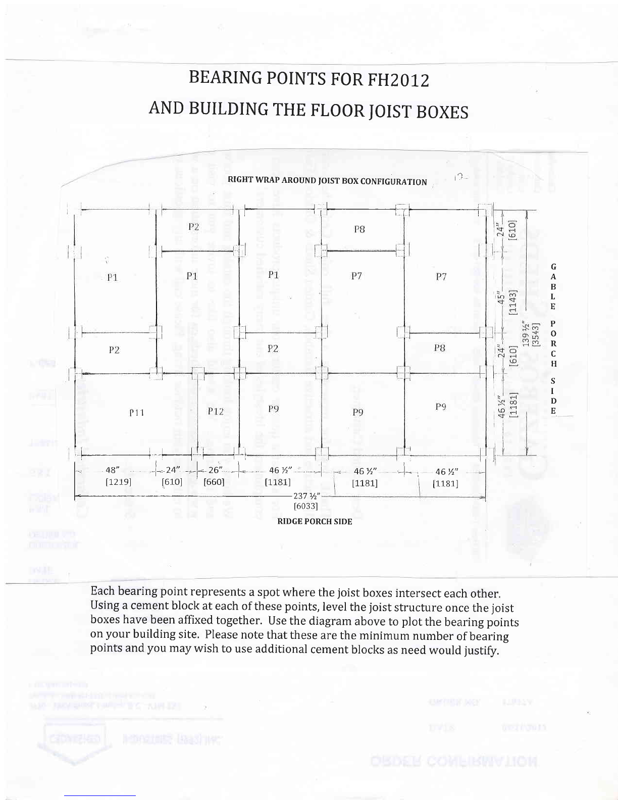
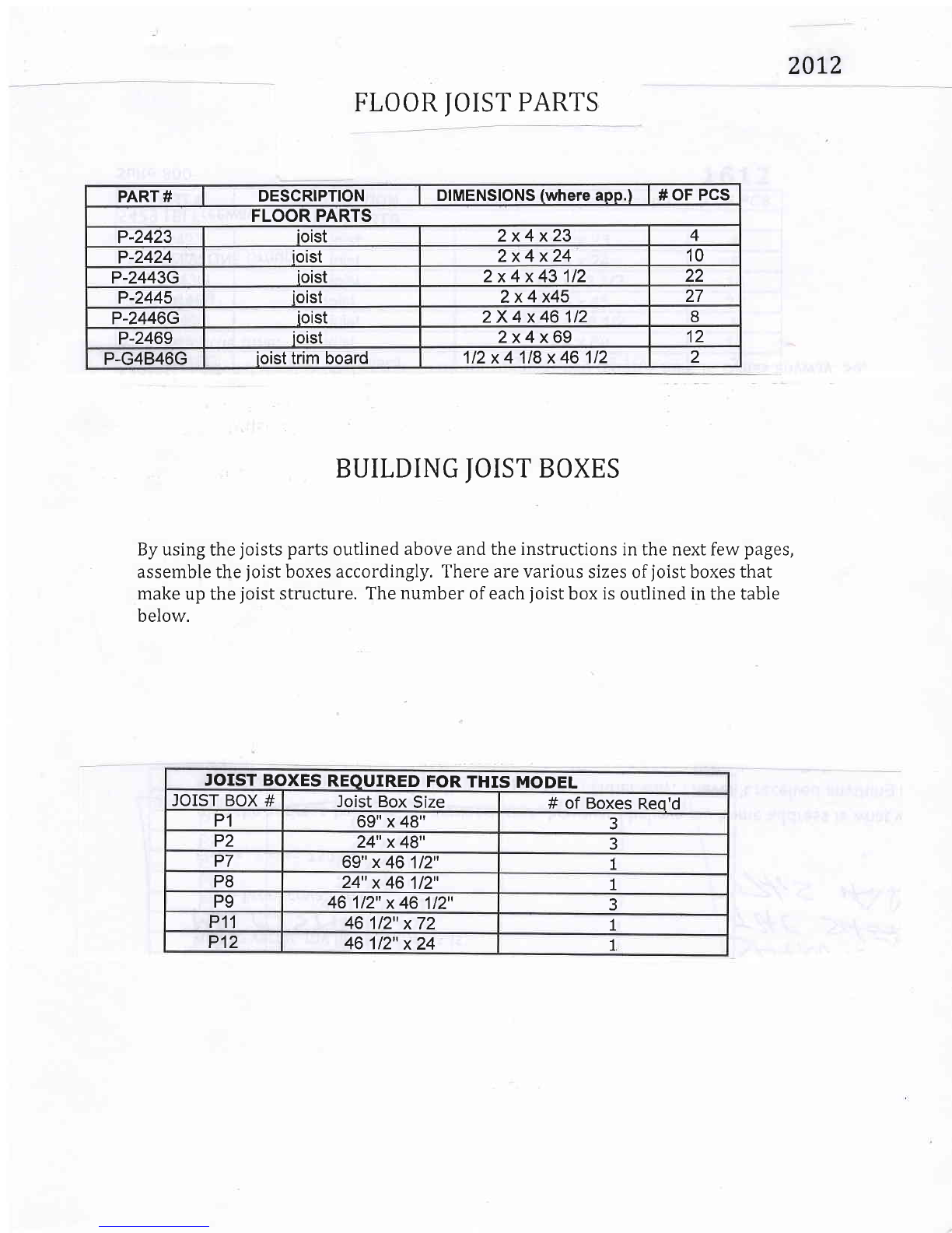
FH2012
pcrch brackets
PART # DESCRIPTION DIMENSIONS (where app.) # OF PCS
ACCESSORIES
P-H-PLAQSL square cs plaque square cs plaque 1
P-H-PLAONL peak plaque oeak olaoue 2
P-FW-001 window box window box 2
P-SH-001 shutters shutters 4
P-1C672 roof strut 1F x6 x72 1
P-238Y porch brackets 2x3x8 2
P-H-RFLT12 roofine felt 1ftx5ft 7sqft
P-H-MFLASS roof flashine 3t'xt2" 68
FASTENERS
P-H-N11.125 nails 1 1/8" nails 40
P-H-N11.75 nails 1 3/4" nails 400
P-H-NL2 nails 2" nails 75
P-H-SC2 2" screws 2" Screws 550-850
P-H-SC3 3" screw 3 " Screws 600
DOOR AND HARDWARE
c-DR-001 double doors (incl. hinges) double doors 2
P-1371C door stop 1x3x71 114 1
P-1262G door stop 1x2x62112 1
P12711 door stoo 1 x2 x71 518 2
P-H-BBLT4 barrel bolt 4 " barrel bolt 2
P-H-DHAND door handle door handle 2
P-H-HASP hasp hasp 1
nstruction manual, questionaire and driver It