FBI Star XL 4800 EZ User manual

STAR XL 4800 EZ’”
Hookup and Installation Instructions
An FBXCompany 100 Engineers Road Hauppauge NY 71788
(516) 582-6161 (800) 645-5430

1. XL4800TM EZ HOOKUP
ZONE HOOKUP
The XL4800EZ contains 16 zones connected as follows;
KEYPAD CONNECTIONS
ZONE TERMINALS ZONF TFRMINALS
1 1 & 2 [Delay] 9 38&39 [Per/m.]
2 3 & 2 [hx FO//j 10 39 & 40 [Pedm.]
3 4 & 5 [Perim.] 11 41 842 [Perim.]
4 6 & 5 [Perim.] 12 42 & 43 [Perim.]
5 7 & 8 [Perim.] 13 44 8 45 [Perim.]
6 9 & 8 [Perim.] 14 45 & 46 [Perim.]
7 lO& 11 [Perim.] 15 48 & 49 [Perim.]
8 12 8 11 [Fire] 16 48 & 49 [Aud. Panic]
The factory default values for each zone is displayed above, and
each zone can be programmed for any of the following types; Delay,
Interior, Interior Follower, Perimeter, Silent Panic, Audible Panic,
Day Trouble, 24 Hour Trouble, or Fire Zone. Each of the zones can
be EOL supervised using the 2.2K EOL resistors provided. The zone
programming questions are questions 35 and 36 within the LCD
keypad programming sequence.
The XL4800 keypads are connected to the control panel with four
conductor cables to terminals 13 through 16. Attach each keypad
used within the system to the terminals as follows;
T13 Red ( + voltage)
T14 Green
T15 Yellow
T16 Black ( - voltage)
The keypads should be connected in parallel at the control panel
with wire runs not to exceed 3000 feet using 22 gauge wire. Keypads
can also be daisy chained, however the maximum sum of the wire
run should not exceed 5000 feet from the control panel using 22
gauge wire. For example, if one keypad is 500 feet from the control
panel with another keypad run 200 feet from the first keypad, this
wire run would be considered 1200 feet (500 to first keypad + 700 to
second keypad).
The available keypad power from connections 13 and 16 is restricted
to 250 ma. Since each keypad draws approximately 60 ma, a
maximum of 4 keypads can obtain their power from these terminals.
Additional key pads must obtain their power from the other auxiliary
panel outputs(if sufficient capacity is available) or an external power
supply. Note: All keypads must be connected to terminals 14 and 15
regardless of where they obtain power.
Auxiliary power (13.8VDC regulated) can be obtained from three
different outputs of the XL4800 EZ panel. The total regulated output
oower from the XL4800 EZ is 900 ma with oower available as
iollows;
TERMINALS MAX. CURRENT APPLICATION
13 (+) 8. 16(-) 250 Ma. Keypads
17 (+) & 16(-) 500 Ma. Misc. (Passives etc.).
33 (+) & 32(-) 150 Ma. Smoke Detectors
NOTE: Terminal 35(+) is internally connected to 17 (+). The
maximum current available from both of these points added together
is 500mA. Power can be obtained from any of these connections
provided that the total does not exceed the rated capacity of the
terminals. Consult the specifications for the devices being connected
to determine the power requirements for your installation.
AUXILIARY POWER
STAR XL4800 EZ INSTALLATION INSTRUCTIONS Page 1
E&MATE CONNECTION
The EZ-Mate Programmer using the model 7170 Product Cartridge
can be used to locally program the english language zone
descriptors for the XL4800 through this modular connector. DO
NOT CONNECT A TELEPHONE LINE TO THIS CONNECTION.
JPl
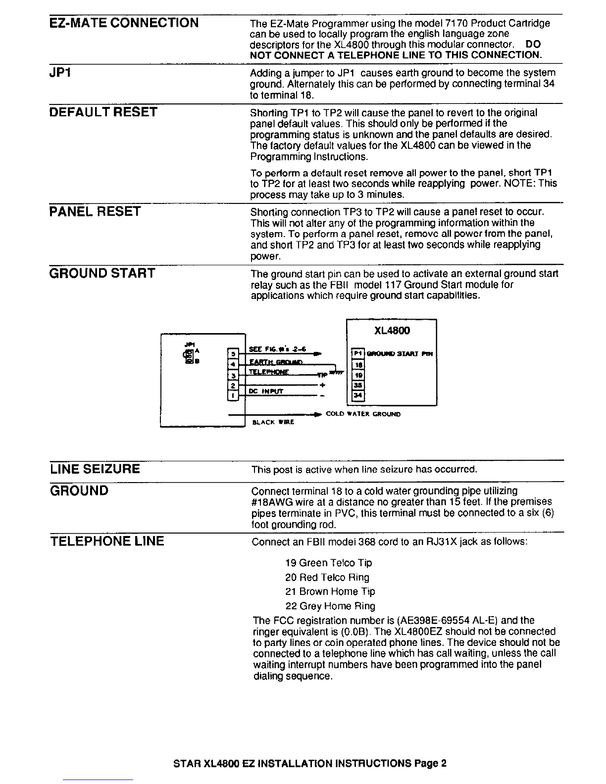
Adding a jumper to JPI causes earth ground to become the system
ground. Alternately this can be performed by connecting terminal 34
to terminal 18.
DEFAULT RESET
Shorting TPl to TP2 will cause the panel to revert to the original
panel default values. This should only be performed if the
programming status is unknown and the panel defaults are desired.
The factory default values for the XL4800 can be viewed in the
Programming Instructions.
PANEL RESET
GROUND START
To perform a default reset remove all power to the panel, short TPl
to TP2 for at least two seconds while reapplying power. NOTE: This
process may take up to 3 minutes.
Shorting connection TP3 to TP2 will cause a panel reset to occur.
This will not alter any of the programming information within the
system. To perform a panel reset, remove all power from the panel,
and short TP2 and TP3 for at least two seconds while reapplying
power.
The ground start pin can be used to activate an external ground start
relay such as the FBI1 model 117 Ground Start module for
applications which require ground start capabilities.
LINE SEIZURE
This post is active when line seizure has occurred.
GROUND
TELEPHONE LINE
Connect terminal 18 to a cold water grounding pipe utilizing
#18AWG wire at a distance no greater than 15 feet. If the premises
pipes terminate in PVC. this terminal must be connected to a six (8)
foot aroundina rod,
- -
Connect an FBI1 model 388 cord to an RJ31X jack as follows:
19 Green Telco Tip
20 Red Telco Ring
21 Brown Home Tip
22 Grey Home Ring
The FCC registration number is (AE398E-89554 AL-E) and the
ringer equivalent is (O.OB). The XL4800EZ should not be connected
to party lines or win operated phone lines. The device should not be
connected to a telephone line which has call waiting, unless the call
waiting interrupt numbers have been programmed into the panel
dialing sequence.
STAR XL4800 Ei! INSTALLATION INSTRUCTIONS Page 2
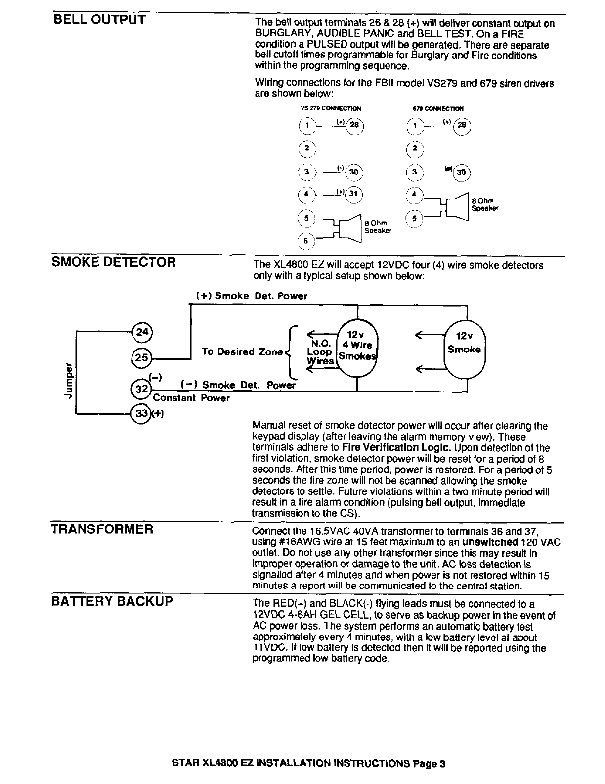
BELL OUTPUT
The bell output terminals 26 6 26 (+) will deliver constant output on
BURGLARY, AUDIBLE PANIC and BELL TEST. On a FIRE
condition a PULSED output will be generated. There are separate
bell cutoff times programmable for Burglary and Fire condftfons
within the programming sequence.
Wirfng connections for the FBI1 model VS279 and 679 siren drivers
are shown below:
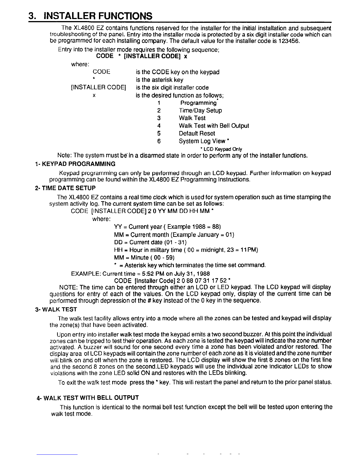
SMOKE DETECTOR
The XL4600 EZ will accept 12VDC four (4) wire smoke detectors
only with a typical setup shown below:
(+I Smoke Det. Power
Manual reset of smoke detector power will occur after clearing the
keypad display (after leaving the alarm memory view). These
terminals adhere to Fire VerlficatlOfl Logic. Upon detection of the
first violation, smoke detector power will be reset for a period of 6
seconds. After this time period, power is restored. For a period of 5
seconds the fire zone will not be scanned allowing the smoke
detectors to settle. Future violations within a two minute period will
resuft in a fire alarm condition (pulsing bell output, immediate
transmission to the CSI.
TRANSFORME usino #16AW
-- ___----___ :R
Connect the 16.5VAC 40VA transformer to terminals 36 and 37,
G wire at 15 feet maximum to an unswltched 120 VAC
out& Do not use any other transformer since this mav resuif in
improper operation or damage to the unit. AC toss detection is
signalled after 4 minutes and when power is not restored within 15
minutes a report will be communicated to the central station.
BAlTERY BACKUP
The RED(+) and BLACK(-) flying leads must be connected to a
12VDC 4-6AH GEL CELL, to serve as backup power in the event of
AC power loss. The system performs an automatic battery test
approximately every 4 minutes, with a low battery level at about
11VDC. If low battery is detected then it will be reported using the
programmed low battery code.
STAR XL4600 EZ INSTALLATION INSTRUCTIONS Page 3

2. KEYPAD MOUNTING
Keypad mounting is identical for both the LED and LCD versions. Keypads can be surface mounted as
follows;
l- Remove both sections of the keypad plastic coverings using a screwdriver in the slots as indicated in the
diagram below.
2- Connect keypad wiring to the control panel.
3. Remove the four screws which secure the keypad to the rear mounting plate.
4- Secure the rear mounting plate to the wall through any of the mounting holes provided.
5. Reconnect the XL4800 keypad to the mounting plate using the screws removed in step 3. Next replace
the keypad plastic sections removed in step I.
NOTE: When selecting the mounting location for LCD keypads it must be noted that the display used is a
top view device which means that the display is best viewed when looking down at the display. Therefore
the location should be selected to optimize the viewing of the display.
KEYPAD ADDRESSING
Both versions of XL4800 keypads (XL4800LED, or XL4800LCD) contain switches to set the address of the
keypad, which identifies the keypad to the control panel. This switch contains 4 locations numbered SW1 -
SW4, and is physically located behind the left hand plastic cover of the keypad. To access this switch, remove
the cover plate by prying the cover open using a screwdriver as shown in the keypad mounting section.
An XL4800 installation can contain a total of eight keypads (4 LED and 4 LCD). Each keypad must be
assigned a unique, sequential address from the table below. For example, if there are 4 LCD keypads and
2 LED keypads, the LCD keypads should be numbered 1,2 ,3, and 4, while the LED keypads should be
numbered 1 & 2.
SW1 -SW3
KEYPAD NUMBER SW1 SW2 SW3
1 ON ON ON
2 OFF ON ON
3 ON OFF ON
4 OFF OFF ON
If the system is programmed for partitioned setup, then there can be a total of 2 LCD and 2 LED keypads
per partition (subsystem). Again there should not be any duplication of addresses between keypads of the
same type. Partition #I can contain keypads 1 & 2 , with partition 2 containing keypads 3 & 4.
SWITCH 4
This switch sets the partttion number: ON = Partition 1, OFF=Pattttion 2. If the system is setup in a non
partitioned manner then SW4 shoutd be ON for all keypads.
STAR XL4800 R INSTALLATION INSTRUCTIONS Page 4
3. INSTALLER FUNCTIONS
The XL4800 EZ contains functions reserved for the installer for the initial installation and subsequent
troubleshooting of the panel. Entry into the installer mode is protected by a six digit installer code which can
be programmed
for
each installing company. The default value for the installer code is 123456,
Entry into the installer mode requires the following sequence;
CODE * [INSTALLERCODE] x
where: CODE is the CODE key on the keypad
t is the asterisk key
[INSTALLER CODE] is the six digit installer code
x is the desired function as follows;
1 Programming
2 Time/Day Setup
3 Walk Test
4 Walk Test with Bell Output
5 Default Reset
6 System Log View ’
* LCD Keypad Chly
Note: The system must be in a disarmed state in order to perform any of the installer functions,
l- KEYPAD PROGRAMMING
Keypad programming can only be performed through an LCD keypad. Further information on keypad
programming can be found within the XL4800 EZ Programming Instructions.
2- TIME DATE SETUP
The XL4800 EZ contains a real time clock which is used for system operation such as time stamping the
system activity log. The current system time can be set as follows:
CODE [INSTALLER CODE] 2 0 YY MM DD HH MM *
where: YY = Current year ( Example 1988 = 88)
MM = Current month (Example January = 01)
DD = Current date (01 - 31)
HH = Hour in military time ( 00 = midnight, 23 = 11 PM)
MM = Minute ( 00 - 59)
* = Asterisk key which terminates the time set command.
EXAMPLE: Current time = 5:52 PM on July 31,1988
CODE [Installer Code] 2 0 88 07 31 17 52 *
NOTE: The time can be entered through either an LCD or LED keypad. The LCD keypad will display
questions for entry of each of the values. On the LCD keypad only, display of the current time can be
performed through depression of the # key instead of the 0 key in the sequence.
3- WALK TEST
The walk test facility allows entry into a mode where all the zones can be tested and keypad will display
the zone(s) that have been activated.
Upon entry into installer walk test mode the keypad emits a two second buzzer. At this point the individual
zones can be tripped to test their operation. As each zone is tested the keypad will indicate the zone number
activated. A buzzer will sound for one second every time a zone has been violated and/or restored. The
display area of LCD keypads will contain the zone number of each zone as it is violated and the zone number
will blink on and off when the zone is restored. The LCD display will show the first 8 zones on the first line
and the second 8 zones on the second.LED keypads will use the individual zone indicator LEDs to show
violations with the zone LED solid ON and restores with the LEDs blinking.
To exit the walk test mode press the * key. This will restart the panel and return to the prior panel status.
4-WALK TEST WITH BELL OUTPUT
This function is identical to the normal bell test function except the bell will be tested upon entering the
walk test mode.
STAR
XLABM
EZ
INSTALLATION
lNSTRUCTlONS
Pane
5
5- DEFAULT RESET
The XL4800 EZ is shipped from the factory with default values which can be viewed within the
Programming Instructions. The DEFAULT RESET function will return the system lo these original default
values, overwriting any values modffied by programming.This procedure may take as long as 30 seconds as
the default values are being read into the panel. After completion the panel will reset and return to the current
panel status.
This function can also be performed by shorting the DEFAULT RESET (TPl. TP2) pins directly on the
control board.
6-SYSTEM LOG VIEW
The XL4800 EZ contains a feature which retains the last 128 events. This system event log can be read
directly through an LCD keypad or retrieved remotely by an EZ-Mate PC Downloader.
NOTE: The system log can not be read through an LED keypad.
Entry into the system log view will obtain the most recent entry into the system log. Depression of the
STAY key will advance backwards through the events until the oldest event is obtained. Depression of the
BYPASS key will scan through the list in reverse order.
The list below displays the possible events which may appear on the LCD display. This represents the
information appearing on the second line of the LCD display, the first line contains the time and date of the
entry. Note: The items shown in lower case letters will contain the actual zone number or partition based on
the type of message.
LOG MESSAGE EXPLANATION
ALARM Keyp pz p Keypad emergency conditions. pz = keypad condition 1-4, p=partition
ALARM Zone zn p Zone alarm zn= actual zone, p= partition
TROUBLE zn p Trouble condition zn= actual zone p = partition
BYPASS us zn p Bypass us = user performing the bypass, zn= zone bypassed, p=partition
RESTORE 2 zn p Restore of zone. zn= actual zone, p= partition
SYS TRBL System trouble such as AC loss, Low Battery or System Error
SYS RSTR System restore of condition such as AC Loss, Low Battery, System Error.
OPENING us p Opening us= user performing the opening p=partition
CLOSING us p Closing us = user performing the closing p= partition
CODE/RESET xx p System abort or user code entered to leave alarm view mode
CS TEST System test transmitted to Central Station
DOWNLOAD Indicates that a download has taken place.
AMBUSH US p Indicates that an ambush code has been entered us = user number p =
partition
CALLBACK Request Indicates that a remote communications session requiring a callback was
made.
Clock Set Indicates system time/date waschanged. The entry on thefirst linedisplays
the revised system time.
ANSWERED telcall Shows that the XL4800EZ has picked up the telephone line in response to
a remote communication request.
ENDED Telcall Indicates that a remote communications session has ended.
Upon completion of the system log view depress the * key to exit. This will terminate the system log view
and return to the previous panelstatus.
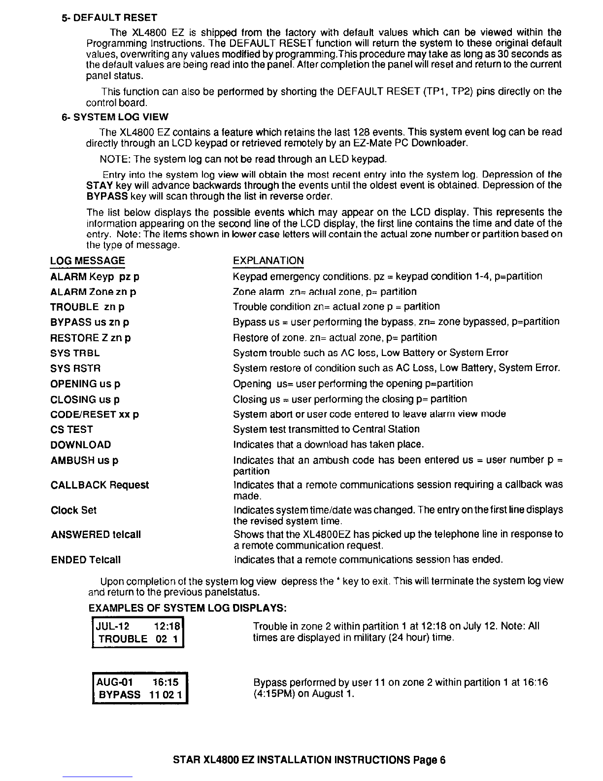
EXAMPLES OF SYSTEM LOG DISPLAYS:
Trouble in zone 2 within partition 1 at 12:18 on July 12. Note: All
times are displayed in military (24 hour) time.
Bypass performed by user 11 on zone 2 within partition 1 at 16:16
(4:15PM) on August 1.
STAR XL4800 EZ INSTALLATION INSTRUCTIONS Page 6

4. XL4800 EZ KEYPAD FUNCTIONS SUMMARY
END USER FUNCTIONS
PROCEDURE KEY SEQUENCE
ARM SYSTEM [USER]
STAY STAY [USER]
INSTANT INSTANT [USER]
INSTANT-STAY INSTANT STAY[USERl or STAY INSTANT LUSERI
BYPASS BYPASS [ZNl
BYPASS
multiple
BYPASS [ZN] BYPASS [ZNl BYPASS [ZNI ......
UNBYPASS BYPASS [ZNl
UNBYPASS
multiple
BYPASS [ZN] BYPASS [ZNl BYPASS IZNI......
FORCED ARMING #2
DISARM [USER]
USER DEFINITION CODE[USERl[US#tl[US#l[USIDlHJSIDl~LEVlILEVl
MULTI-PARTITION # 0 [USER] p
QUICK ARM #l
TIME/DATE SET #3OYYMMDDHHMM
ZONE DIRECTORY * #4
CHIME MODE
#6
INSTALLER FUNCTIONS
PROCEDURE
KEYPAD PROGRAMMING*
EXIT PROG.MODE
TIME/DATE SETUP
WALK TEST w/o BELL
WALK TEST
with
BELL
DEFAULT RESET
SYSTEM LOG VIEW*
*LCD Keypad Only
KEYPAD EMERGENCY CONDITIONS
KEY SEQUENCE
CODE * [INSTALLER CODE1 1
* + # (Together)
CODE * [INSTALLERCODE] 2
CODE * [INSTALLERCODEI 3
CODE * [INSTALLERCODE] 4
CODE * [INSTALLER CODE] 5
CODE
* [INSTALLERCODE] 6
1 PANIC1
-iUX.
STAR XL4800 EZ INSTALLATION INSTRUCTIONS
Page 7
Table of contents
Other FBI Security System manuals


