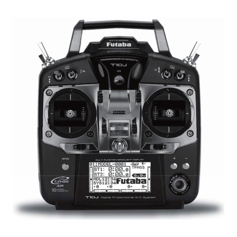
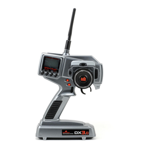
FD-RC Fly-Dream F6TB Assembly instructions

www.fd-rc.com
F6TB Manual
6 Channel 2.4GHz Radio System

FLY-DREAM 2W W W. F D -RC.COM
Contents
1 Preface……………………………………………………………………………3
1.1 Important statement………………………………………………………3
1.2 Safety notice………………………………………………………………3
1.3 Attention before flight………………………………………………3
2Item Specification and Features………………………………………………4
2.1 Packing List………………………………………………………………4
2.2Transmitter F6TB…………………………………………………………4
2.3Receiver IS-6R…………………………………………………………4
3Operation Panel………………………………………………………………………5
3.1 Front of F6TB……………………………………………………………5
3.2 Back of F6TB……………………………………………………………5
3.3 Receiver IS-6R Graphical……………………………………………5
4System Menu…………………………………………………………………………6
4.1 Model Choice………………………………………………………………6
4.2 Channel Reverse……………………………………………………………7
4.3 Dual Rate D/R………………………………………………………………7
4.4 Mixing………………………………………………………………………7
4.5 Battery Type… … …………………………………………………………9
4.6 Bind…………………………………………………………………………9
5Special Features Menu……………………………………………………………………10
5.1 Timer………………………………………………………………………10
5.2 Transmitter P ower………………………………………………………10
6Stick Mode and Country Selection………………………………………………11
6.1 Stick Mode…………………………………………………………………11
6.2 Country Selection………………………………………………………12
7 Failsafe…………………………………………………………………………12
8 Simulator Mode…………………………………………………………………12

FLY-DREAM 3W W W. F D -RC.COM
1 Preface
1.1 Important statement
1) The transmitter should be used only by experienced pilots at least 14 years old.
2) Model aircraft should be flown only in approved areas.
3) Fly Dream is not responsible for safety issues caused by use of the transmitter after it is sold.
4) Our distributors are responsible for technical support and service after sale. Please contact
the local distributor for solutions to problems caused by usage, operation, maintenance, etc.
1.2 Safety notice
1) Stay far away obstacles and people
RC aircraft in flight can cause a number of potential risks. Please keep your radio controlled
aircraft well away from people, high buildings, high-tension power lines, etc., and avoid operating
in rain, storms, or thunder and lightning.
2) Avoid humid environments
Radio systems should be kept away from humidity and vapor because it is composed of
complicated precise electronic elements and mechanical parts.
3) Proper operation
Use original spare parts to upgrade, modify or maintain your equipment in order to ensure its
proper operations and safety. Please operate your equipment within the permitted range of
functions. It is forbidden to use the equipment except in accordance with relevant safety laws
and regulations.
4) Safe operation
Use your equipment according to your body status and flight skills. Fatigue, listlessness and
careless operation will increase the possibilities of accidental hazard.
5) Avoid heat sources
The transmitter is composed of precise electronic components and mechanical parts. Keep it
away from heat sources and sun to avoid distortion or damage caused by high temperature.
6) Supply correct power
Please read the voltage ranges of the transmitter and receiver from the manual and avoid
applying higher voltages.
1.3 Attention before flight
1) Ensure that the battery packs of both transmitter and receiver are fully charged.
2) Ensure that the receiver is bound to the transmitter and that failsafe has been set up
correctly (especially that throttle failsafe is set to idle).
3) Set both throttle stick and throttle trim of F6TB at the lowest positions before operation.
4) When starting a flight, turn on the F6TB first, and connect the battery to the aircraft last.
When finished, disconnect the aircraft battery first, and turn off the F6TB last.
5) Check that all the servos in the RC aircraft move in the correct direction and amount in
response to the transmitter. Broken or improperly set up servos can result in unforeseen
dangers.

FLY-DREAM 4W W W. F D -RC.COM
2 Item specification and features
2.1 Packing List
2.2 Transmitter F6TB
Channel
1-6CH
Power
≤100mW
Frequency range
2.4GHz-2.483GHz
Operating voltage
3.7V-8.4V
Spread Spectrum
FHSS
Operating current
≤200mA
1) The first choice of transmitter for fixed wing planes.
2) Innovative system for quickly changing stick mode.
3) Perfectly designed in accord with human engineering, unique comfortable handle design.
4) Antenna is collapsible, easy to carry and convenient for packing.
5) Clear and legible screen for easy and convenient programming.
6) Uses 2.4G FHSS protocol, compatible with FLY-DREAM V3 system.
7) Transmitter output power adjustable to conserve battery power and allow range checking.
8) Eight model memories for fixed wing planes.
9) Digital electronic trim, with on-screen display and audible indication.
10) Low voltage design works on 1s lithium battery, 2s lithium battery or 4 cell alkaline/Ni-MH/
Ni-Cd battery.
2.3 Receiver IS-6R
Channel
1-6CH
Operating voltage
4.8V-6.0V
Frequency range
2.4GHz-2.483GHz
Output pulse
1000-2000μs
Dimension
34.2×18.4×8.7mm
Resolution
1μs
Weight
6.5g
Range
>
500m(on ground)
1) Small, light design.
2) Failsafe with preset servo positions to protect your plane in case of signal loss
3) Hidden bind/FS switch to prevent accidental use
4) High sensitivity, long range
User
manual
T
ransmitter
Battery holder
Receiver

FLY-DREAM 5W W W. F D -RC.COM
3 Operation Panel
3.1 Front of F6TB
3.2 Back of F6TB
3.3 Receiver IS-6R Graphical
Channel Meaning
BAT Battery channel
CH6 Flap
CH5 Landing Gear
CH4 Rudder
CH3 Throttle
CH2 Elevator
CH1 Aileron
Bind button under "V3"
Indicating lamp
Note the polarity

FLY-DREAM 6W W W. F D -RC.COM
4 System Menu
Make sure the throttle stick is at idle (down) and turn on the transmitter. The screen display
version information and after 0.5s it will show the information below:
Press ENTER for long time and enter menu setting interface.
Press ENTER a short time, the ENTER button selects in turn each of the six setting screens
(model choice, channel reverse, dual rate D/R, mixing, battery type and bind).
Note: If the throttle stick is not at idle when the transmitter is turned on, the buzzer will
beep rapidly and the screen will display “CH3_” (to indicate throttle channel). If plug into
imitator, screen display “PPN” at electricity display position. Please reference to “8
Simulator mode.”
4.1 Model Choice
Press the button of ENTER and gets into model choice interface, screen will display as:
4.1A. Use the UP and DOWN buttons to change the model number.
A model name of up to four characters can be entered for each model number by pressing EXIT
and using the UP and DOWN buttons; press EXIT again to move to the next character.
Press the ENTER button to move to the Channel Reverse screen.
4.1B. If you press “EXIT”, the program into the model name change interface, model name
initials flashing, through the "UP" or "DOWN" key to realize character change, through the
"EXIT" button to switch to the next letter. Model name only has four characters, when switching
to the last character, press "EXIT" button again, model name letters to stop flashing. Program
gets into 4.1 A.
There are 8 models for choosing, model name has 4 letters, they can be the letter or be digital,
still can default. Specific letters atlas as follows, a total of 27 characters (including the default):
Tx voltage
Trim indicators
Model
Tx battery state
Model name
Model

FLY-DREAM 7W W W. F D -RC.COM
4.2 Channel Reverse
Press ENTER and gets into Channel Reverse interface, screen display as :
Press DOWN to change the channel. Press UP to change the channel reverse setting.
Press ENTER to save the settings and move to the D/R Screen.
4.3 Dual Rate (D/R)
Press the button ENTER gets into Dual Rate (D/R )setting interface, screen will display as:
Press EXIT to change the channel number. Press UP or DOWN to change the percentage D/R
value. When finished, press ENTER to save settings and go to the Mixing interface.
The F6TB transmitter provides dual rate (D/R) on three channels (CH1, CH2 and CH4). The D/R
switch sets all three channels simultaneously to either high rate (100%) or low rate (the D/R
settings). Switch UP gives high rate, switch DOWN gives low rate.
Press UP or DOWN
to change %
Press EXIT
to change channel
Press DOWN
for channel
Press UP
for reverse

FLY-DREAM 8W W W. F D -RC.COM
4.4 Mixing
Press ENTER button and gets into “Mixing” interface,screen display as:
This menu provides a choice of three mixes, as follows:
FLAPERON MIX (Channels 1-6)
Adds flap function to dual aileron servo setup.
Moving the aileron stick to the right causes right
aileron to go
up, left aileron down. Moving
Channel 6 switch causes both to go down (flap).
Flap action is adjustable. Right servo connects
to CH1, left servo to CH6.
V-TAIL MIX (Channels 2 - 4)
Used for V tail aircraft. Mixes
elevator and
rudder inputs for pitch an
d yaw control. Left
control surface servo connects to CH2, right to
CH4.
ELEVON MIX (Channels 1 - 2)
Used for delta wing aircraft and others requiring
elevon control. Mixes aileron and elevator inputs
for roll and pitch contr
ol. Left elevon servo
connects to CH1, right servo to CH2.
Press ENTER to open the Mixing interface screen display and use UP or DOWN to select from
among the mixes, as shown below (only one mix can be selected at a time):
The Elevon mix (1 - 2) and the V-tail mix (2 - 4) are either on or off and are not adjustable.
The Flaperon mix (1 - 6) can be varied. To adjust to ratio of flap function to aileron, press EXIT
while 1 – 6 is on screen. By default, the ratio is set at 0% (i.e., no flap action). Using UP and
DOWN, the ratio can be varied between -100% and +100%, allowing the flap action to be set to
an appropriate amount in the correct direction. After adjusting, press EXIT to save the flap ratio
setting.
Press UP or
DOWN

FLY-DREAM 9W W W. F D -RC.COM
Press ENTER to save the mix setting and get into the “Battery Type” interface.
Note: If a mix does not work in the correct direction, try reversing the channels involved
and also interchanging the servo plugs.
4.5 Battery Type
The F6TB can use various types of battery. This interface offers a choice of three voltage levels
to allow the low voltage alarm to be set correctly.
Press ENTER to open the Battery Type menu (“LowP.”), which offers the following choices:
The choices are: 1s lithium battery (1c.LP), 2s lithium battery (2c.LP), or 4 cell battery (4c.NH).
The 4-cell battery can be made up of dry cells (alkaline), Nickel Metal Hydride (NiMH), or Nickel
Cadmium (NiCd).
Setting to the appropriate type of battery ensures that the low battery alarm voltage will be
triggered at the correct value to prevent over-discharge or loss of transmitter function.
After selecting, press ENTER to save the setting and enter the Bind interface, or press EXIT.
Press UP
for positive
Press UP or
DOWN
Press DOWN
for negative
Press EXIT

FLY-DREAM 10 WWW.FD-RC.COM
4.6 Bind
Press ENTER to open the Bind interface screen:
Press UP or DOWN to put the transmitter into bind mode, as indicated by the dashes moving
across the screen. This causes the transmitter to send information about its ID code.
To bind the IS-6R receiver, hold the button under the “V3 thumb” symbol while applying power.
The red receiver LED will light. Release the button immediately. The red LED will flash 6 times to
indicate bind success. Turn off the receiver.
Press EXIT three times to return the transmitter to normal working state. Turn on the receiver
and it should respond normally.
Note: Once the receiver is bound, it will initialize automatically. Since binding clears all
failsafe information, after binding it is necessary to reset the failsafe (see section 7).
5 Special Features Menu
To open the Special Features Menu, press and hold ENTER while turning on the transmitter.
This enables setting of the Timer and Transmitter Power functions.
5.1 Timer
For the timer setting interface, press the ENTER button. The screen will display the model
number and the timer setting in minutes. The screen will show something like the following:
Press ENTER
for Timer setting
Press EXIT
for Power setting
Press ENTER
Press UP or
DOWN
Press UP or
DOWN

FLY-DREAM 11 WWW.FD-RC.COM
This means that for model number 1 the timer is set for 1 minute. Press UP or DOWN to change
the timer setting. Press ENTER to change the model number.
After timers are set, press EXIT to save the settings and return to the Special Features menu.
To use the timer, put the Timer Switch in the DOWN position. The screen will show:
Raise the throttle stick to start the timer. Returning the throttle stick to idle pauses the timer. The
timer will count up until the set value is reached, when the buzzer will begin slow beeping. To
stop the beeping and reset the timer, place the Timer Switch in the UP position.
5.2 Transmitter Power
For the Transmitter Power screen, press EXIT. This will display the current setting value. The
F6TB transmitter can be set to a power value of 20dBm, 17dBm, 14dBm, 10dBm, or 0dBm.
Maximum power is 20dBm. Press UP or DOWN to change the power value.
After power is set, press ENTER to save the setting and return to the interface.
To check operation of the system, set power to 0dBm and conduct a range test. Range at
20dBm will be approximately ten times that measured at 0dBm.
6 Stick Mode and Country Selection
Press ENTER and EXIT at the same time and turn on the transmitter. There is now a choice
between the Stick Mode screen and the Country screen, as follows:
Press EXIT
for Country
Press ENTER
for Stick Mode
Press UP or DOWN

FLY-DREAM 12 WWW.FD-RC.COM
6.1 Stick Mode
Press ENTER to open the Stick Mode screen. There are four possible transmitter stick modes:
below.
Modes 1 and 3 have throttle (no centering) on the right stick and elevator (spring centered) on
the left. Modes 2 and 4 have throttle on the left and elevator on the right.
The F6TB transmitter has a unique mechanical switch on the back of the transmitter to make
mode change quick and easy. In “Mode 1” position it configures the sticks for Modes 1 and 3.
Sliding the switch to “Mode 2” configures throttle and elevator for Modes 2 and 4.
To set the transmitter mode, make sure the Mode Change switch is in the correct position. Then
press UP or DOWN to change the Stick Mode setting on screen.
When finished, press the EXIT button to save the setting and return to “Mode choices” interface.
6.2 Country Selection
To open the Country screen, press EXIT while in the Mode Choice interface.
The Country screen is needed because France only allows a portion of the 2.4 GHZ band to be
used for radio control purposes. The choice is:
“CU - 0”, the international general frequency range.
“CU - F”, France frequency range.
Choose International, unless the transmitter is to be used in France.
Press ENTER to save the setting and return to the “Mode choices” main interface.
Press UP or DOWN
Press UP or DOWN
Switch to MODE1
position
Switch to MODE2
position
Press UP or DOWN

FLY-DREAM 13 WWW.FD-RC.COM
7 Failsafe
The Failsafe function is activated when the receiver loses signal. This can happen for a number
of reasons, including: electromagnetic interference, excessive distance, low transmitter battery,
etc. Setting the failsafe ensures that in such a situation the servos and ESC return automatically
to the pre-set values. Most important is that on loss of signal the throttle goes to zero.
To set failsafe on an IS-6R receiver (receiver must be already bound to the F6TB):
1) Turn on F6TB.
2) Press and hold the button on the receiver (under the “V3 thumb” symbol) while connecting
the receiver to the battery. The LED on the receiver will light for about one second and then
go out. Release the receiver button while the light is on (if necessary, do the whole process
again).
3) Move the sticks on your transmitter to the desired failsafe positions in the event of lost signal.
Press the button on the receiver .The LED will flash several times; this shows the receiver
has remembered the set positions. In the rare event that the system loses signal, all
channels will return to these positions.
4) Turn off the power to the receiver. Failsafe is now set.
8 Simulator Mode
Insert the simulator cable plug (3.5mm) into the F6TB D.S.C. socket. The screen will display as:
In this configuration, the F6TB does not transmit. Instead, its PPM signal is sent to the computer
to control a flight simulator.
Table of contents
