FDS FD102CV-LP-S User manual
Document Number:
MAN –FD102CV-LP-S
Rev:
A
Revision Date:
11/17/2010
Page 1 of 15
©2015 Flight Display Systems.
All Rights Reserved.
TECHNICAL SUPPORT
470-239-7421 or FlightDisplay.com
Installation and Operation
Manual
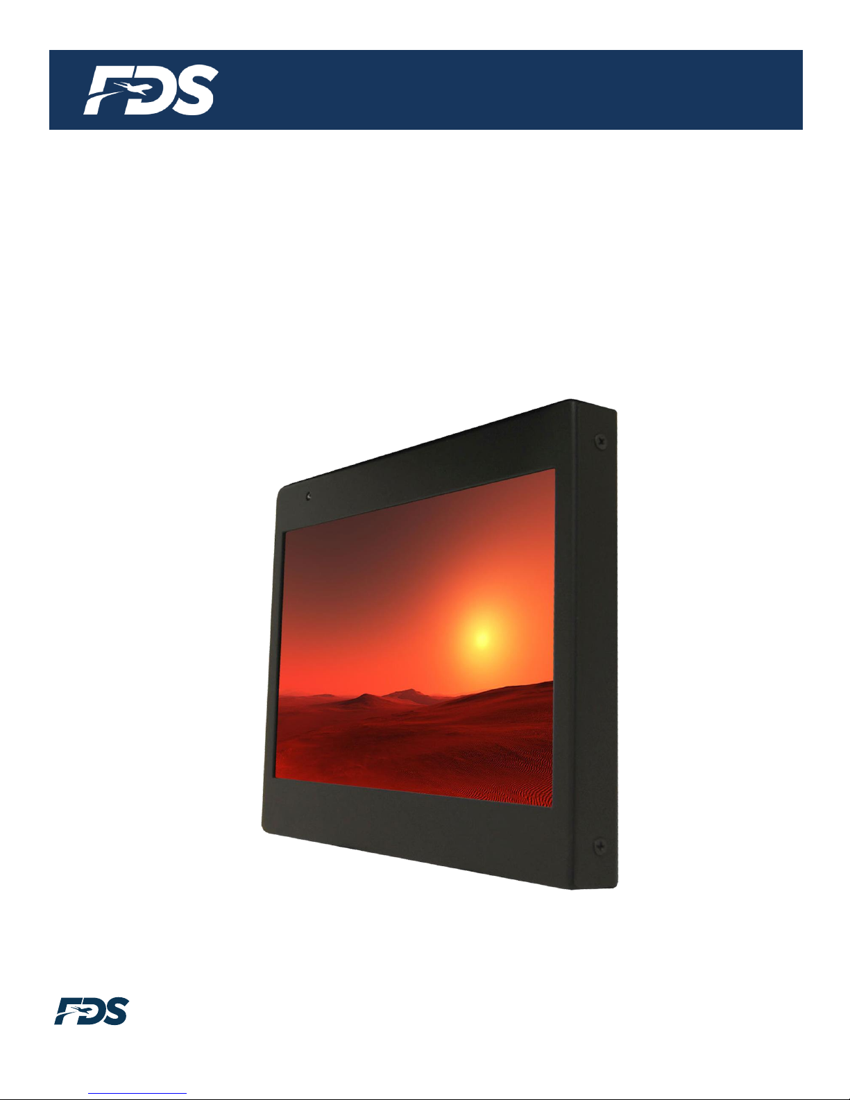
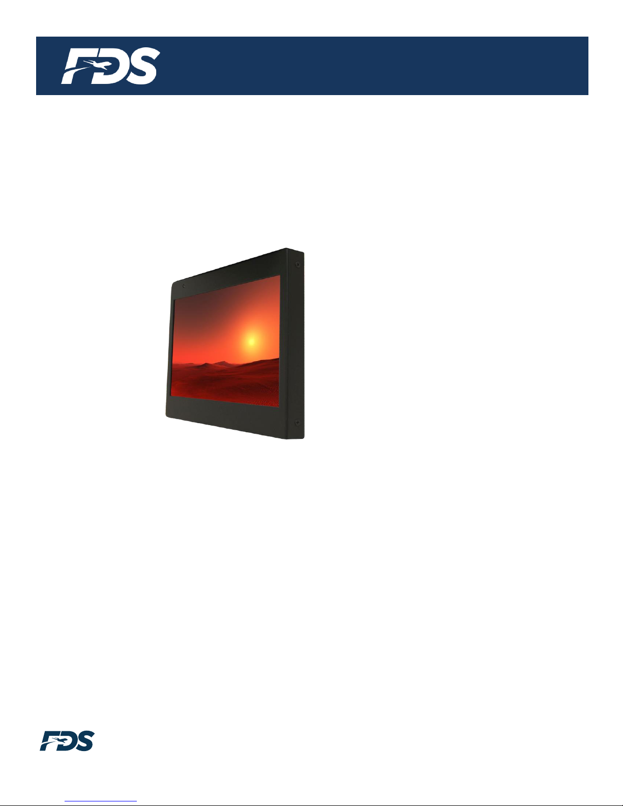
FD102CV-LP-S
Low Profile 10.2” Widescreen LCD

Document Number:
MAN –FD102CV-LP-S
Rev:
A
Revision Date:
11/17/2010
Page 2 of 15
©2015 Flight Display Systems.
All Rights Reserved.
TECHNICAL SUPPORT
470-239-7421 or FlightDisplay.com
FD102CV-LP-S
Low Profile 10.2” Widescreen LCD
© 2010 Flight Display Systems. All Rights Reserved.
Flight Display Systems
6435 Shiloh Road
Alpharetta, GA 30005
470-239-7400 Phone
678-867-6742 Fax
www.FlightDisplay.com
For the most current copy of all product manuals, please visit our website at
www.FlightDisplay.com

Document Number:
MAN –FD102CV-LP-S
Rev:
A
Revision Date:
11/17/2010
Page 3 of 15
©2015 Flight Display Systems.
All Rights Reserved.
TECHNICAL SUPPORT
470-239-7421 or FlightDisplay.com
Table of Contents
General Information......................................................................................................................4
Front View......................................................................................................................................4
Additional Information................................................................................................................4
Specifications................................................................................................................................5
Installation Instructions .............................................................................................................5
Power ..............................................................................................................................................5
Wiring Instructions......................................................................................................................6
Composite and Audio Wiring.....................................................................................................6
VGA Wiring...................................................................................................................................7
Power & Ground Wiring..............................................................................................................7
Power/Video .................................................................................................................................8
Operations Instructions ..............................................................................................................9
Button Control...............................................................................................................................9
Remote Control Buttons.............................................................................................................10
Troubleshooting.........................................................................................................................11
Technical Support......................................................................................................................12
Instructions for Continued Airworthiness ...........................................................................12
Warranty ......................................................................................................................................13
Installation Drawings ...............................................................................................................14
Log of Revisions.........................................................................................................................15
Document Number:
MAN –FD102CV-LP-S
Rev:
A
Revision Date:
11/17/2010
Page 4 of 15
©2015 Flight Display Systems.
All Rights Reserved.
TECHNICAL SUPPORT
470-239-7421 or FlightDisplay.com
General Information
This high resolution Low Profile 10.2” Widescreen LCD is built with retrofit aircraft
integration in mind, this display can switch between three video input sources using an
infrared remote or the control buttons on the bottom face of the unit. It is perfect for cabin
video and graphical entertainment. The FD102CV-LP-S has features that allow installation
in the smallest of mounting areas with the minimum of interface equipment.
Front View
Additional Information
The 10” Widescreen LCD utilizes a state of the art digital video decoding chipset for the
analog video input. The three video sources in order of picture quality are VGA (computer
graphics, like Moving Maps), and two (2x) Composite Video (DVD, Camera or VCR). Both
NTSC and PAL formats are auto-detected.
The FD102CV-LP-S can also be connected to existing video switchers and can take a
composite video input from a selector interface box. In this case, multiple input sources
can be selected and displayed on the monitor.

Document Number:
MAN –FD102CV-LP-S
Rev:
A
Revision Date:
11/17/2010
Page 5 of 15
©2015 Flight Display Systems.
All Rights Reserved.
TECHNICAL SUPPORT
470-239-7421 or FlightDisplay.com
Specifications
Display Type
10.2” Widescreen TFT Color LCD
Pixel Pitch
0.072 mm X 0.220 mm
Screen Resolution
1024 x 600
Supported Resolution
Up to 1600 x 1200
Brightness
300 cd/m²
Contrast
500:1
Display Dimension
9.55”(W) x 7.30”(H) x 0.80”(D)
Display Size
8.67”(W) x 5.12”(H)
Weight
2 lbs 7 oz
Power
28VDC @ .3 Amps
Operating Temperature
-20°C/60°C
Storage Temperature
-30°C/70°C
PC & Video Input
SVGA (Analog RGB 15 pin D-sub),
2 Composite Video
Screen Control
On Screen Display Menu
Remote Control
IR, included
Materials
Aluminum
DO-160 TESTED
Section 21, Category B
Installation Instructions
All cabin entertainment equipment, such as the FD102CV-LP-S, should be installed on a
non-essential bus and have a dedicated circuit breaker. It is a requirement that a switch
be installed in the cockpit so that the pilot can de-energize the entertainment system
should it become necessary. See mounting specification drawing MSD-129 at end of
manual.
Power
This is a 28VDC monitor that requires .3 Amps of power to operate. The unit turns on
automatically upon power application.

Document Number:
MAN –FD102CV-LP-S
Rev:
A
Revision Date:
11/17/2010
Page 6 of 15
©2015 Flight Display Systems.
All Rights Reserved.
TECHNICAL SUPPORT
470-239-7421 or FlightDisplay.com
Wiring Suggestions
All shields should be grounded to the connector at the source, and floating at the display.
Avoid routing video wiring parallel to:
AC wiring
Strobe wiring
DC motor supply cables
Inverter cabling
Or any other potential noise source.
Composite and Audio Wiring
Recommended cable for s-video/composite and audio purposes is PIC 75 Ohm Coax,
P/N V75268. This is a lightweight, flexible, and low signal loss cable which meets FAA
flammability requirements of FAR 23.1359(d), FAR 25.853(a) and FAR 25.869(a)(4).
Similar aviation coaxial cable can be used from other vendors, as well.
Some aircraft are prone to AC noise –we recommend adding to the composite source a
75Ohmvideo isolation transformer such as Deerfield Laboratory, Inc. Part No. 162-1
(www.deerfieldlab.com, (650) 632-4090). In most cases this should be added to the video
output of the source.

Document Number:
MAN –FD102CV-LP-S
Rev:
A
Revision Date:
11/17/2010
Page 7 of 15
©2015 Flight Display Systems.
All Rights Reserved.
TECHNICAL SUPPORT
470-239-7421 or FlightDisplay.com
VGA Wiring
Recommended cable for VGA purpose is ECS P/N 453005. This is a single shielded cable
containing 5 separate coaxial cables, color-coded to match the functions of the wires.
The individual wires should be extended with 6” 22awg wires using an environmental
splice for the red & green wires, and Raychem caps for the blue, white, and black wires.
Power and Ground Wiring
22 AWG wire is recommended for Power and Ground applications.
Document Number:
MAN –FD102CV-LP-S
Rev:
A
Revision Date:
11/17/2010
Page 8 of 15
©2015 Flight Display Systems.
All Rights Reserved.
TECHNICAL SUPPORT
470-239-7421 or FlightDisplay.com
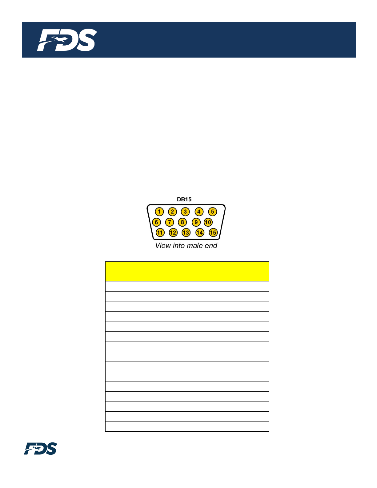
Power/Video
Pin out for P1 (High Density DB-15 Receptacle)
There is one High Density DB-15 on the rear of the display, which connects
Power, Composite Video #1, Composite Video #2 and VGA connections.
Part Numbers for DB-15 connectors, manufactured by Tyco or Amp.
High density, D-sub, 15 contact plug (male) P/N 74836-1
High density, D-sub, 15 contact receptacle (female) P/N 748565-1
HD15M pins P/N M39029/58-360
HD15F pins P/N M39029/57-354
Pin
Number
Description
1
28VDC Power
2
28VDC Ground
3
N/C
4
Composite Video #1 - Signal
5
Composite Video #1 - Shield
6
N/C
7
Composite Video #2 - Signal
8
Composite Video #2 - Shield
9
Red Video (RGB/VGA)
10
Green Video (RGB/VGA)
11
Blue Video (RGB/VGA)
12
Red Ground (RGB/VGA)
13
Green Ground (RGB/VGA)
14
Horizontal Sync (RGB/VGA)
15
Vertical Sync (RGB/VGA)

Document Number:
MAN –FD102CV-LP-S
Rev:
A
Revision Date:
11/17/2010
Page 9 of 15
©2015 Flight Display Systems.
All Rights Reserved.
TECHNICAL SUPPORT
470-239-7421 or FlightDisplay.com
Operation Instructions
The FD102CV-LP-S is continuously on but can be de-energized by removing power from
the entertainment system. No pilot or aircrew action is necessary during flight or ground
operation.
Passengers can change the video output from the FD102CV-LP-S using the video source
select switch on the included IR remote.
The IR LED, located on the top of the monitor, must be visible to the remote for wireless
operation.
Button Controls
The button controls are located on the bottom of the monitor on the right side.
Button functions are described in the table below.
BUTTON
DESCRIPTION
1
DOWN
Moves to the next selection in the menu.
2
UP
Moves to the previous selection in the menu.
3
MENU
Opens the MENU.
4
SOURCE
Switches between sources coming into the display.
5
POWER
Toggles the power ON or OFF. Also, wakes the display up from
SLEEP mode.

Document Number:
MAN –FD102CV-LP-S
Rev:
A
Revision Date:
11/17/2010
Page 10 of 15
©2015 Flight Display Systems.
All Rights Reserved.
TECHNICAL SUPPORT
470-239-7421 or FlightDisplay.com
Remote Control Buttons
The IR LED, located on the top of the monitor, must be visible to the remote for wireless
operation. Refer to button controls on previous page for remote control button functions.

Document Number:
MAN –FD102CV-LP-S
Rev:
A
Revision Date:
11/17/2010
Page 11 of 15
©2015 Flight Display Systems.
All Rights Reserved.
TECHNICAL SUPPORT
470-239-7421 or FlightDisplay.com
Troubleshooting
VGA Shadowing
Most of shadowing problems are due to shielding on the wire. Locate the point where all of
the shields are connected. Cut away the shields, one at a time, while viewing the display
on the screen to observe which shield is causing the noise. Cutting away one shield at a
time will allow you to focus and isolate the video noise issue.
Twisted pair wiring is prone to video noise. ECS VGA Wire
(Detailed under “Video Wiring Suggestions”) is recommended.
Snow or Sweeping Lines
Lines that slowly sweep up and down are a result of AC noise. This AC noise can be
generated by a power cart on the aircraft. Take the power cart off of the aircraft. Be careful
of inverter wiring, which can also cause noise. Stand off the wires, if necessary.
If snow or sweeping lines persist, it is possible that the ground is at an incorrect point in
the aircraft. Try moving the ground to another location.
No power to Monitor, or No video Input
• Verify correct wiring. Check the base receptacle connectors for possibly damaged pins.
• Check that the video source is:
1. Powered on,
2. In Play mode, and
3. Displaying video.
Color Distortion
• Adjust brightness and contrast settings using the buttons on the monitor.
Remote Control Inoperable
• Confirm that the infrared eye on the LCD screen is visible.
• Replace battery in remote control.

Document Number:
MAN –FD102CV-LP-S
Rev:
A
Revision Date:
11/17/2010
Page 12 of 15
©2015 Flight Display Systems.
All Rights Reserved.
TECHNICAL SUPPORT
470-239-7421 or FlightDisplay.com
Technical Support
Should you have any questions concerning this product or other Flight Display Systems
products, please contact our Product Support representatives at (470) 239-7421.
Flight Display Systems
6435 Shiloh Road
Alpharetta, GA 30005
Phone: 470-239-7400
Fax: 678-867-6742
Email: [email protected]
For further product information, technical data and sample wiring diagrams, please click on
the Dealers section of our web site at www.FlightDisplay.com
Instructions for Continued Airworthiness
The FD102CV-LP-S is designed not to require regular general maintenance.

Document Number:
MAN –FD102CV-LP-S
Rev:
A
Revision Date:
11/17/2010
Page 13 of 15
©2015 Flight Display Systems.
All Rights Reserved.
TECHNICAL SUPPORT
470-239-7421 or FlightDisplay.com
Limited Warranty
All Flight Display Systems (FDS) products are warranted to be free from material or manufacturing defects for a
period of 24 months from the date of shipment for General Aviation customers or 12 months from the date of
shipment for Government/Special Mission customers. Any material or repair workmanship for in warranty repair
service will be specifically warranted for 90 days or the remainder of the original warranty period, whichever is
longer. If the original warranty period has expired, the 90 day repair warranty is limited to the material and
workmanship specific to the repair activity completed.
The following conditions are exclusions to warranty coverage:
1. Labor costs associated with installation, removal or reinstallation of any product.
2. Damage to or malfunction caused by any unauthorized alteration made to the product.
3. Resolving signal quality issues caused by externally generated noise introduced by aircraft electrical
systems or other components connected to any FDS product.
4. Any malfunction caused by improper installation or connection to aircraft wiring, industry standard cabin
management/ inflight entertainment systems, or third party commercial equipment not specifically identified
as compatible with FDS products.
5. Any malfunction caused by installation that does not conform to precautions associated with operating
environments listed in the operating manual or consistent with industry best practices such as; high
temperature, adequate ventilation, high humidity, high dust, or power surges.
6. Cosmetic damage or damage to internal components caused by installation or removal, failure to follow
installation or operating instructions, or any neglect or misuse of the product.
7. Any product that is returned for service with a broken tamper evident seal, indicating tampering or improper
handling of the product by an unauthorized person. Violation of product tamper evident seals or
modification of factory installed serial and PMA labels voids any warranty, either expressed or implied.
The FDS technical support team is available to provide distance troubleshooting support during business hours
(8:00am to 5:00pm EST) Monday through Friday at (470) 239-7421.
Many repair requests can be resolved through distance support and may not require return of merchandise to the
factory. If a product must be returned to the factory for repair, an RMA number will be issued as directed by the
technical support team and communicated by the repair coordinator.
Upon request by the customer, FDS may send a service technician onsite to repair any non-PMA products. The
travel expenses incurred to include transportation, lodging and meals along with the technician’s hourly rate shall
be payable by the customer in accordance with FDS’ applicable rates and procedures.
Flight Display Systems will, upon receipt of returned merchandise, remanufacture or replace the unit at our
discretion and return the product by Ground Return Shipping. Express return shipment will be the responsibility of
the sender.
This warranty is not transferable.
Any implied warranties expire at the express limited warranty expiration date. FDS shall not be held liable for any
indirect, special, punitive, incidental or consequential damages.
Some states do not allow limitation on the length of an implied warranty. In such states, the exclusions or
limitations of this limited warranty may not apply.

Document Number:
MAN –FD102CV-LP-S
Rev:
A
Revision Date:
11/17/2010
Page 14 of 15
©2015 Flight Display Systems.
All Rights Reserved.
TECHNICAL SUPPORT
470-239-7421 or FlightDisplay.com
Installation Drawing

Document Number:
MAN –FD102CV-LP-S
Rev:
A
Revision Date:
11/17/2010
Page 15 of 15
©2015 Flight Display Systems.
All Rights Reserved.
TECHNICAL SUPPORT
470-239-7421 or FlightDisplay.com
Log of Revisions
Rev
Date
Page
Description
A
11/17/2010
Initial Release
Other manuals for FD102CV-LP-S
1
Table of contents


