FEDERAL PACIFIC PMDF Series User guide

601 Old Airport Road • Bristol, VA 24201 Phone (276) 669-4084 • FAX (276) 669-1869 • www.federalpacific.com • ISO9001:2015
SECTION IB-2D-700
INSTALLATION & OPERATION INSTRUCTIONS
PMDF PAD-MOUNTED SWITCHGEAR
NOVEMBER 2017 VER. 2.1
PAGE 1
TYPE PMDF
INSTRUCTIONS FOR INSTALLATION AND OPERATION
15kV • 25kV • 35kV
QUALIFIED PERSONS ..........................................1
SAFETY ......................................................2
Safety Information ..........................................2
Following Safety Instructions .................................2
Safety Precaution ...........................................2
INTRODUCTION ...............................................3
Receiving ..................................................3
Handling ...................................................3
Storage ....................................................3
GENERAL DESCRIPTION .......................................3
SECURITY FEATURES ..........................................3
INSTALLATION ................................................4
Placement of Unit ...........................................4
Customer Cable Connections .................................4
BUSHING WELLS AND BUSHINGS ..............................5
Bushing Wells ..............................................5
Bushings ...................................................6
REMOVAL OF LOADBREAK ELBOWS .............................6
INSTALLATION OF METERING TRANSFORMERS ..................7
TYPICAL DIMENSIONS.........................................8
DOOR SYSTEM................................................9
Door-Latch Features .........................................9
MAINTENANCE ..............................................10
OPTIONAL FEATURES .........................................10
Figure 1. External views of PMDF Pad-Mounted Switchgear with optional
KWH meter mounted in an isolated low-voltage compartment attached to unit.
Federal Pacific PMDF models meet applicable industry standards, which are
ANSI 386 and IEEE C57.12.28.
© 2014 Electro-Mechanical Corporation
Qualified Persons
The equipment covered by this publication must be selected for a spe-
cific application and it must be operated and maintained by Qualified
Persons who are thoroughly trained and knowledgeable in the instal-
lation, operation, and maintenance of underground power distribution
equipment along with the associated hazards that may be involved. This
publication is written only for such qualified persons and is not intended
to be a substitute for adequate training and experience in safety proce-
dures for this type of equipment. Proper installation is the responsibility
of the operating and construction personnel and the utility performing
and authorizing the work. Completion of these instructions implies no
further warranty by the manufacturer.
A Qualified Person is defined in the National Electrical Code (NEC/
NFPA-70) as:
One who has skills and knowledge related to the construction and op-
eration of the electrical equipment and installations and has received
safety training to recognize and avoid the hazards involved.
The specific electrical safety training requirements to be considered a
qualified person are detailed in NFPA-70E, Article 110.1(D), Employee
Training. Some of the requirements from the 2012 edition are shown
below. For the specific detailed training requirements for a Qualified
Person make certain to refer to the most recent applicable edition.
These training requirements would include, but are not limited, to the
following key points:
• The skills and techniques necessary to distinguish exposed energized
parts from other parts of electrical equipment.
• The skills and techniques necessary to determine the proper approach
distances corresponding to the voltages to which the qualified person
will be exposed.
• The proper use of the special precautionary techniques, personal pro-
tectiveequipment,insulatingandshieldingmaterials, and insulatedtools
for working on or near exposed energized parts of electrical equipment.
• Tasks performed less often than once per year have additional training
requirements.
These instructions are intended only for such qualified persons. They
are not intended to be a substitute for adequate training and experience
in safety procedures for this type of equipment. Additionally, the recom-
mendations in this instruction bulletin are not intended to supersede or
to take the place of established utility safety guidelines and established
practices. If there is any question, consult with your foreman or supervi-
sor, as appropriate.
Please refer to OSHA 29 CFR 1910.399 and NFPA 70E Articles 100 and 110.
WARNING

601 Old Airport Road • Bristol, VA 24201 Phone (276) 669-4084 • FAX (276) 669-1869 • www.federalpacific.com • ISO9001:2015
SECTION IB-2D-700
INSTALLATION & OPERATION INSTRUCTIONS
PMDF PAD-MOUNTED SWITCHGEAR
NOVEMBER 2017 VER. 2.1
PAGE 2
SAFETY INFORMATION
Understanding Safety-Alert Messages
There are several types of safety-alert messages which may
appear throughout this instruction bulletin as well as on labels
attached to the pad-mounted switchgear. Familiarize yourself
with these types of messages and the importance of the various
signal words, as explained below.
If you do not understand any portion of this instruction bulletin
and need assistance, contact the Switchgear Division of Federal
Pacific at 276-669-4084.
Replacement Instructions & Labels
If you need additional copies of this instruction bulletin, contact
Federal Pacific at 276-669-4084.
It is important that any missing, damaged, or faded labels on the
equipment be replaced immediately. Replacement labels are
available by contacting Federal Pacific.
SAFETY PRECAUTION
FOLLOWING SAFETY INSTRUCTIONS
NOTICE
Thoroughly and carefully read this instruction
bulletin before installation of the pad-mounted
switchgear, before switching with elbows or
installingoraccessingthemeteringtransformers
in this equipment, and before performing any
maintenance on the equipment.
......
DANGER
Federal Pacific Fuse Mountings in conjunction with appropri-
ate fuses are designed to protect equipment and to disconnect
faulted equipment from the system. The fuses cannot protect
personnel from injury or electrocution if contact is made with
energized circuits or hardware.
NOTICE
NOTICE is used to address practices not related to physical
injury.
SAFETY
INSTRUCTIONS
SafetyInstructions (orequivalent)signs indicatespecific safety-
related instructions or procedures.
DANGERindicates a hazardoussituationwhich, if notavoided,
will result in death or serious injury.
DANGER
WARNING
WARNINGindicatesahazardoussituationwhich, ifnotavoided,
could result in death or serous injury.
CAUTION
CAUTIONindicatesa hazardoussituationwhich,ifnot avoided,
could result in minor or moderate injury.

601 Old Airport Road • Bristol, VA 24201 Phone (276) 669-4084 • FAX (276) 669-1869 • www.federalpacific.com • ISO9001:2015
SECTION IB-2D-700
INSTALLATION & OPERATION INSTRUCTIONS
PMDF PAD-MOUNTED SWITCHGEAR
NOVEMBER 2017 VER. 2.1
PAGE 3
Introduction
PMDF pad-mounted switchgear is designed to provide depend-
able on-the-line service and to make installation, operation
and maintenance as simple as possible. Federal Pacific PMDF
models meet applicable industry standards, which are ANSI 386
and IEEE C57.12.28.
High quality materials and careful workmanship have been com-
binedtoprovidethebestswitchgearavailable. Theswitchgearhas
been thoroughly inspected and adjusted at the factory. However,
successful operation depends on proper installation and care.
This manual has been written to assist you in obtaining long and
economical service from your switchgear.
Readthismanualbeforeinstallingandoperatingyourswitchgear.
Receiving
Upon receipt of the switchgear, check each item received for
shipping damage. Each item should be checked against the ship-
ping manifest to assure that the proper number of items were
received. Should any shortage or damage exist, note it on the
shipping papers. A claim should be filed at once with the carrier
and the Federal Pacific agent or sales office should be notified.
The carrier is responsible for all damage occurring during tran-
sit. Receiving personnel must note all damage to equipment on
shipping papers so that claims can be processed.
Handling
Removable lifting plates are provided to allow the use of hooks to
lift the complete enclosure. The lifting device should be arranged
to evenly distribute the lifting force between the lifting plates.
Do not lift at an angle less than 60° from the horizontal. See
Figure 2. A spreader bar may be required to maintain the proper
minimum angles. Failure to comply with this requirement may
result in damage to the equipment.
The switchgear is securely mounted to a sturdy shipping pallet
with provisions for forklift use. The use of a forklift truck is not
recommended, but if this method is used the forks must extend
completely through the skid to avoid damaging the equipment.
Storage
The switchgear as received may be wrapped in a protective
plastic film, which must be removed for storage.
To avoid damage to the enclosure finish, the protective film
must be removed for outdoor storage of unit.
Export or special packing is available as an option based on
customer’s requirements and special conditions. Separate in-
structions are available for these situations.
Figure 2. Lifting Method
General Description
PMDF dead-front pad-mounted
switchgear consists of one or more
single-pole 200 ampere bushing
wells to accommodate 200 ampere
loadbreak (or non-loadbreak) in-
serts and elbows. Alternately, the
unit may be optionally equipped
with
600 ampere bushings to ac-
commodate 600 ampere elbow
connectors. When used with 200
ampere bushing wells and load-
break inserts and elbows, and
other protectivedevices, thePMDF
switchgear provides a secure and
efficient means of single-pole
switching with elbows on the in-
coming lines.
In addition, the unit may be furnished with metering transformers
(voltage transformers and current transformers), or provisions
only for metering transformers, and with optional meter socket
(mounted on the enclosure or in a low-voltage compartment)
and associated wiring. When the unit is provided with “Mount-
ing Provisions only for Metering Transformers, the customer is
responsible for providing, installing, wiring, and connecting all
metering transformer and associated secondary components.
Security Features
PMDF pad-mounted switchgear meets the security require-
ments in IEEE C57.12.28 and incorporates a number of security
features to minimize hazards to operating personnel.
1. Rugged 11-gauge steel, using all welded construction of the
enclosure, with a bolted roof, and hinged and bolted doors
assures a tamper-resistant design.
2. Padlockable doors with security bolts provide customer-
controlled access.
3. 200 ampere bushing wells of cycloaliphatic epoxy and with
removable studs.
NOTICE
NOTICE
4. Hazard-alert signs and labels, both external and internal,
indicate potential hazards to personnel.
5. Full-width fiberglass barriers (or optional clear polycarbonate
barriers) behind doors on fuse compartment.
6. Wind brace to secure enclosure door open and a cable-
connected clip to secure inner barriers open.
WARNING
Before energizing the switchgear, remove all yellow and red
shipping caps on bushings and bushing wells, and replace
them with a suitable system of insulated separable connectors
(elbows), insulating protective covers, or plugs, as appropriate.
Failure to replace the shipping caps may result in flashover,
equipment damage, serious personal injury, or death.
CAUTION
601 Old Airport Road • Bristol, VA 24201 Phone (276) 669-4084 • FAX (276) 669-1869 • www.federalpacific.com • ISO9001:2015
SECTION IB-2D-700
INSTALLATION & OPERATION INSTRUCTIONS
PMDF PAD-MOUNTED SWITCHGEAR
NOVEMBER 2017 VER. 2.1
PAGE 4
Customer Cable Connections
1. Make up the primary cable connections per user’s standard
URDoperatingprocedures,cable manufacturer instructions, and
elbow terminator manufacturer instructions.
Installation
Each unit is shipped with this instruction bulletin which is located
inside one of the compartment doors. These instructions should
be reviewed prior to placing unit on pad.
Placement of Unit
Remove unit from shipping pallet per handling procedures on
Page 3 (see Figure 2). When unit has been correctly oriented and
placed on pad (see Figure 3), verify that unit is level and shim if
necessary between unit base and pad. Secure unit to pad using
four (4) tie-down clips as furnished (see Figures 3, 4 and 5). Check
compartment door operation for any binding due to enclosure
distortion and re-shim if necessary. A recessed grouting should
then be applied between unit base and pad to prevent entry of
foreign objects, vegetation, insects, animals, and moisture.
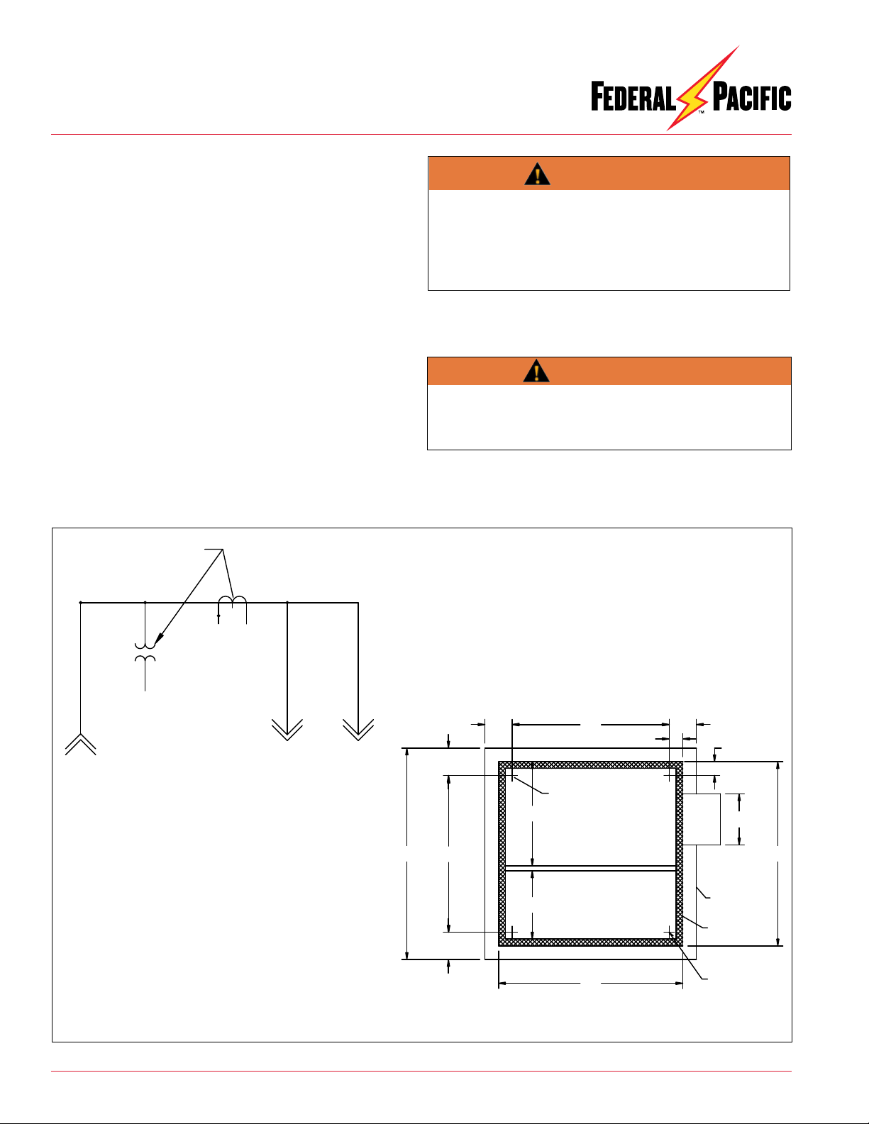
Figure 3. Typical pad layout and associated circuit diagram for one particular PMDF design. DO NOT USE FOR CONSTRUCTION PURPOSES.
2. Connect the concentric neutral wires to the enclosure ground
pads inside the enclosure to facilitate ground system conforming
to user’s grounding procedures.
The maximum momentary rating of the switchgear must
be considered when selecting cable size for connecting
switchgear to system ground. Refer to unit rating sheet on
inside of doors.
3. Install fault indicators, if applicable in accordance with the
manufacturer’s instructions.
ONE LINE DIAGRAM
LINE LOAD LOAD
"CT" AND "PT"
8
46
8
54
5462 45 3/4
30 1/2
20
8
8
15
4
4
RECOMMENDED PAD LAYOUT
COMPARTMENT
METERING
SEE CORNER DETAIL
ELBOW
COMPARTMENT
ANCHOR BOLT
LOCATIONS
CUSTOMERS
EQUIPMENT
BASE
PAD
WARNING
WARNING
Before energizing the switchgear, remove all yellow and red
shipping caps on bushings and bushing wells, and replace
them with a suitable system of insulated separable connectors
(elbows), insulating protective covers, or plugs, as appropriate.
Failure to replace the shipping caps may result in flashover,
equipment damage, serious personal injury, or death.
601 Old Airport Road • Bristol, VA 24201 Phone (276) 669-4084 • FAX (276) 669-1869 • www.federalpacific.com • ISO9001:2015
SECTION IB-2D-700
INSTALLATION & OPERATION INSTRUCTIONS
PMDF PAD-MOUNTED SWITCHGEAR
NOVEMBER 2017 VER. 2.1
PAGE 5
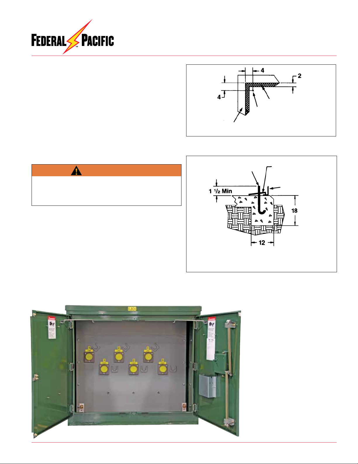
Figure 5. Bolting Units to Pad
Cabinet
5/8-11 Anchor
Bolts (by others) 4 Tie Down
Plates Provided With
Unit
Recommended
Pad Section
Figure 4. Typical Anchor Bolt Location
Corner Detail
Anchor Bolt
Enclosure Flange
Customers
Box Pad
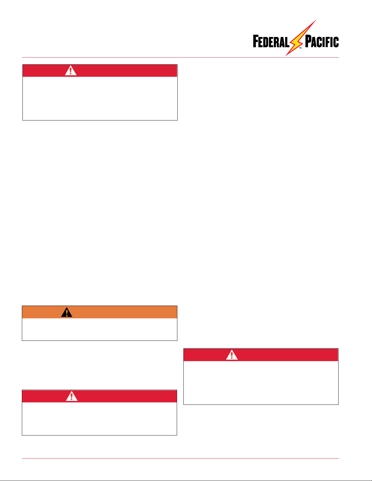
Figure 6. View of PMDF elbow-compartment
side with doors open to show customer selected
bushing wells (pictured) or, if specified optional
600 ampere bushings. The 200 ampere bushing
wells accommodate loadbreak inserts and
elbow connectors. Dust covers (yellow discs)
must be removed from all unused positions and
replaced with protective insulating bushing-
well plugs (or insulating bushing covers when
furnished with 600 ampere bushings, which
have red dust covers).
Bushing Wells and Bushings
Federal Pacific PMDF Pad-Mounted Switchgear is furnished
with a choice of either 200 ampere bushing wells or 600 ampere
bushings on the line side or load side. The bushing wells and
bushings meet ANSI 386 standard requirements.
Bushing Wells
The 200 ampere bushing wells accommodate 200 ampere elbow
(separableinsulated)loadbreakconnectors and accessories. The
units are shipped with a yellow dust cover over each bushing well
to preventcontamination. Dust covers are NOT capable of
provid-
ing any electricalinsulationat medium voltage levels.Therefore,
if an elbow is not to be connected to a bushing well, prior to
energization the dust cover MUST be removed and replaced
with an insulating protective bushing-well plug. See Figure 6.
Install load-break inserts following the insert manufacturer’s
instructions supplied therewith. Terminate cables and install 200
ampereloadbreakelbowsandaccessoriesfollowinginstructions
provided by the cable manufacturer and the elbow manufacturer.
The 200 ampere elbows are a loadbreak device and, if standard
system operating practices and conditions permit, may be re-
moved when the equipment is energized, providing single-pole
loadbreak live switching is performed using insulated shotgun
clamp sticks. Before performing any live-switching with elbows,
install insulating feed-through standoff bushings on the parking
stand adjacent to the loadbreak elbow to be switched.
WARNING
For all un-terminated phase positions, failure to remove dust
covers and replace with a protective insulating bushing-well
plug prior to energization may result in equipment damage,
personal injury or death.
601 Old Airport Road • Bristol, VA 24201 Phone (276) 669-4084 • FAX (276) 669-1869 • www.federalpacific.com • ISO9001:2015
SECTION IB-2D-700
INSTALLATION & OPERATION INSTRUCTIONS
PMDF PAD-MOUNTED SWITCHGEAR
NOVEMBER 2017 VER. 2.1
PAGE 6
Terminate cables and install 600 ampere elbows and accessories
following instructions provided by the cable manufacturer and
the elbow manufacturer. The 600 ampere elbows are a dead-
break device and must NOT be removed when the equipment
is energized.
Always follow user’s and manufacturer’s standard operating
procedureswhen installing, maintainingor removing 200 ampere
loadbreak elbow connectors and accessories. Such procedures
should always include:
1. Verifying the correct circuit is being maneuvered,
2. Installing portable feed-through standoff bushings on the
parkingstandadjacenttotheloadbreakelbow tobe switched,
3. Recognizing that the unit may be subject to back feed and
taking necessary precautions to isolate the equipment from
such possibility before maneuvering 200 amp elbows when
dead-break procedures are to be followed,
4. Testing for voltage, and
5. Grounding the circuits before any other work is attempted.
Bushings
The 600 ampere bushings accommodate 600 ampere elbow
(separable insulated) connectors and accessories. The units
are shipped with a red dust cover over each bushing to prevent
contamination. Dust covers are NOT capable of providing any
electrical insulation at medium voltage levels. Therefore, if an
elbow is not to be connected to a bushing, prior to energization
the dust cover MUST be removed and replaced with an insulating
protective bushing cover.
Always follow user’s and manufacturer’s standard operating
procedureswheninstalling,maintainingorremoving600 ampere
elbow connectors. Such procedures should always include:
1. Opening adjacent load-interrupting devices to completely de-
energize the unit,
2. Recognizing that the unit may be subject to back feed and tak-
ing necessary precautions to isolate the equipment from such
possibility before maneuvering 600 amp elbows,
3. Testing for voltage to verify circuit is de-energized before
maneuvering 600 amp elbows, and
4. Grounding the circuits before any other work is attempted.
Removal of Load-Break Elbows
1. Remove the padlock and fully loosen the penta-head bolt. Pull
and lower the door handle cover to open the active elbow-
compartmentdoorandsecurewiththewindbrace. SeeFigures
7 through 14.
2. Loosenthetwo pentaheadboltsthatsecurethepassiveelbow
compartment door and secure it open using the windbrace.
3. System operating practices may allow loadbreak elbows to
be switched while the associated cable is energized. Follow
loadbreak elbow manufacturer’s procedures for proper tech-
nique whenlive switchingisto beperformedusing theelbows.
If live switching is not permitted with elbows, appropriately
rated voltage testers should be used to verify that the circuit
is completely de-energized.
4. Using the shotgun clamp stick, install and secure the feed-
through standoff bushing on the parking stand.
5. If live switching of elbows is not permitted for operating
circumstances of the system, test the elbow to be moved for
voltage. After verifying that voltage is not present, or if live
switching is permitted, use the shotgun clamp stick to remove
the elbow connector from the appropriate bushing well, fol-
lowing standard system operating procedures and the elbow
manufacturer’s instructions. Move the elbow connector onto
a standard feed-thru standoff bushing that is placed in the
parking stand.
WARNING
Failure to remove dust covers and replace with a protective
insulating bushing cover prior to energization may result in
equipment damage, personal injury or death.
DANGER
Do not attempt to remove 600 ampere elbows (separable
insulated) connectors when the equipment is energized. Any
attempt to remove 600 ampere elbows while the equipment
is energized will result in equipment damage, personal injury
or death.
DANGER
When removing energized 200 ampere elbows (separable
insulated) connectors, do not allow the elbow probe to
touch any grounded surface. Before working on any cables
or circuits, test for voltage and ground the circuit. Failure to
follow proper procedures while the equipment is energized
will result in equipment damage, personal injury or death.

601 Old Airport Road • Bristol, VA 24201 Phone (276) 669-4084 • FAX (276) 669-1869 • www.federalpacific.com • ISO9001:2015
SECTION IB-2D-700
INSTALLATION & OPERATION INSTRUCTIONS
PMDF PAD-MOUNTED SWITCHGEAR
NOVEMBER 2017 VER. 2.1
PAGE 7
6. Install an insulating protective cover on the exposed 200
amp bushing-well insert following grounding-elbow manu-
facturer’sinstructions.Connecttheground-clampconnector
of the grounding elbows to the enclosure ground rod.
Before installing grounding elbows, test for voltage. Failure
to properly test for voltage to establish that the circuit is de-
energized before installing grounding elbow may result in
equipment damage, personal injury or death.
7. If appropriate for operating circumstances of the system,
test the remaining feed-through standoff bushings for volt-
age and, after confirming that voltage is not present, then
install a grounding elbow on the remaining bushing.
8. Repeattheabove proceduresfor each200 ampere loadbreak
elbow that is to be moved.
9. Aftercompletingthework tobeperformed,the groundelbows
are to be removed. First, remove the grounding elbow from
the feed-thru bushing. Then, remove the ground connector
from the ground rod.
10. If applicable, remove the insulating protective cover from
the bushing-well insert.
11. Following elbow manufacturer’s proper procedure for posi-
tioning, removal and closing circuit using elbows, move the
elbow connector from the feed-through standoff bushing
and secure it onto the 200 ampere bushing-well insert.
12. Remove the feed-through standoff bushing.
13. Remove and store the windbrace.
14. Close and secure the passive door by fully tightening both
the top and bottom penta-head bolts.
15. Close and padlock the main doors before leaving the gear.
Installation of Metering Transformers
1. Remove the padlock and fully loosen the penta-head bolt. Pull
and lower the door handle cover to open the active elbow-
compartmentdoorandsecurewiththewindbrace. SeeFigures
7 through 14.
2. Loosenthetwopentaheadboltsthatsecure thepassiveelbow
compartment door and secure it open using the windbrace.
3. Loosen the penta-head bolts on each inner barrier and secure
them open using the pin proved on the door inserted into the
clip on the top edge of the barrier.
4. Installthevoltagetransformers(alsoknownaspotentialtrans-
formers or PTs) and current transformers (CTs) in accordance
with the manufacturer’s instructions and the user’s standard
operatingpractice. Makecertainthatthecurrenttransformers
are installed and oriented in the proper polarity.
5. The voltage transformer incoming connections must be in-
stalled on the line (or source) side of the current transformer
connections.
6. Make the connections for the voltage transformers with ap-
propriately sized copper bus or insulated copper cable.
7. Make the connections for the wound (or bar) type current
transformerswiththeappropriatelysizedcopperbusorcopper
cable.
8. Install and wire a shorting-type terminal block on the sec-
ondary side of the current transformers in accordance with
applicable manufacturer’s instructions and user’s standard
practice instructions.
9. Install and wire a terminal block on the secondary side of
the voltage transformer in accordance with the applicable
manufacturer’s instructions and the user’s standard practice
instructions.
10. Make appropriately protected secondary connections from
the voltage transformer’s and current transformers to the
kilowatt-hour meter in accordance with the applicable
manufacturer’sinstructionsand theuser’sstandard practice
instructions.
Figure 8. Open door view of metering transformers with
fiberglass inner barriers secured open.
Figure 7. Open door view of PMDF with inner
barriers bolted in place.
WARNING

601 Old Airport Road • Bristol, VA 24201 Phone (276) 669-4084 • FAX (276) 669-1869 • www.federalpacific.com • ISO9001:2015
SECTION IB-2D-700
INSTALLATION & OPERATION INSTRUCTIONS
PMDF PAD-MOUNTED SWITCHGEAR
NOVEMBER 2017 VER. 2.1
PAGE 8
Catalog
Number
Volt
Nom.
kV
BIL
Dimensions - Inches*
A B C D E F G H J K L M N P R
PMDF-315-R6-200 15 95 54 54 51 22 28 14 14 7 NA NA 22 62 62 46 46
PMDF-315-L9-200 15 95 54 54 51 22 28 14 14 7 5 8-5/8 22 62 62 46 46
PMDF-325-R6-200 25 125 66 66 51 24-1/2 30-1/2 17-1/2 16 8-1/2 NA NA 24 74 74 58 58
PMDF-325-L9-200 25 125 66 66 51 24-1/2 30-1/2 17-1/2 16 8-1/2 6 8-3/8 24 74 74 58 58
PMDF-335-R6-200 35 150 76 66 53 24-1/2 33 22-1/2
18-5/16
12-9/16
5-5/8 8-1/2 24 74 84 68 58
34.5 kV designed to customer specifications.
Typical Dimensions*
*Do not use these dimensions for construction purposes.

601 Old Airport Road • Bristol, VA 24201 Phone (276) 669-4084 • FAX (276) 669-1869 • www.federalpacific.com • ISO9001:2015
SECTION IB-2D-700
INSTALLATION & OPERATION INSTRUCTIONS
PMDF PAD-MOUNTED SWITCHGEAR
NOVEMBER 2017 VER. 2.1
PAGE 9
Door System
The door latching feature furnished on the main doors provides
ease in opening and closing of the doors.
Door-Latch Features
Features of the door-latch system are:
• Three-point latching of doors. See Figure 12.
• After unlatching on opening, the door is secured open with
a windbrace. Hinged inner barriers are secured open with
a cable-connected pin on the door and inserted into a clip
on the top edge of the barrier. See Figure 12. For closing, the
door is manually latched, bolted closed and padlocked.
• Unlatching is only accomplished by first rotating (in counter-
clockwise direction) the captive penta-head (or hex-head)
bolt through several revolutions and then lowering the door
handle. See Figures 8 through 10.
Figure 13. Padlock cannot be inserted until
penta-head bolt is fully tightened.
Figure 14. Always close, latch and padlock
the enclosure door before leaving the unit or
when working on the opposite side.
Figure 10. Door handle cover is secured
closed by a penta-head (or hex-head) bolt.
Turn socket counter-clockwise to loosen
bolt.
Figure 9. Door handle is stainless steel. Figure 11. With penta-head bolt fully
loosened, handle can be pivoted down to
unlatch the door.
Figure 12. Three-point door latch
mechanism. Enclosure door is
secured open by windbrace. Inner
barrier is secured open by a pin on
the door inserted into a clip on the
barrier.
• The door padlocking provision prevents unlatching the door-
latch cover until the padlock has been removed. Padlocking
also secures the door to the cabinet enclosure. See Figures
13 and 14.
• The protective door-latch cover is stainless steel. Also, ac-
cess to the penta-head bolt is only possible after the padlock
has been removed.
• A closed, latched and padlocked door can successfully
withstand a "pull" greater than 600 pounds at any point on
the door.
601 Old Airport Road • Bristol, VA 24201 Phone (276) 669-4084 • FAX (276) 669-1869 • www.federalpacific.com • ISO9001:2015
SECTION IB-2D-700
INSTALLATION & OPERATION INSTRUCTIONS
PMDF PAD-MOUNTED SWITCHGEAR
NOVEMBER 2017 VER. 2.1
PAGE 10
Maintenance
FederalPacificswitchgeardoesnotrequireroutine mechanical or
electrical maintenance. However, the following are some recom-
mendations for enhancing continued service of the equipment.
1. Yearly mechanical exercising of the loadbreak elbows is
recommended.
The switchgear must be completely de-energized from all
sources before any attempt is made to enter the metering
transformer compartment of the switchgear.
2. Check for cleanliness generally, but particularly for accumula-
tion of any foreign material on insulators, barriers and metering
transformers.
Barriersand insulatorscan be cleanedwith anon-alcoholbased
cleaner that does not leave any residue when dry. Residue
must be removed.
Optional Features
Standard options can be supplied that best serve the customer's
needs and operating practices. These are listed below with the
applicable catalog number suffix.
Base Spacer-Non-compartmented or compartmented suffix
beginning with letter “-A” — followed by a number, or “-AS”
followed by a number when of stainless steel.
Finish Color and Special Cabinet Material
Fault Indicators
Copper Bus (-C)
Strip Heaters
Stainless Steel (-F4)
600 Ampere Bushings in lieu of 200 ampere bushing wells
(-600)
NOTICE
WARNING

601 Old Airport Road • Bristol, VA 24201 Phone (276) 669-4084 • FAX (276) 669-1869 • www.federalpacific.com • ISO9001:2015
SECTION IB-2D-700
INSTALLATION & OPERATION INSTRUCTIONS
PMDF PAD-MOUNTED SWITCHGEAR
NOVEMBER 2017 VER. 2.1
PAGE 11
This Page Intentionally Left Blank

601 Old Airport Road • Bristol, VA 24201 Phone (276) 669-4084 • FAX (276) 669-1869 • www.federalpacific.com • ISO9001:2015
SECTION IB-2D-700
INSTALLATION & OPERATION INSTRUCTIONS
PMDF PAD-MOUNTED SWITCHGEAR
NOVEMBER 2017 VER. 2.1
PAGE 12
This Page Intentionally Left Blank
Every effort is made to ensure that customers receive an up-to-date instruction manual on the use of Federal Pacific
products; however, from time to time, modifications to our products may without notice make the information contained
herein subject to alteration.
© 2014 Electro-Mechanical Corporation
This manual suits for next models
5
Table of contents
Popular Industrial Electrical manuals by other brands

Murata
Murata GRT155C81A105ME01 Series Reference sheet

Murata
Murata GQM22M5C2H220GB01 Series Reference sheet

Eaton
Eaton Power Defense NZM-XBZ225 Instruction leaflet

Eaton
Eaton MSFA-PI Series Instruction leaflet

ION Optix
ION Optix C-Pace EP Manual for installation

Eaton
Eaton Cutler-Hammer Ampgard SC9000 instructions


Biometra
Biometra TGRADIENT 48 manual

Murata
Murata GRM0225C1E5R2BA03 Series Reference sheet

Murata
Murata GRM1557U1A472JA01 Series Reference sheet

Murata
Murata GRM1885C2A4R0CA01 Series Reference sheet

Siemens
Siemens SIRIUS 3RA132.-8XB30 operating instructions

Crossbow Technology
Crossbow Technology AHRS500GA Series Operator's manual