FEDERAL PIONEER USD User manual


INSTRUCTION
MANUAL
C
-
3
-
217
-
2
FEDERAL
PIONEER
OVERCURRENT
TRIP
UNIT
TYPE
USD
March
,
1982
TABLE
OF
CONTENTS
1
.
Introduction
1
2
.
Description
1
General
Current
Sensors
USD
Relay
Shunt
Trip
Types
of
Solid
State
Overcurrent
Trip
Units
2.1
2.2
2.3
2.4
2.5
3
.
Operation
3
3.1
General
Overcurrent
Elements
Ground
Fault
Element
The
ZSIP
Functions
Selecting
Settings
3.2
3.3
3.4
3.5
4
.
Specifications
5
Scope
Current
Sensor
Relay
Configurations
Long
Time
Element
Short
Time
Element
Instantaneous
Element
Ground
Fault
Element
Output
Trip
Pulse
Test
Signals
Relay
Impedance
(
Burden
)
Reset
Time
Performance
in
Service
4.1
4.2
4.3
1
4.4
4.5
4.6
4.7
4.8
4.9
4.10
4.11
4.12
5
.
Testing
10
5.1
Secondary
Injection
5.2
Primary
Injection
Maintenance
6
.
12
6.1
General
Troubleshooting
6.2
Courtesy of NationalSwitchgear.com


INSTRUCTION
MANUAL
C
-
3
-
217
-
2
FEDERAL
PIONEER
OVERCURRENT
TRIP
UNIT
TYPE
USD
March
,
1982
LIST
OF
FIGURES
PAGE
Functional
Block
Diagram
of
USD
Relay
Faceplate
Layout
of
USD
-
3
IR
Relay
Faceplate
Layout
of
USD
-
6
IR
Relay
Characteristics
of
the
Current
Sensors
Time
Current
Characteristics
of
USD
Relay
•
•
USD
Relay
Impedance
(
Burden
)
USD
_
Relav
Jrao
^
dance
(
Burden
)
Overcurrent
Trip
System
Connections
Remote
Indication
and
ZSIP
Connections
•
•
•
Remote
Indication
and
ZSIP
Connections
•
• •
Remote
Indication
and
ZSIP
Connections
•
•
•
Test
Connections
for
Primary
Injection
Tests
15
FIGURE
1
FIGURE
2
a
FIGURE
2
b
FIGURE
3
FIGURE
4
FIGURE
5
a
FIGURE
_
5
h
_
FIGURE
6
FIGURE
7
a
FIGURE
7
b
FIGURE
7
c
FIGURE
8
16
17
18
19
20
21
22
23
24
25
26
LIST
OF
TABLES
27
Current
Sensor
Sizes
and
Ampere
Taps
•
•
Standard
USD
Overcurrent
Relay
Models
TABLE
1
TABLE
2
28
Courtesy of NationalSwitchgear.com

INSTRUCTION
MANUAL
C
-
3
-
217
-
2
FEDERAL
PIONEER
OVERCURRENT
TRIP
UNIT
TYPE
USD
March
,
1982
INTRODUCTION
1
.
This
Instruction
Manual
contains
descriptive
operating
,
testing
and
maintenance
information
for
Federal
Pioneer
Limited
Solid
State
Overcurrent
Trip
Unit
,
Type
USD
for
protection
of
low
voltage
power
systems
.
2
.
DESCRIPTION
2.1
General
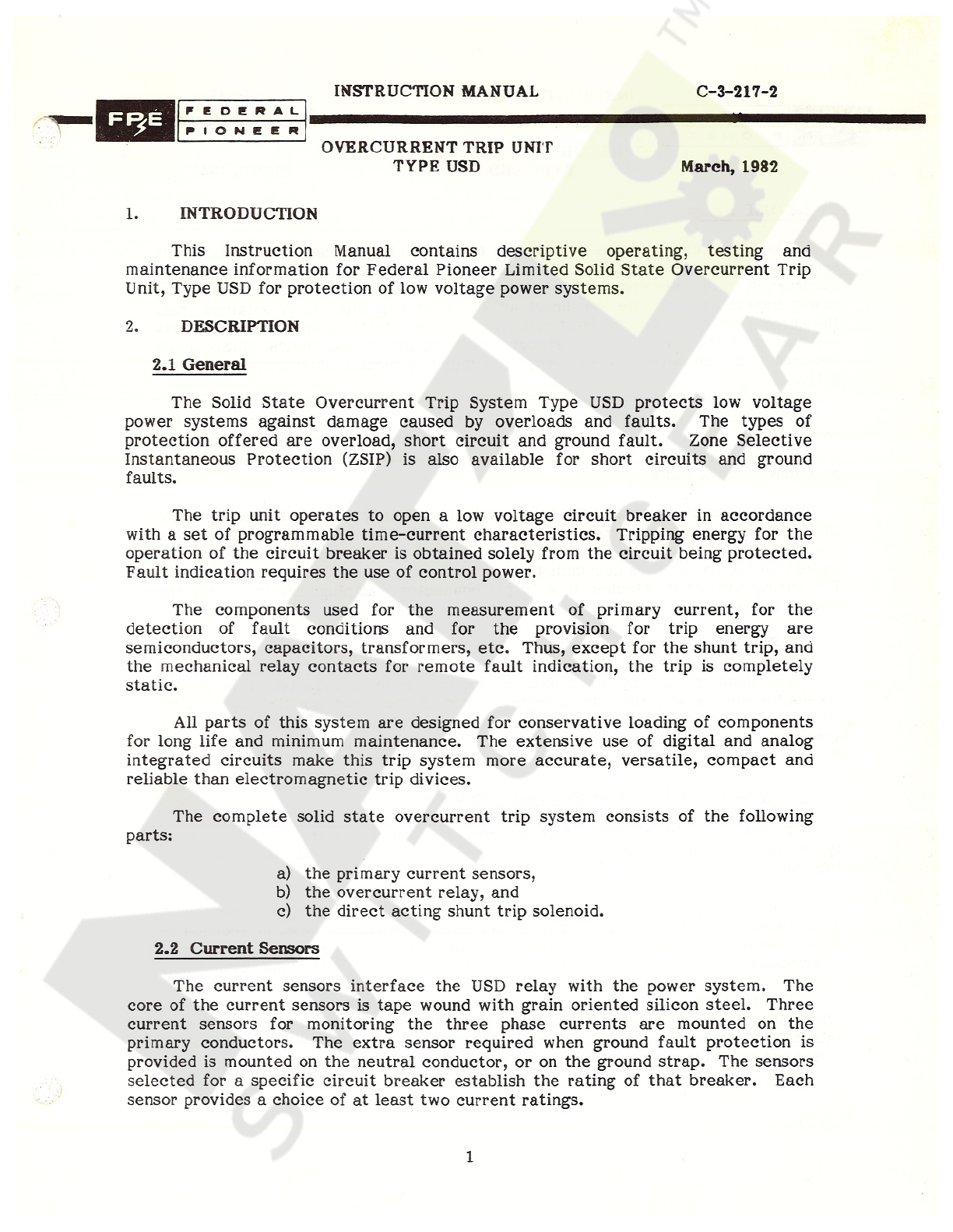
The
Solid
State
Over
current
Trip
System
Type
USD
protects
low
voltage
power
systems
against
damage
caused
by
overloads
and
faults
.
The
types
of
protection
offered
are
overload
,
short
circuit
and
ground
fault
.
Zone
Selective
Instantaneous
Protection
(
ZSIP
)
is
also
available
for
short
circuits
and
ground
faults
.
The
trip
unit
operates
to
open
a
low
voltage
circuit
breaker
in
accordance
with
a
set
of
programmable
time
-
current
characteristics
.
Tripping
energy
for
the
operation
of
the
circuit
breaker
is
obtained
solely
from
the
circuit
being
protected
.
Fault
indication
requires
the
use
of
control
power
.
The
components
used
for
the
measurement
of
primary
current
,
for
the
detection
of
fault
conditions
and
for
the
provision
for
trip
energy
are
semiconductors
,
capacitors
,
transformers
,
etc
.
Thus
,
except
for
the
shunt
trip
,
and
the
mechanical
relay
contacts
for
remote
fault
indication
,
the
trip
is
completely
static
.
All
parts
of
this
system
are
designed
for
conservative
loading
of
components
for
long
life
and
minimum
maintenance
.
The
extensive
use
of
digital
and
analog
integrated
circuits
make
this
trip
system
more
accurate
,
versatile
,
compact
and
reliable
than
electromagnetic
trip
divices
.
The
complete
solid
state
overcurrent
trip
system
consists
of
the
following
parts
:
a
)
the
primary
current
sensors
,
b
)
the
overcurrent
relay
,
and
c
)
the
direct
acting
shunt
trip
solenoid
.
2.2
Current
Sensors
The
current
sensors
interface
the
USD
relay
with
the
power
system
.
The
core
of
the
current
sensors
is
tape
wound
with
grain
oriented
silicon
steel
.
Three
current
sensors
for
monitoring
the
three
phase
currents
are
mounted
on
the
primary
conductors
.
The
extra
sensor
required
when
ground
fault
protection
is
provided
is
mounted
on
the
neutral
conductor
,
or
on
the
ground
strap
.
The
sensors
selected
for
a
specific
circuit
breaker
establish
the
rating
of
that
breaker
.
Each
sensor
provides
a
choice
of
at
least
two
current
ratings
.
1
Courtesy of NationalSwitchgear.com
C
-
3
-
217
-
2
INSTRUCTION
MANUAL
E
e
o
e
n
A
L
•
:
PIONEER
OVERCURRENT
TRIP
UNIT
TYPE
USD
March
,
1982
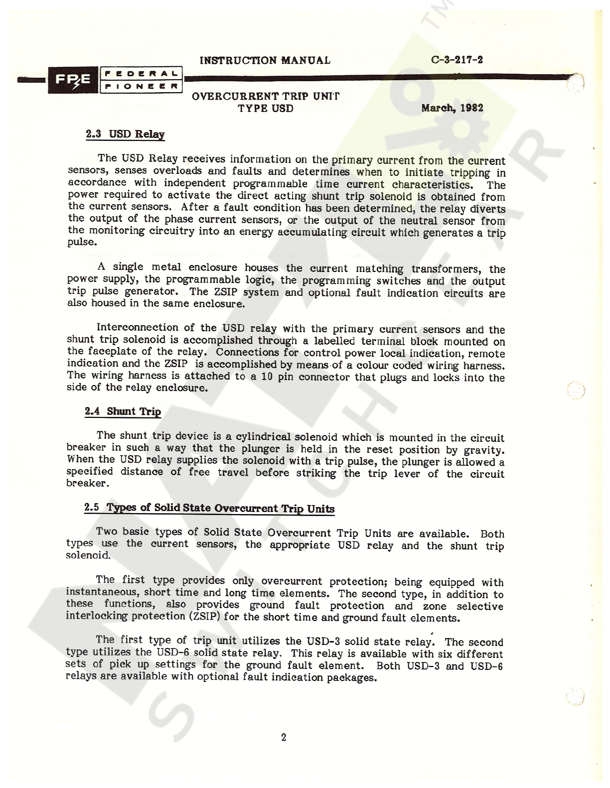
2.3
USD
Relay
The
USD
Relay
receives
information
on
the
primary
current
from
the
current
sensors
,
senses
overloads
and
faults
and
determines
when
to
initiate
tripping
in
accordance
with
independent
programmable
time
current
characteristics
.
The
power
required
to
activate
the
direct
acting
shunt
trip
solenoid
is
obtained
from
the
current
sensors
.
After
a
fault
condition
has
been
determined
,
the
relay
diverts
the
output
of
the
phase
current
sensors
,
or
the
output
of
the
neutral
sensor
from
the
monitoring
circuitry
into
an
energy
accumulating
circuit
which
generates
a
trip
pulse
.
A
single
metal
enclosure
houses
the
current
matching
transformers
,
the
power
supply
,
the
programmable
logic
,
the
programming
switches
and
the
output
trip
pulse
generator
.
The
ZSIP
system
and
optional
fault
indication
circuits
are
also
housed
in
the
same
enclosure
.
Interconnection
of
the
USD
relay
with
the
primary
current
sensors
and
the
shunt
trip
solenoid
is
accomplished
through
a
labelled
terminal
block
mounted
on
the
faceplate
of
the
relay
.
Connections
for
control
power
local
indication
,
remote
indication
and
the
ZSIP
is
accomplished
by
means
of
a
colour
coded
wiring
harness
.
The
wiring
harness
is
attached
to
a
10
pin
connector
that
plugs
and
locks
into
the
side
of
the
relay
enclosure
.
2.4
Shunt
Trip
The
shunt
trip
device
is
a
cylindrical
solenoid
which
is
mounted
in
the
circuit
breaker
in
such
a
way
that
the
plunger
is
held
in
the
reset
position
by
gravity
.
When
the
USD
relay
supplies
the
solenoid
with
a
trip
pulse
,
the
plunger
is
allowed
a
specified
distance
of
free
travel
before
striking
the
trip
lever
of
the
circuit
breaker
.
2.5
Types
of
Solid
State
Overcurrent
Trip
Units
Two
basic
types
of
Solid
State
Overcurrent
Trip
Units
are
available
.
Both
types
use
the
current
sensors
,
the
appropriate
USD
relay
and
the
shunt
trip
solenoid
.
The
first
type
provides
only
overcurrent
protection
;
being
equipped
with
instantaneous
,
short
time
and
long
time
elements
.
The
second
type
,
in
addition
to
these
functions
,
also
provides
ground
fault
protection
and
zone
selective
interlocking
protection
(
ZSIP
)
for
the
short
time
and
ground
fault
elements
.
4
The
first
type
of
trip
unit
utilizes
the
USD
-
3
solid
state
relay
.
The
second
type
utilizes
the
USD
-
6
solid
state
relay
.
This
relay
is
available
with
six
different
sets
of
pick
up
settings
for
the
ground
fault
element
.
Both
USD
-
3
and
USD
-
6
relays
are
available
with
optional
fault
indication
packages
.
2
Courtesy of NationalSwitchgear.com

INSTRUCTION
MANUAL
C
-
3
-
217
-
2
FEDERAL
PIONEER
f
OVERCURRENT
TRIP
UNIT
TYPE
USD
March
,
1982
3
.
OPERATION
3.1
General
The
functional
block
diagram
of
Figure
1
attached
,
illustrates
the
operation
of
the
USD
relay
.
Appropriate
blocks
are
eliminated
for
models
not
providing
ground
fault
protection
and
ZSIP
.
There
are
three
current
sensors
on
the
circuit
breaker
monitoring
the
primary
phase
current
.
If
ground
fault
protection
is
required
on
3
phase
4
wire
power
systems
,
a
fourth
sensor
must
be
used
.
The
current
sensors
supply
currents
to
the
relay
which
are
proportional
to
the
currents
in
the
primary
circuit
.
These
currents
are
converted
to
d
.
c
.
signals
by
means
of
a
set
of
residually
connected
auxiliary
transformers
and
a
set
of
rectifiers
.
These
signals
are
used
to
provide
energy
for
tripping
,
regulated
logic
power
supply
voltage
and
signals
proportional
to
the
gorund
and
phase
currents
.
The
relay
may
have
up
to
four
pickup
elements
;
INSTANTANEOUS
,
SHORT
TIME
,
LONG
TIME
and
GROUND
FAULT
.
Each
pickup
circuit
works
independently
of
the
other
and
triggers
its
corresponding
time
delay
circuit
.
The
instantaneous
element
has
no
intentional
time
delay
.
3.2
Overcurrent
Elements
Overload
and
short
circuit
protection
are
provided
jointly
by
the
LONG
TIME
,
SHORT
TIME
,
and
INSTANTANEOUS
elements
.
The
signal
in
the
relay
which
is
proportional
to
the
highest
of
the
three
phase
primary
current
is
compared
to
preset
values
in
each
of
the
three
elements
.
If
it
does
not
exceed
any
of
the
preset
pickup
levels
,
the
relay
continues
to
monitor
the
system
.
If
the
current
signals
exceed
a
preset
pickup
setting
,
the
respective
time
delay
circuit
will
start
timing
.
When
the
proper
time
delay
is
reached
,
the
relay
transfers
itself
into
a
fault
mode
.
The
output
from
the
phase
sensors
is
diverted
totally
into
the
energy
accumulating
circuit
.
When
enough
energy
has
been
accumulated
,
a
trip
pulse
is
supplied
to
the
shunt
trip
solenoid
.
The
LONG
TIME
element
has
the
inverse
(
I
2
t
=
constant
)
bands
.
The
SHORT
TIME
element
has
four
definite
time
bands
which
become
slightly
inverse
at
low
fault
levels
and
an
inverse
(
I
2
t
=
constant
)
band
.
The
LONG
TIME
element
has
ten
inverse
(
Inconstant
)
bands
.
The
INSTANTANEOUS
element
has
no
intentional
time
delay
other
than
that
needed
by
the
relay
to
initialize
itself
and
accumulate
trip
energy
.
All
I
2
t
functions
are
dynamic
in
behaviour
and
are
continuously
adjusting
the
time
rate
to
the
existing
maximum
phase
current
during
the
timing
operation
.
3.3
Ground
Fault
Element
The
input
signal
for
the
GROUND
FAULT
element
is
obtained
from
the
residually
connected
auxiliary
transformers
in
the
relay
.
This
allows
ground
current
detection
in
both
3
phase
3
wire
and
4
wire
systems
.
If
the
ground
current
signal
exceed
the
preset
pickup
value
,
the
ground
fault
time
delay
circuit
starts
timing
.
On
reaching
the
preset
time
delay
,
the
output
trip
circuit
is
activated
.
3
Courtesy of NationalSwitchgear.com

C
-
3
-
217
-
2
INSTRUCTION
MANUAL
FEDERAL
PIONEER
OVERCURRENT
TRIP
UNIT
TYPE
USD
March
,
1982
The
signal
output
representing
the
ground
current
is
diverted
into
the
energy
accumulating
circuit
and
ultimately
discharged
into
the
shunt
trip
solenoid
.
When
the
indication
is
provided
,
a
trip
caused
by
a
ground
fault
is
normally
registered
by
the
G
.
F
.
remotely
.
It
should
be
noted
,
however
,
that
since
ground
fault
current
is
also
phase
current
and
may
therefore
be
over
current
,
the
overcurrent
element
indicators
may
also
register
the
fault
.
The
ground
fault
element
has
5
time
bands
which
are
slightly
inverse
at
low
ground
fault
levels
,
because
of
the
time
needed
to
accumulate
trip
energy
,
and
become
definite
at
high
ground
fault
levels
.
indication
LED
,
locally
,
and
by
the
G
.
F
.
normally
open
contacts
,
3.4
The
ZSIP
Functions
Selectivity
between
the
main
breaker
and
feeder
breakers
is
conventionally
obtained
by
using
time
coordinated
trip
devices
.
The
time
delay
of
the
trip
device
furthest
downstream
is
set
to
minimum
and
it
increases
from
one
zone
to
the
next
with
the
main
breaker
'
s
trip
device
having
the
highest
time
delay
setting
.
The
disadvantage
of
this
method
is
that
as
the
fault
levels
increase
for
zones
closer
to
the
main
breaker
,
the
time
to
clear
faults
in
these
zones
increases
,
and
the
power
system
must
endure
the
high
current
fault
until
the
time
delay
expires
.
With
the
trip
devices
in
the
ZSIP
mode
,
the
trip
device
that
senses
a
fault
in
its
zone
proceeds
to
trip
immediately
.
It
also
sends
a
restraint
signal
to
the
upstream
trip
devices
and
causes
them
to
revert
to
their
time
coordinated
protection
mode
.
Therefore
instantaneous
protection
against
faults
is
provided
in
all
zones
.
In
the
USD
relay
,
the
ZSIP
is
available
on
the
SHORT
TIME
element
and
the
GROUND
FAULT
element
and
the
operation
is
based
on
the
above
concepts
.
The
transmission
of
the
SHORT
TIME
restraint
and
ground
fault
restraint
signals
is
achieved
via
one
pair
of
signal
wires
.
This
minimizes
the
number
of
auxiliary
terminals
on
the
breaker
and
the
number
of
wires
needed
for
this
purpose
.
To
achieve
transmission
of
two
singals
over
the
same
set
of
wires
,
the
USD
relay
is
equipped
with
an
encoder
which
conditions
the
outgoing
restraint
signals
and
a
decoder
to
separate
the
incoming
restraint
signals
and
restrain
the
appropriate
elements
.
3.5
Selecting
Settings
The
USD
relay
has
a
number
of
thumbwheel
switches
that
enable
the
user
to
program
the
desired
time
current
protection
profile
in
the
field
,
see
Figure
2
attached
.
The
thumbwheel
switches
are
accessible
on
the
front
panel
of
the
relay
through
a
cutout
in
the
faceplate
.
Each
switch
is
actuated
by
a
knurled
thumbwheel
and
the
selected
position
is
indicated
by
a
number
ranging
from
0
to
9
,
appearing
on
the
thumbwheel
.
The
correlation
between
the
dial
number
appearing
on
each
switch
and
the
pickup
level
or
time
delay
is
shown
on
a
table
adjacent
to
each
switch
.
The
contact
surfaces
of
these
switches
are
gold
plated
to
assure
long
lasting
and
positive
electrical
contact
.
Should
any
switch
contact
of
any
element
become
4
Courtesy of NationalSwitchgear.com

INSTRUCTION
MANUAL
C
-
3
-
217
-
2
FEDERAL
f
'
PIONEER
OVERCURRENT
TRIP
UNIT
TYPE
USD
March
,
1982
open
,
the
relay
will
automatically
operate
on
the
highest
setting
of
that
element
as
a
backup
protection
.
All
pickup
and
timing
functions
are
independent
of
each
other
.
The
selection
of
settings
are
therefore
governed
by
system
design
considerations
.
Relays
incorporating
the
ZSIP
function
are
equipped
with
a
screw
driver
actuated
,
3
position
,
rotary
switch
.
This
switch
,
available
on
the
faceplate
of
the
unit
,
enables
the
user
to
program
the
desired
mode
of
operation
.
The
first
position
of
the
switch
,
marked
ZSIP
means
that
both
short
time
and
ground
fault
elements
are
restrained
by
downstream
relays
to
prevent
instantaneous
operation
on
a
downstream
fault
.
The
second
position
,
marked
G
.
F
.
ZSIP
,
ST
,
TCP
(
Time
Coordinated
Protection
)
means
that
there
is
ZSIP
on
the
ground
fault
element
only
and
the
short
time
element
is
self
-
restrained
.
The
third
position
marked
TCP
means
that
both
ground
fault
and
short
time
elements
are
self
-
restrained
.
It
should
be
noted
that
the
position
of
this
switch
has
no
influence
on
the
restraint
out
signal
of
the
relay
.
This
feature
is
useful
when
the
last
relay
downstream
has
to
be
in
the
TCP
mode
while
upstream
relays
are
in
the
ZSIP
mode
.
4
.
SPECIFICATIONS
4.1
Scope
The
specifications
cover
the
USD
Solid
State
Overcurrent
Trip
System
for
use
on
the
Federal
Pioneer
Ltd
.
low
voltage
power
air
circuit
breakers
.
The
trip
unit
complies
with
the
American
National
Standard
for
trip
devices
for
a
.
c
.
low
voltage
circuit
breakers
(
ANSI
C
37.17
-
1972
)
.
4.2
Current
Sensor
Ratings
4.2
.
1
-
100
%
continuous
current
settings
are
available
at
;
3000
A
3200
A
4000
A
5000
A
6000
A
50
A
600
A
800
A
1000
A
1200
A
1600
A
2000
A
70
^
100
A
150
A
250
A
400
A
D
Courtesy of NationalSwitchgear.com

RDCTION
MANUAL
C
-
3
-
217
-
2
;
•
i
i
?
v
iCURRENT
TRIP
UNIT
TYPE
USD
1
‘
t
>
;
>
•
.
•
*
.
*
•
rvr
March
,
1982
»
•
>
.
v
.
y
V
\
}
V
••
•
*
•
*
•
v
:
sensors
available
along
with
the
taps
of
each
sensor
and
i
sizes
with
which
these
current
sensors
:
V
'
V
can
be
used
®
11
*
6
r
:
;
-
tion
characteristics
of
the
sensors
and
their
secondary
d
.
c
.
igure
3
attached
.
ations
V
X
\
y
:
i
t
y
.
H
.
*
.
options
available
with
each
model
are
detailed
in
Table
2
L
•
*
lement
0.6
X
,
0.7
X
,
0.8
X
,
0.9
X
,
1.0
X
,
1.1
X
the
up
settings
available
:
;
up
tolerance
:
+
8
%
based
on
symmetrical
sinusoidal
current
at
me
Delay
Bands
:
10
calibrated
bands
are
provided
ranging
from
l
2
t
=
72
seconds
to
I
^
t
=
1.080
seconds
(
I
in
per
unit
)
rime
delays
of
2
,
4
,
6
,
8
,
10
,
14
,
16
,
22
,
26
and
30
seconds
at
600
%
al
current
50
/
60
Hz
.
Time
Delay
Tolerance
:
+
10
%
based
on
symmetrical
sinusoidal
current
>
rt
Time
Element
Pickup
settings
available
:
2
X
,
3
X
,
4
X
,
6
X
,
8
X
,
and
10
X
the
sensor
1
-
Pickup
tolerance
:
+
8
%
based
on
symmetrical
sinusoidal
current
at
i
.
2
-
L
.
V
iSilSIii
fsglsf
1.5
.
3
-
Time
Delay
Bands
:
Four
definite
time
bands
with
nominal
time
;
of
0.11
second
,
0.25
second
,
0.33
second
,
0.45
second
and
an
inverse
band
I
2
t
8
second
(
I
in
per
unit
)
with
time
delay
of
0.55
seconds
at
600
%
rated
oidal
current
,
50
/
60
Hz
.
4.5
.
4
-
Time
Delay
tolerance
:
+
10
%
based
on
symmetrical
sinusoidal
current
i
0
/
60
Hz
.
4
*
.
/
,
•
v
-
The
SHORT
TIME
delay
in
the
ZSIP
mode
with
no
restraint
is
jproximately
50
m
seconds
regardless
of
the
SHORT
TIME
delay
setting
.
4.5
.
5
6
V
Courtesy of NationalSwitchgear.com
INSTRUCTION
MANUAL
C
-
3
-
217
-
2
FEDERAL
PIONEER
OVERCURRENT
TRIP
UNIT
TYPE
USD
March
,
1982
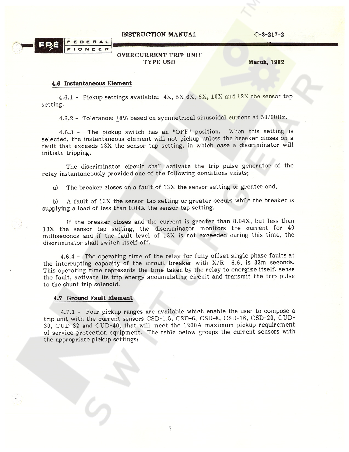
4.6
Instantaneous
Element
4.6
.
1
-
Pickup
settings
available
:
4
X
,
5
X
6
X
,
8
X
,
10
X
and
12
X
the
sensor
tap
setting
.
4.6
.
2
-
Tolerance
:
+
8
%
based
on
symmetrical
sinusoidal
current
at
50
/
60
Hz
.
4.6
.
3
-
The
pickup
switch
has
an
"
OFF
"
position
.
Vvhen
this
setting
is
selected
,
the
instantaneous
element
will
not
pickup
unless
the
breaker
closes
on
a
fault
that
exceeds
13
X
the
sensor
tap
setting
,
in
which
case
a
discriminator
will
initiate
tripping
.
The
discriminator
circuit
shall
activate
the
trip
pulse
generator
of
the
relay
instantaneously
provided
one
of
the
following
conditions
exists
;
a
)
The
breaker
closes
on
a
fault
of
13
X
the
sensor
setting
or
greater
and
,
b
)
A
fault
of
13
X
the
sensor
tap
setting
or
greater
occurs
while
the
breaker
is
supplying
a
load
of
less
than
0.04
X
the
sensor
tap
setting
.
If
the
breaker
closes
and
the
current
is
greater
than
0.04
X
,
but
less
than
13
X
the
sensor
tap
setting
,
the
discriminator
monitors
the
current
for
40
milliseconds
and
if
the
fault
level
of
13
X
is
not
exceeded
during
this
time
,
the
discriminator
shall
switch
itself
off
.
4.6
.
4
-
The
operating
time
of
the
relay
for
fully
offset
single
phase
faults
at
the
interrupting
capacity
of
the
circuit
breaker
with
X
/
R
6.6
,
is
33
m
seconds
.
This
operating
time
represents
the
time
taken
by
the
relay
to
energize
itself
,
sense
the
fault
,
activate
its
trip
energy
accumulating
circuit
and
transmit
the
trip
pulse
to
the
shunt
trip
solenoid
.
4.7
Ground
Fault
Element
4.7
.
1
-
Four
pickup
ranges
are
available
which
enable
the
user
to
compose
a
trip
unit
with
the
current
sensors
CSD
-
1.5
,
CSD
-
6
,
CSD
-
8
,
CSD
-
16
,
CSD
-
20
,
CUD
-
30
,
CUD
-
32
and
CUD
-
40
,
that
will
meet
the
1200
A
maximum
pickup
requirement
of
service
protection
equipment
.
The
table
below
groups
the
current
sensors
with
the
appropriate
pickup
settings
;
7
Courtesy of NationalSwitchgear.com

INSTRUCTION
MANUAL
C
-
3
-
217
-
2
FEDERAL
PIONEER
OVERCURRENT
TRIP
UNIT
TYPE
USD
March
,
1982
Pickup
Settings
(
Multiple
of
Sensor
Tap
)
Sensor
Type
CSD
-
1.5
CSD
-
6
CDS
-
16
0.2
,
0.3
,
0.4
,
0.5
,
0.6
,
0.7
0.2
,
0.25
,
0.3
,
0.4
,
0.5
,
0.6
CSD
-
20
CUD
-
30
CUD
-
32
0.2
,
0.22
,
0.24
,
0.28
,
0.32
,
0.36
CUD
-
40
CUD
-
60
0.2
,
0.22
,
0.24
,
0.26
,
0.28
,
0.30
4.7
.
2
-
Tolerance
:
+
8
%
based
on
symmetrical
sinusoidal
current
at
50
/
60
Hz
.
4.7
.
3
-
Time
Delay
Bands
:
5
calibrated
bands
are
provided
that
are
slightly
inverse
at
low
fault
levels
and
become
definite
at
fault
levels
exceeding
500
%
rated
current
.
The
definite
time
delays
provided
are
0.08
,
0.14
,
0.20
,
0.26
,
and
0.32
seconds
.
In
the
inverse
region
these
become
0.17
,
0.23
,
0.29
,
0.35
,
0.40
seconds
with
100
%
rated
current
.
Time
Delay
tolerance
:
+
10
%
based
on
symmetrical
sinusoidal
4.7
.
4
current
at
50
/
60
Hz
.
In
the
ZSIP
mode
with
no
restraint
,
the
ground
fault
element
initiates
tripping
approximately
20
m
seconds
after
pickup
occurs
.
The
time
current
characteristics
in
Figure
4
attached
should
be
consulted
for
the
operating
time
of
the
relay
under
currents
other
than
those
specified
here
.
4.7
.
5
8
Courtesy of NationalSwitchgear.com

INSTRUCTION
MANUAL
C
-
3
-
217
-
2
FEDERAL
PIONEER
OVERCURRENT
TRIP
UNI
T
TYPE
USD
March
,
1982
4.8
Output
Trip
Pulse
The
USD
relay
provides
a
trip
pulse
output
with
a
minimum
energy
of
0.98
joules
.
This
pulse
has
an
initial
voltage
of
140
V
and
its
rate
of
decay
depends
on
the
impedance
of
the
shunt
trip
solenoid
.
This
energy
is
approximately
that
stored
in
a
100
F
capacitor
charged
to
140
V
d
.
c
.
4.9
Test
Signals
A
test
plug
is
mounted
on
the
faceplate
of
the
relay
to
provide
access
to
appropriate
signals
so
that
the
operation
of
the
relay
can
be
checked
by
means
of
a
Test
Set
or
other
metering
devices
.
The
signals
available
on
the
test
plug
are
;
PIN
#
SIGNAL
Test
Set
input
signal
t
!
1
2
3
4
Instantaneous
pickup
/
inhibit
Short
time
pickup
/
inhibit
Long
time
pickup
/
inhibit
Ground
fault
pickup
/
inhibit
Overcurrent
trip
inhibit
Logie
common
Ground
fault
trip
signal
(
delay
)
Overcurrent
trip
signal
(
delay
)
5
6
7
8
9
10
11
12
4.10
Relay
Impedance
(
Burden
)
The
impedance
of
the
overcurrent
elements
and
ground
fault
element
seen
by
the
secondary
of
the
current
sensors
at
different
current
levels
are
shown
in
Figures
5
a
and
5
b
attached
.
4.11
Reset
Time
If
a
fault
condition
disappears
and
the
current
magnitude
drops
to
95
%
of
the
pickup
level
of
any
element
,
the
relay
resets
in
approximately
30
m
seconds
.
If
the
breaker
trips
,
the
signals
to
the
relay
disappear
and
the
relay
resets
automatically
.
The
fault
indicators
,
if
used
,
must
be
reset
manually
with
the
pushbutton
on
the
relay
faceplate
.
9
Courtesy of NationalSwitchgear.com

INSTRUCTION
MANUAL
C
-
3
-
217
-
2
FEDERAL
PIONEER
OVERCURRENT
TRIP
UNIT
TYPE
USD
March
,
1982
Under
arcing
ground
fault
conditions
,
the
ground
fault
element
of
the
USD
operates
to
carry
through
the
missing
cycles
or
half
cycles
in
the
definite
time
region
and
trip
.
In
the
inverse
region
where
energy
accumulation
contributes
considerably
to
the
delay
,
the
arcing
ground
fault
is
integrated
with
time
and
a
trip
is
generated
as
soon
as
trip
energy
has
been
accumulated
.
4.12
Performance
in
Service
The
circuits
in
the
USD
relay
are
stable
and
show
excellent
repeatability
over
long
periods
of
time
.
Service
involving
frequent
operations
will
not
cause
the
characteristics
to
change
or
drift
,
since
there
are
no
mechanical
moving
parts
to
wear
.
The
USD
relay
is
compensated
for
variations
in
ambient
temperature
over
the
range
-
20
°
C
to
+
55
°
C
.
The
tolerance
over
this
temperature
range
is
+
8
%
on
the
pickup
and
+
10
%
on
the
time
delay
of
all
the
elements
.
Operation
outside
this
temperature
range
is
possible
,
factory
for
further
information
,
specifying
the
required
temperature
range
.
Consult
the
TESTING
5
.
5.1
Secondary
Injection
Testing
of
the
overcurrent
trip
system
with
secondary
injection
is
easily
accomplished
,
under
field
conditions
,
with
the
Federal
Pioneer
portable
Test
Set
Type
DDT
-
USD
.
The
test
can
be
done
on
a
complete
breaker
assembly
located
in
the
disconnect
position
in
the
cubicle
,
on
the
complete
breaker
on
a
work
bench
,
or
on
a
static
trip
device
completely
removed
from
the
breaker
.
It
is
not
necessary
,
however
,
to
remove
any
wiring
in
order
to
do
any
of
these
tests
.
The
type
DDT
-
USD
test
unit
permits
checking
pickup
and
timing
functions
as
well
as
the
operation
of
the
shunt
trip
solenoid
.
The
type
DDT
-
USD
test
unit
can
,
in
addition
,
check
the
functions
of
the
trip
unit
with
the
circuit
breaker
in
service
.
The
Instruction
Manual
C
-
3
-
217
-
4
of
the
test
unit
should
be
consulted
.
5.2
Primary
Injection
5.2
.
1
If
it
is
desired
to
check
the
current
sensor
operation
it
will
be
necessary
to
test
the
breaker
by
primary
current
injection
methods
.
This
involves
connecting
the
power
poles
of
the
breaker
to
a
controlled
source
of
current
.
The
advantage
of
this
system
is
that
the
entire
sensor
-
relay
-
trip
coil
system
operation
is
verified
.
The
disadvantage
is
that
suitable
equipment
required
for
such
testing
is
heavy
,
extensive
and
difficult
to
use
.
10
Courtesy of NationalSwitchgear.com
INSTRUCTION
MANUAL
C
-
3
-
217
-
2
FEDERAL
PIONEER
OVERCURRENT
TRIP
UNIT
TYPE
USD
March
,
1982
5.2
.
2
The
test
equipment
for
single
phase
tests
should
provide
50
/
60
Hz
.
sinuisoidal
current
to
the
breaker
power
pole
terminals
.
The
connectors
to
double
-
stab
poles
(
on
higher
current
breakers
)
should
be
arranged
to
divide
the
current
between
the
two
stabs
equally
.
If
complete
testing
of
all
pickup
positions
of
the
USD
is
desired
the
test
equipment
should
be
capable
of
1200
%
of
the
breaker
current
rating
for
at
least
.
04
seconds
and
600
%
of
the
current
rating
for
30
seconds
.
For
minimum
testing
the
test
equipment
should
be
capable
of
600
%
current
rating
for
at
least
2
seconds
.
This
will
enable
testing
on
all
elements
to
be
performed
on
the
lowest
settings
for
INSTANTANEOUS
PICKUP
,
SHORT
TIME
PICKUP
and
LONG
TIME
DELAY
elements
.
5.2
.
3
The
test
equipment
should
include
a
timer
which
starts
when
the
current
is
switched
on
and
stops
when
the
current
is
switched
off
(
breaker
trips
)
.
It
should
be
capable
of
measuring
time
intervals
from
.
01
seconds
to
2000
seconds
accurately
.
5.2
.
4
The
open
circuit
voltage
of
the
current
souce
must
be
at
least
10
volts
when
set
at
the
test
current
.
5.2
.
5
Test
connections
to
the
breaker
should
be
as
short
as
possible
,
otherwise
,
current
capability
will
be
limited
and
only
minimum
testing
achieved
.
5.2
.
6
Before
attempting
testing
the
USD
relay
,
the
element
and
setting
to
be
tested
must
be
decided
.
To
ensure
that
other
elements
do
not
interfere
with
the
test
it
will
be
necessary
to
set
pickup
and
/
or
delay
settings
higher
than
those
under
test
.
5.2
.
7
For
USD
-
6
types
mounted
in
drawout
breakers
removed
from
the
cubicle
it
will
be
necessary
to
connect
a
test
jumper
to
complete
the
secondary
circuit
between
the
sensors
and
the
USD
relay
terminals
since
the
current
is
normally
completed
by
a
permanent
jumper
or
external
sensor
,
depending
on
the
type
of
system
being
used
.
The
jumper
may
be
connected
to
the
contacts
of
the
rear
mounted
terminal
blocks
as
shown
in
Figure
8
.
The
actual
terminals
used
varies
from
one
breaker
to
another
,
the
requiring
use
of
the
appropriate
breaker
wiring
diagram
to
determine
actual
location
.
5.2
.
9
For
overcurrent
tests
(
not
ground
fault
)
jumper
A
only
must
be
installed
.
For
ground
fault
tests
jumper
B
only
must
be
installed
.
5.2
.
8
5.2
.
10
Alternatively
,
the
connections
may
be
made
directly
from
the
common
terminal
of
the
sensors
to
either
the
N
or
G
terminal
of
the
relay
for
overcurrent
or
ground
fault
tests
respectively
.
5.2
.
11
It
is
necessary
to
provide
120
VAC
,
2.5
VA
control
power
if
it
is
desired
to
check
indication
lamps
or
remote
outputs
.
11
Courtesy of NationalSwitchgear.com
INSTRUCTION
MANUAL
C
-
3
-
217
-
2
FEDERAL
PIONEER
OVERCURRENT
TRIP
UNIT
TYPE
USD
March
,
1982
5.2
.
12
To
check
ZSIP
functions
it
will
be
necessary
to
connect
a
RESTRAINT
signal
to
obtain
time
delay
operation
of
GROUND
FAULT
and
SHORT
TIME
elements
(
otherwise
trip
will
be
instantaneous
)
.
This
can
be
achieved
by
using
a
SELF
RESTRAINT
method
whereby
a
test
jumper
is
connected
between
RESTRAINT
OUT
and
RESTRAINT
IN
terminals
(
on
the
side
mounted
10
pin
plug
)
.
A
switch
may
be
wired
for
convenient
control
as
shown
in
Figure
8
.
5.2
.
13
For
USD
-
6
types
used
with
fixed
breakers
,
a
direct
connection
between
the
sensor
common
and
either
the
N
or
G
terminals
of
the
USD
will
allow
testing
of
overcurrent
or
ground
fault
respectively
.
5.2
.
14
After
each
test
in
which
the
breaker
has
tripped
,
it
must
again
be
charged
and
closed
before
proceeding
with
the
next
test
.
5.2
.
15
After
the
conclusion
of
the
tests
the
relay
settings
must
be
restored
to
their
original
values
.
The
jumper
,
if
any
,
should
be
removed
from
the
auxiliary
contacts
.
The
arcing
and
main
and
main
contacts
of
the
breaker
must
be
inspected
and
serviced
as
required
by
the
breaker
Manual
C
-
3
-
233
.
5.2
.
16
Care
should
be
taken
when
using
magnetic
pickup
devices
for
measuring
current
(
eg
.
clip
-
on
ammeters
,
current
sensors
etc
)
to
ensure
that
the
readings
are
not
being
influenced
by
the
strong
magnetic
field
from
high
-
current
carrying
conductors
.
5.2
.
17
Since
the
published
characteristics
are
defined
for
ideal
testing
arrangements
,
additional
tolerances
may
be
required
to
allow
for
field
conditions
(
eg
.
wareforms
may
not
be
sinusoidal
)
.
The
trip
time
of
the
breaker
should
also
be
added
to
time
delay
measurements
(
approximately
half
a
cycle
)
when
performing
primary
current
injection
tests
.
CAUTION
Since
much
of
the
testing
involves
currents
considerably
higher
than
the
continuous
ratings
of
the
breaker
and
the
trip
device
,
care
should
be
exercised
in
not
overheating
it
.
Sufficient
cooling
time
must
be
allowed
between
tests
.
6
.
MAINTENANCE
6
J
General
Each
Solid
State
Overcurrent
Relay
is
tested
and
calibrated
before
shipment
.
It
is
ready
for
use
after
it
has
been
interconnected
with
the
rest
of
the
components
of
the
trip
unit
and
the
appropriate
settings
have
been
selected
.
The
only
maintenance
recommended
is
the
periodic
verification
that
the
relay
is
functioning
.
This
may
be
supplemented
as
desired
by
checking
the
calibration
and
inspection
for
loose
or
broken
external
wiring
.
12
Courtesy of NationalSwitchgear.com

INSTRUCTION
MANUAL
C
-
3
-
217
-
2
FEDERAL
PIONEER
OVERCURRENT
TRIP
UNIT
TYPE
USD
March
,
1982
6.2
Troubleshooting
6.2
.
1
-
Failure
to
Trip
:
Failure
of
the
circuit
breaker
to
trip
in
response
to
a
fault
may
be
caused
by
any
of
the
reasons
listed
below
.
Corrective
action
is
indicated
with
the
reason
for
failure
to
trip
.
(
a
)
Relay
set
too
high
-
check
that
the
pickup
settings
on
the
relay
are
correct
and
that
the
correct
sensor
tap
is
used
,
(
b
)
Sensors
improperly
connected
-
check
that
all
connections
are
tight
,
wiring
is
correct
and
leads
not
broken
.
Any
current
sensor
with
open
-
circuited
secondary
must
be
replaced
.
(
c
)
Shunt
trip
solenoid
open
-
circuited
-
check
that
the
wiring
to
the
trip
solenoid
is
not
broken
.
The
d
.
c
.
resistance
of
the
coil
should
be
approximately
30
ohms
.
6.2
.
2
-
Failure
to
Close
;
Failure
of
the
circuit
breaker
to
close
and
latch
mechanically
may
be
due
to
the
reasons
listed
below
.
Corrective
action
is
as
indicated
.
(
a
)
The
shunt
trip
solenoid
-
check
to
ensure
that
the
plunger
of
the
shunt
trip
solenoid
is
not
inhibited
from
resetting
.
Refer
to
the
circuit
breaker
instruction
manual
for
mechanical
mounting
details
.
(
b
)
Ensure
that
an
overload
or
short
circuit
does
not
exist
in
the
load
circuit
.
(
c
)
Check
that
there
is
no
ground
current
exceeding
the
pickup
setting
.
Check
sensor
taps
to
ensure
that
the
setting
is
properly
selected
for
the
required
load
.
Check
sensor
wiring
and
mounting
for
marked
polarity
.
A
reverse
connected
current
sensor
generates
a
high
residual
current
which
causes
the
Ground
Fault
element
of
the
relay
to
trip
the
breaker
.
Check
that
pickup
and
delay
settings
are
such
as
to
override
certain
predictable
short
term
overloads
,
such
as
;
motor
starting
,
spot
welding
,
induction
oven
feeds
,
etc
.
Nonsinusoidal
current
may
cause
premature
tripping
since
the
solid
state
relay
incorporated
peak
responding
circuits
for
pickup
.
(
d
)
(
e
)
(
f
)
If
none
of
the
above
helps
,
the
USD
relay
must
be
tested
with
a
DDT
-
USD
test
unit
,
if
one
is
available
.
It
may
then
be
decided
that
the
relay
must
be
returned
to
Federal
Pioneer
for
repairs
.
In
such
a
case
it
will
be
a
great
help
to
the
Service
Department
if
the
source
of
complaint
is
documented
and
reported
as
accurately
as
possible
.
The
element
which
fails
to
function
properly
along
with
the
13
Courtesy of NationalSwitchgear.com

INSTRUCTION
MANUAL
C
-
3
-
217
-
2
•
u
FEDERAL
PIONEER
OVERCURRENT
TRIP
UNIT
TYPE
USD
•
ft
*
March
,
1982
Also
,
the
condition
under
which
improper
etting
or
settings
must
be
noted
,
iperation
was
noted
ie
.
during
initial
testing
,
during
maintenance
,
etc
.
and
the
type
jf
testing
equipment
used
.
This
will
enable
the
quick
repair
and
return
of
the
unit
.
wmm
t
*
-
85
i
-
s
A
:
%
»
•
.
i
)
14
Courtesy of NationalSwitchgear.com
Popular Power Distribution Unit manuals by other brands


Raritan
Raritan Dominion Px Quick setup guide

Xtreme Power Conversion
Xtreme Power Conversion SPD-0215 User & installation manual

Cyber Power
Cyber Power PDU81001 user manual

Hugo Lahme
Hugo Lahme VitaLight 40600250 user manual

CAYMON
CAYMON PSR529 Series quick start guide

Marway
Marway Optima 533 Series manual