13,3 V (± 0,3 V). Las tensiones que están en medio se pueden ajustar con progresión
continua. Recomendamos poner el regulador a una posición media. Entonces el módulo
desconecta a aprox. 11,7 V (± 0,3 V) y eso es óptima para la vida útil del acumulador. Si
Vd. elige un ajuste más pequeño, la capacidad del acumulador se utiliza sin duda a un
nivel más alto pero la vida útil se reduce considerablemente.
Nota: Un nuevo acumulador 12 V pleno tiene una tensión de aprox. 13,5 - 14 V.
Importante:
El módulo siempre conecta solamente con un retraso para que no desconecte et conecte
de nuevo por uctuaciones de tensión a corto plazo en virtud de alcanzes de corriente a
corto plazo. Al ajustar siempre esperar algunos minutes hasta que el módulo reaccione.
Listadecomprobaciónparalalocalizacióndefallas:
¡Al emplear cables demasiado delgados o largos, pérdidas de tensión ocurren en el cable
y el módulo desconecta permanentemente!
Informaciónimportante:
Ambas conexiones de la carga conectada no se deben conectar con “masa” (chasis). Ra-
zón: El módulo conecta o desconecta el polo negativo. Si estas conexiones son conecta-
das con “masa” respectivamente, el módulo sería puenteado por la “conexión a masa”
y sería inecaz.
Datostécnicos:
Tensióndeservicio: acumulador 12 V |Potenciaderupturamáxima:20 A (10 A
sin refrigeración, 20 A con refrigeración adicional) |Tensióndedesconexiónajus-
table:aprox. 10,4 - 13,3 V |Tensióndereconexión: aprox. 0,8 V (± 0,3 V) más que
la tensión de desconexión ajustada |Elementodedesconexión: Power MOS tran-
sistor en la línea negativa |Consumodeelectricidadindependiente: < 0,7 mA en
estado “desconectado”, < 1,6 mA en estado “conectado” (LED se ilumina) |Medidas:
aprox. 87 x 60 x 33 mm (con fondo de jación)
Usageprévu:
Protection d’une batterie pour auto contre décharge profonde par dissipateurs raccordés
en pavillons, tentes de camping, caravanes garés, etc.
Instructionsd’assemblage:
Installer le module de manière que qu’il ne soit pas exposé ni à l’humidité, ni aux vibra-
tions puissants ni à chaleur forte. Liez les raccords avec la batterie et le dissipateur selon
le dessin. Veuillez employer des câbles avec une coupe transversale sufsante (si possible
> 1,5 mm²) pour éviter des pertes de charge trop hautes dans le câble.
Il est absolument nécessaire d’intercaler un fusible de sécurité selon le dessin!
Attention: Des court-circuits ou surcharge de côté du dissipateur du module peuvent cau-
ser un défaut du module qu’ensuite ne déconnecte plus! Comme la fonction de chaque
module était examiné soigneusement avant l’envoi, un remplacement gratuit n’est pas
possible en ces cas, ni en cas d’endommagement par une tension trop haute (> 15 V)!
La plaque de base métallique du module peut chauffer selon la charge. En cas de char-
ges de courant jusqu’à env. 10 A un refroidissement additionnel n’est pas nécessaire.
Mais on devrait installer le module «bien ventilé» de sorte que chaleur qui apparaît
éventuellement puisse être déversée de la plaque métallique par circulation d’air. En cas
de courants plus hauts de 10 - 20 A il faut monter le module avec la plaque métallique
planement sur une autre plaque métallique plus grande an que la chaleur soit déversée.
Nous recommandons une plaque d’env. 10 x 15 x 0,5 cm ou quelque chose semblable
avec un effet de refroidissement similaire. Pendant la marche continue la plaque de base
du module ne doit pas chauffer à plus de 70°C.
Vous pouvez ajuster la tension de rupture avec le petit condensateur ajustable à côté
des bornes à che. Quand le régulateur est tourné complètement à l’arrêt à la gauche,
le module déconnecte à env. 10,4 V (± 0,3 V) et à l’arrêt à droite à env. 13,3 V (± 0,3
V). Les tensions qui se trouvent entre les deux peuvent être réglées en continu. Nous re-
commandons de mettre le régulateur à position centrale. Ensuite le module déconnecte à
env. 11,7 V (± 0,3 V) et ceci est optimal pour la durée de vie de l’accu. Si vous choisissez
un ajustage plus bas, il est vrai que la capacité de l’accu est exploitée plus haut mais la
durée de vie diminue considérablement.
Renseignement: Un nouveau accu 12 V plein a une tension d’env. 13,5 - 14 V.
Important:
Le module commute toujours avec un retard an qu’il ne déconnecte et connecte de
nouveau à cause des uctuations de tension à court terme en vertu des augmentations
de courant à court terme. Lors du réglage veuillez toujours attendre quelques minutes
jusqu’à ce le module réagisse.
Listedecontrôlepourlarecherchedespannes:
Quand vous employez des câbles trop minces ou trop longs, des pertes de charge se
montrent dans le câble et le module déconnecte continuellement!
Indicationimportante:
Il ne faut pas connecter les raccords de la charge raccordée avec «masse» (châssis).
Raison: Le module connecte ou déconnecte le pôle négatif. Si ces raccords sont connec-
tés avec «masse» chaque fois, le module serait ponté par la «connexion à la masse» et
serait sans effet.
Donnéestechniques:
Tensiondeservice: accu 12 V |Capacitéderupturemax.:20 A (10 A sans ref-
roidissement, 20 A avec refroidissement additionnel)|Tensionderupture: ajustable
d’env. 10,4 - 13,3 V |Tensionderéenclenchement: env. 0,8 V (± 0,3 V) plus que
la tension de rupture ajustée |Élémentdedéconnexion:transistor de type Power
MOS dans la ligne négative |Consommationd’électricitépropre: < 0,7 mA en état
„arrêt“, < 1,6 mA en état « marche » (DEL est allumée) |Dimensions: env. 87 x 60 x
33 mm (avec fond de xation)
Specialetoepassing:
Beschermd uw accu bij een te hoog stroom verbruik (bijv. op de camping met verlichting).
Montagetips:
Bij montage van het moduul moet gelet worden op vochtigheid, trillingen en hitte. Dit
moet zoveem als mogelijk voorkomen worden. Het moduul wordt volgens aansluitsche-
ma aan het verbruiksapparaat en de accu aangesloten. Gebruik een zo dik mogelijke
draad (dikker dan > 1,5 mm²), om zo weinig mogelijk spanningsverlies te hebben door
de draad.
Het is aan te raden om een zekering volgens tekening te monteren.
Let op: Bij kortsluiting of overbelasting (> 15 V) van het verbruiksapparaat aan de kant
van het moduul kan er voor zorgen dat het moduul defect wordt en niet meer uitscha-
keld. Omdat ieder moduul voor verzending zorgvuldig is gecontroleerd is er geen aan-
spraak op garantie of vergoeding.
De metalen bodemplaat kan bij het moduul, afhankelijk van de belasting, opwarmen.
Tot een laadstroom van ca. 10 A is geen extra koeling verplicht, maar moet zo worden
gemonteerd dat er een goede ventilatie aanwezig is. Bij hoge stromen 10 - 20 A moet de
metalen plaat van het moduul op een andere grotere plaat gemonteerd worden, zodat
de warmte afgevoerd kan worden. Aan te raden is een metalen plaat van ca. 10 x 15 x
0.5 cm, of iets anders met een goede koeling, zodat de bodemplaat van het moduul niet
boven de 70°C uitkomt.
U kunt met een instelpotmeter die naast de faston aansluiting zit, de uitschakelspanning
instellen.
Als de instelpotmeter helemaal naar links gedraait is, schakelt het moduul bij ca. 10.4 V (
± 0.3 V) uit, en bij het helemaal naar rechts draaien ca. 13.3 V (± 0.3 V) uit, daar tussen
kan traploos de gewenste spanning ingesteld worden. Wij raden aan de instelpotmeter
in het midden te regelen, ca, 11.7 V (± 0.3 V), dit geeft een langer levensduur voor de
accu. Mocht u voor een kortere instelling kiezen, wordt er meer van de capaciteit gebruik
gemaakt, wat inhoud dat de levensduur van de accu beduidend korter is.
Tip: een “volle”accu, nieuwe 12 V accu heeft een spanning van ca. 13.5 - 14 V.
Belangrijk:
Het moduul schakelt in altijd met een tijdvertraging, zodat het door kortstondige belas-
tingen, niet iedere keer in- en uitschakelt. Wacht altijd enkele minuten totdat het moduul
reageert.
Foutzoekcontrolelijst:
Als u een te dunne kabel gebruikt of de kabel is te lang, krijgt u spanningsverlies en het
moduul schakeld constant uit.
Belangrijketips:
De aansluitingen van aangesloten apparaten mogen niet aan “massa” of chassis ver-
bonden zijn. Reden: het moduul schakelt de minpool aan of uit. Als dit toch met de
“massa” verbonden is, dan zal het moduul door deze aansluiting weggedrukt worden en
functioneert niet.
Technischegegevens:
Voedingsspanning: 12 V accu |Max.schakelstroom: 20 A (10 A zonder koeling, 20
A d.m.v. extra koeling die niet bijgeleverd is) |Uitschakelspanning: instelbaar ca. 10.4
- 13.3 V |Nieuweinschakelspanning: moet ca. 0.8 V hoger zijn dan de ingestelde
uitschakelspanning |Uitschakelcomponent: Power-mos transistor in de min leiding |
Ruststroomverbruik:< 0.7 mA in uit schakeling, < 1.6 mA in aan schakeling (led licht
op) |Afmeting: ca. 87 x 60 x 33 mm (met bodemplaat)
Usoconformeasdisposiçõeslegais:
Protege uma bataria de carro contra cargas baixas através ligados consumidores em
caramanchão, tendas de campismo, carros de campismo estacionados etc.
Instruçõesdemontagem:
O modulo é montado de modo que este não esteja exposto a humidade, vibrações fortes
ou grandes calores. As ligações são ligadas com a bataria em volta do consumidor confor-
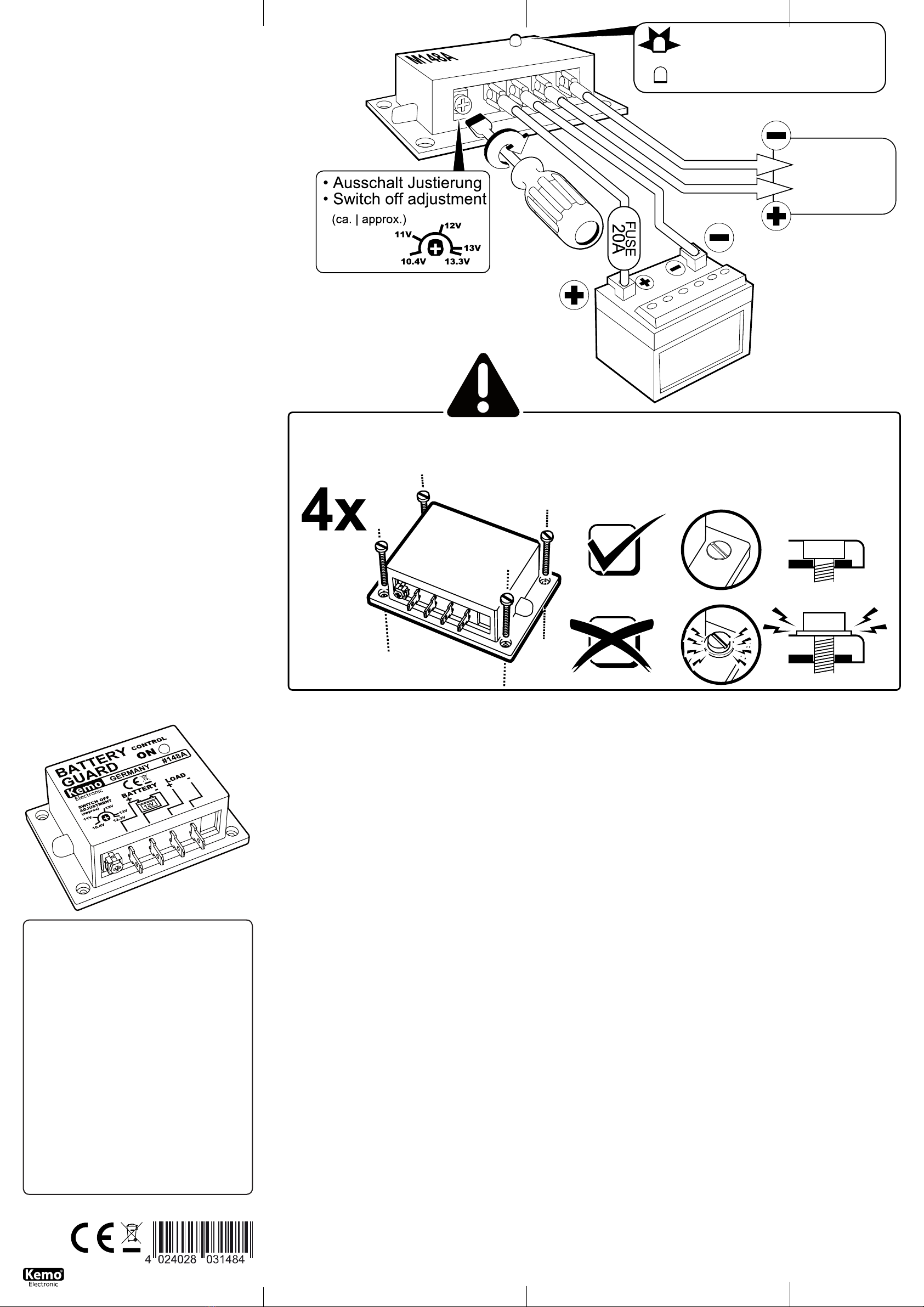
BestimmungsgemäßeVerwendung:
Schutz einer Autobatterie gegen Tiefentladung durch angeschlossene Verbraucher
in Gartenlauben, Campingzelten, parkenden Campingwagen usw.
Aufbauanweisung:
Das Modul wird so eingebaut, dass es keiner Feuchtigkeit, starken Vibrationen oder
großer Hitze ausgesetzt wird. Die Anschlüsse werden gemäß Zeichnung mit der
Batterie und dem Verbraucher verbunden. Bitte verwenden Sie Kabel mit einem
ausreichenden Querschnitt (möglichst > 1,5 mm²), damit keine zu hohen Span-
nungsverluste im Kabel auftreten.
Es ist dringend erforderlich eine Sicherung, gemäß Zeichnung, vorzuschalten!
Achtung: Kurzschlüsse oder Überlastung auf der Verbraucherseite des Moduls kön-
nen dazu führen, dass das Modul defekt wird und dann nicht mehr abschaltet!
Weil jedes Modul vor dem Versand sorgfältig auf Funktion geprüft wurde, ist in
solchen Fällen und auch bei einer Beschädigung mit zu hoher Spannung (> 15 V)
ein Kulanzersatz nicht möglich!
Die Metall-Grundplatte des Moduls kann sich, je nach Belastung, erwärmen. Bei
Lastströmen bis ca. 10 A ist keine zusätzliche Kühlung erforderlich. Das Modul
sollte aber „gut belüftet“ eingebaut werden, damit evtl. auftretende Wärme durch
Luftzirkulation von der Metallplatte abgeleitet wird. Bei höheren Strömen 10 - 20
A muss das Modul mit der Metallplatte plan auf eine andere, größere Metallplatte
gebaut werden, damit die Wärme abgeleitet wird. Wir empfehlen eine Platte ca.
10 x 15 x 0,5 cm oder etwas Ähnliches mit ähnlicher Kühlwirkung. Die Grundplatte
des Moduls darf sich im Dauerbetrieb nicht über 70°C erwärmen.
Sie können mit dem kleinen Trimmer neben den Steckanschlüssen die Abschalt-
spannung einstellen. Wenn der Regler ganz zum Anschlag links gedreht ist, schal-
tet das Modul bei ca. 10,4 V (± 0,3 V) ab und am Anschlag rechts bei ca. 13,3 V (±
0,3 V) ab. Dazwischen können stufenlos dazwischen liegende Spannungen einge-
stellt werden. Wir empfehlen, den Regler auf eine Mittelstellung zu bringen. Dann
schaltet das Modul bei ca. 11,7 V (± 0,3 V) ab und das ist für die Lebensdauer
des Akkus optimal. Wenn Sie eine kleinere Einstellung wählen, wird die Kapazität
des Akkus zwar höher ausgenutzt, aber die Lebensdauer reduziert sich erheblich.
Hinweis:Ein voller, neuer 12 V-Akku hat eine Spannung von ca. 13,5 - 14 V.
Wichtig:
Das Modul schaltet immer erst mit einer Zeitverzögerung, damit es nicht wegen
kurzfristiger Spannungsschwankungen aufgrund kurzfristiger Stromerhöhungen
ab- und wieder einschaltet. Bitte warten Sie bei der Einstellung immer ein paar
Minuten, bis das Modul reagiert.
ChecklistefürFehlersuche:
Wenn Sie zu dünnes Kabel verwenden oder die Kabel zu lang sind, dann kommt es
zu Spannungsverlusten im Kabel und das Modul schaltet ständig ab!
WichtigerHinweis:
Die Anschlüsse der angeschlossenen Last dürfen nicht mit einer „Masse“ (Chassis)
verbunden werden. Grund: Das Modul schaltet den Minuspol ein oder aus. Wenn
diese Anschlüsse jeweils mit „Masse“ verbunden sind, dann würde das Modul
durch den „Masseanschluss“ überbrückt werden und wäre wirkungslos.
TechnischeDaten:
Betriebsspannung: 12 V Akku |Max.Schaltleistung:20 A (10 A ohne Küh-
lung, 20 A mit zusätzlicher Kühlung) |Abschaltspannung: einstellbar ca. 10,4
- 13,3 V|Wiedereinschaltspannung:ca. 0,8 V (± 0,3 V) höher als die ein-
gestellte Abschaltspannung | Abschaltelement: Power-MOS-Transistor in der
Minusleitung |Eigenstromverbrauch: < 0,7 mA im Aus-Zustand, < 1,6 mA im
Ein-Zustand (LED leuchtet) |Maße:ca. 87 x 60 x 33 mm (mit Befestigungsboden)
Intendeduse:
Protection of a car battery against total discharge through connected consumers in
summer houses, camping tents, parking caravans etc.
Mountinginstructions:
The module is installed in such a manner that it is not exposed to humidity, strong
vibrations or great heat. The connections are linked with the battery and consu-
mer according to the drawing. Please use cables with a sufcient cross section (if
possible > 1.5 mm²), so that a too high loss of voltage in the cable is avoided.
It is absolutely necessary to superpose a safety fuse according to the drawing!
Attention: Short-circuits or overload on the consumer side of the module may
cause that the module will be damaged and then does not switch off any longer!
Due to the fact that the function of each module has been tested thoroughly before
dispatch, replacement at our expense is not possible in such cases or in case of
damage due to too high voltage (> 15 V)!
The metal base plate of the module may heat up depending on the load. No addi-
tional cooling is required for load currents up to approx. 10 A. The module should,
however, be installed “well ventilated” so that any heat that may possibly occur is
carried off from the metal plate through circulation of air. In case of higher currents
10 - 20 A the module has to be mounted with a metal plate planely on another
larger metal plate so that the heat will be carried off. We recommend a plate of
approx. 10 x 15 x 0.5 cm or the like with a similar cooling effect. The base plate
of the module must not heat up to more than 70°C during continuous operation.
The interrupting voltage may be adjusted with the small adjustable capacitor next
to the plug-in connections. If the controller is turned completely to the left stop,
the module disconnects at approx. 10.4 V (± 0.3 V) and at the right stop at approx.
13.3 V (± 0.3 V). Voltages lying in between can be adjusted continuously. We re-
commend to set the controller to a middle position. The module then disconnects
at approx. 11.7 V (± 0.3 V) and this is optimal for the lifetime of the accumulator.
When choosing a lower adjustment the capacity of the accumulator is indeed uti-
lized to a higher extent but the lifetime reduces considerably.
Note: a full new 12 V-battery has a voltage of approx. 13.5 - 14 V.
Important:
The module always connects with a time delay at rst so that it does not discon-
nect and connect again due to short-term voltage uctuations because of short-
term current increases. At this adjustment please always wait a couple of minutes
until the module reacts.
Checklistfortroubleshooting:
The usage of cables which are too thin or too long may cause a loss of voltage in
the cable and thus the module switches off continuously!
Importantinformation:
The connections of the connected load must not be connected with „earth“ (chas-
sis). Reason: The module switches the negative pole on or off. If these connections
are connected with “earth“ in each case, the module would be bypassed through
the “earth connection” and would be ineffective.
Technicaldata:
Operatingvoltage: 12 V battery|Max.switchingcapacity: 20 A (10 A wi-
thout cooling, 20 A with additional cooling) |Interruptingvoltage: adjustable
approx. 10.4 - 13.3 V |Resettingvoltage: approx. 0.8 V (± 0.3 V) higher than
the adjusted interrupting voltage |Cutoffelement:power MOS transistor in the
negative line |Owncurrentconsumption: < 0.7 mA in OFF condition, < 1.6
mA in ON condition (LED lights) |Dimensions:approx. 87 x 60 x 33 mm (with
mounting bottom)
Usoprevisto:
Protección de una batería de coche contra descarga total por dispositivos conecta-
dos en cenadores, tiendas de camping, caravanas aparcadas, etc.
Instruccionesdemontaje:
Instalar el módulo de manera que no sea expuesto a humedad, vibraciones vigo-
rosos o fuerte calor. Unir las conexiones con la batería y el dispositivo consumidor
según el dibujo. Emplear cables con un corte transversal suciente (si posible >
1,5 mm² para evitar pérdidas de tensión demasiado altas en el cable.
¡Es absolutamente necesario preconectar un fusible según el dibujo!
¡Atención: Cortocircuitos o sobrecarga al lado del dispositivo consumidor del mó-
dulo pueden causar un defecto del módulo que entonces no desconecta más!
¡Puesto que la función de cada módulo fue examinada con esmero antes del envío,
un reemplazo a título de complacencia no es posible ni en estos casos ni en caso
de desperfecto por tensión demasiado alta (> 15 V)!
La placa metálica del módulo se puede calentar según la carga. En caso de corri-
entes de carga hasta aprox. 10 A no se necesita una refrigeración adicional. Pero
el módulo se debería instalar “bien ventilado” para que calor que puede ocurrir
eventualmente se derive de la placa metálica por circulación de aire. En caso de
corrientes más altas de 10 - 20 A, el módulo se debe montar con la placa metálica
planamente sobre una otra placa metálica grande para que el calor sea derivada.
Recomendamos una placa de aprox. 10 x 15 x 0,5 cm o algo semejante con un
efecto de refrigeración similar. La placa de base del módulo no se debe calentar a
más de 70°C durante la marcha continua.
Vd. puede ajustar la tensión de desconexión con el pequeño trimmer al lado de las
conexiones de enchufe. Al girar el regulador completamente al tope a la izquierda,
el módulo desconecta a aprox. 10,4 V (± 0,3 V) y al tope a la derecha a aprox.
me no desenho. Por favor usar um cabo com suciente corte transversal (possível
> 1,5 mm²) para não aparecerem altas perdas de tensão no cabo.
È necessário intercalar um dispositivo de segurança conforme no desenho!
Atenção: curtos circuitos ou sobrecargas do lado do consumidor podem levar a
destruir o modulo e este não desligar! Como cada modulo antes da expedição foi
examinado ás suas funções, não á neste caso e também numa danicação com
alta-tensão (> 15 V) uma garantia de substituição possível!
A placa base metálica do modulo pode conforme a carga aquecer. Em cargas
electricas até ca. 10 A , não é necessário uma suplementar refrigeração. O modulo
deve ser montado num lugar bem arejado, para que o calor através da circulação
de ar seja desviado da placa metálica. Em altas correntes 10 - 20 A deve o modulo
deve com a placa metálica ser contruida numa outra maior placa metálica, para
que o calor seja desviado. Recomenda-mos uma placa de ca. 10 x 15 x 0,5 cm
ou coisa parecida com parecido efeito refrigerente. A placa base do modulo em
funcionamento contínuo não deve aquecer mais que 70°C.
Pode com um pequeno condensador de compensação ao lado da conexão incaixá-
vel pode ajustar a tensão de circuito de desligamento. Quando o regulador está
todo encostado para o lado esquerdo desliga o modulo em ca. de 10,4 V (± 0,3
V) e se tiver todo encostado para o lado direito então desliga este em ca. 13,3
V (± 0,3 V). Pode entre o contínuo progressivo sem graduação regular a tensão.
Nós recomenda-mos levar o regulador a posição a posição central. Então desliga o
modulo em ca. 11,7 V (± 0,3 V) e isto é para a duralidade do acumulador optimal.
Quando escolher um pequeno ajuste, é a capacidade do acumulador sem duvida
mais aproveitada, mas a duralidade reduz-se mais.
Indicação: um cheio novo 12 V acumulador tém uma tensão de ca. 13,5 - 14 V.
Importante:
O modulo liga sempre em primeiro com um curto prazo, para que demoras na u-
tuação de tensão, por motivo demora a corrente a ligar e desligar. Por favor espere
sempre no ajuste alguns minutos, até o modulo reagir.
Listadeinstruçõesparalocalizardefeitos:
Quando usar um cabo muito no ou o cabo é muito comprido, então á perdas de
tensão no cabo e o modulo desliga permanentemente.
Indicaçõesimportantes:
As ligações da ligada carga não deve ser ligada com “massa” (chassi). Motivo: O
modulo liga e desliga o polo negativo. Quando estas ligações são ligadas respec-
tivamente com “massa” então fáz o modulo através da ”terminal de terra“ curto-
circuitar e ca inecaz.
Dadostécnicos:
Tensãodeserviço:12 V acumulador |Máx.capacidadederuptura: 20 A (10
A sem refrigerente, 20 A com suplementar refriregente) |Tensãodecircuitode
desconexão: ajustável ca. 10,4 - 13,3 V |Novamentetensãodeconexão:
ca. 0,8 V (± 0,3 V) mais alta que a ajustada tensão de circuito de desconexão |
Elementodedesconexão: Power-Mos–transistor na linha negativa |Consumo
deelectricidadeprópria: < 0,7 mA desligado, < 1,6 mA ligado (LED brilha)|
Medida: ca. 87 x 60 x 33 mm (solo de xação)
Инструкцияпоприменению:
Модуль защищает аккумулятор от полного разряжения из за подключенных к
нему потребителей напр. в садовых домиках, палатках, в домиках на турбазах
и т.д.
Инструкцияпомонтажу:
Монтаж модуля должен быть сделан таким образом, чтобы он не подвергался
повышенной влажности воздуха, сильным вибрациям, высокой температуре.
Аккумулятор и потребитель должны быть соединены между собой в
соответствии с монтажным чертежом. Кабель должен быть с соответствующим
сечением (лучше всего > 1,5 квадратных мм), чтобы избежать потери
напряжения в кабеле.
В цепь необходимо в соответствии с чертежом вставить предохранитель!
Внимание: Короткое замыкание или перегрузка со стороны потребителя, а
так же высокое напряжения на входе (> 15 В), может вывести модуль из
строя и он не будет больше отключаться. Так как каждый модуль после его
изготовления проходит тщательный контроль, его замена в рамках гарантии
не возможна.
Мeтaлличeскaя поверхность модуля можeт в зависимости от нaгрузки
нaгрeвaться. При нaгрузках до примерно 10 A, нe трeбуeтся дополнитeльного
охлaждeния. Но модуль в тaком случae должeн быть установлен нa хорошо
провeтривaeмом мeсте, чтобы циркулирующий воздух его обдувал. Для
высоких токов 10 - 20 A нeобходимо прибор его мeтaллической поверхностью
прикрепить к радиатору. Рeкомeндуeтся использовать радиатор гaбaритaми
примeрно 10 х 15 х 0,5 см или похожий. Мeтaлличeскaя поверхность нe
должнa во врeмя рaботы нaгрeвaться больeе чeм нa 70°Цeльсия.
Потенциометром, который нaходится рядом с контaктным разъемом,
можно нaстроить нaпряжeние отключeния. Если потенциометр повернуть
влево до упора, модуль будет отключаться при нaпряжeнии примeрно 10,4
Вольт (± 0,3 Вольт), а при врaщeнии его нaпрaво до упорa, модуль будет
отключаться при нaпряжeнии примeрно 13,3 Вольт (± 0,3 Вольт). Между
этими положениями вы можете плавно настроить желаемое напряжение.
Мы рекомендуем установить потенциометр в среднем положении, это
соответствует напряжению примeрно 11,7 Вольт (± 0,3 Вольт), и это
способствует оптимальному сроку службы аккумулятора. Если вы установите
меньшую величину напряжения, время разрядки аккумулятора увеличится,
а продолжительность его службы значительно сократится.
Примeчaниe: Новый полностью зaряжeнный 12 Вольтный aккумулятор имет
нaпряжeниe примерно 13,5 - 14 Вольт
Важно:
Отключение модуля происхоит с задержкой, чтобы избежать непроизвольного
отключeния из за кратковременных колeбaний нaпряжeния. При настройке
нужного вам напряжения необходимо ждать несколько минут пока прибор
сработает.
Списоквозможныхнеисправностей:
Если вы используете тонкий или слишком длинный кабель, то в нем
происходит потеря напряжения и модуль постоянно отключается!
Вaжноeпрeдупрeждeниe:
Проводa для потребителей запрещается соeдинять с шaсси. Причинa: Модуль
включает и отключает минусовой полюс. Если проводa нaгрузки будут
соeдинeны с шaсси, модуль будeт просто перемкнут и никакого отключения
аккумулятора не будет.
Техническиеданные:
Рабочее напряжение: 12 вольтный аккумулятор | Макс. нагрузка:
20 Ампер (10 А без охлаждения, 20 А с дополнительным радиатором) |
Напряжениеотключения:Устанавливается в диапазоне приблизительно
10,4 - 13,3 Вольт | Напряжениевключения: примерно 0,8 Вольт (± 0,3
Вольт) выше, чем установленное напряжение отключения |Отключающий
элемент: Мощный MOS-транзистор отключающий минусовой полюс |
Собственное потребление тока: примерно < 0,7 мА в отключенном
состоянии, примерно < 1,6 мА во включенном состоянии (горит светодиод) |
Габариты:приблизительно 87 х 60 х 33 мм (вместе с креплением)
P/Module/M148A/Beschreibung/20024DI/KV040
GB
E
F
P
NL
D
RUS