Federal Signal Corporation AR2000-M Manual

Models AR2000-M,
AR2000-P and AR2000-Z
Audio Router Devices
français...............page 17
español...............página 33
Installation and
Maintenance Manual
2561533C
REV. C 613
Printed in U.S.A.

-1-
Installation and Service Instructions
for
MODELS AR2000-M, AR2000-P AND AR2000-Z, AUDIO ROUTER DEVICES
SAFETY MESSAGE TO INSTALLERS
People’s safety depends on your safe installation
of our products. It is important to read, understand and
follow all instructions shipped with this product.
Selection of mounting location for this device, its
controls and routing of wiring should be made by the
Facilities Engineer and the Safety Engineer. Listed below
are other important safety instructions and precautions
you should follow.
• Thisunitmustbeinstalledandmaintainedby
aqualiedelectricianinaccordancewiththe
National Electrical Code (NFPA 70) or other
national or local codes, under the direction of the
local authority having jurisdiction.
• Donotconnectthisunittosystemwiringwhen
circuits are energized.
• Foroptimumsounddistributiondonotoverload
the output lines.
• Allaudiodevicesproduceloudsoundswhich,
in certain circumstances, may cause permanent
hearingloss.Takeappropriateprecautionssuch
as wearing hearing protection. Recommendations
in OSHA Sound Level Standard (29 CFR 1910)
should not be exceeded.
• Afterinstallationandcompletionofinitialsystem
test, provide a copy of this instruction sheet to
all personnel responsible for operation, periodic
testing and maintenance of this equipment.
I. GENERAL.
1-1. GENERAL DESCRIPTION.
ThisdevicecomplieswithPart15oftheFCCRules.
Operation is subject to the following two conditions: (1)
this device may not cause harmful interference, and (2) this
device must accept any interference received, including
interference that may cause undesired operation.
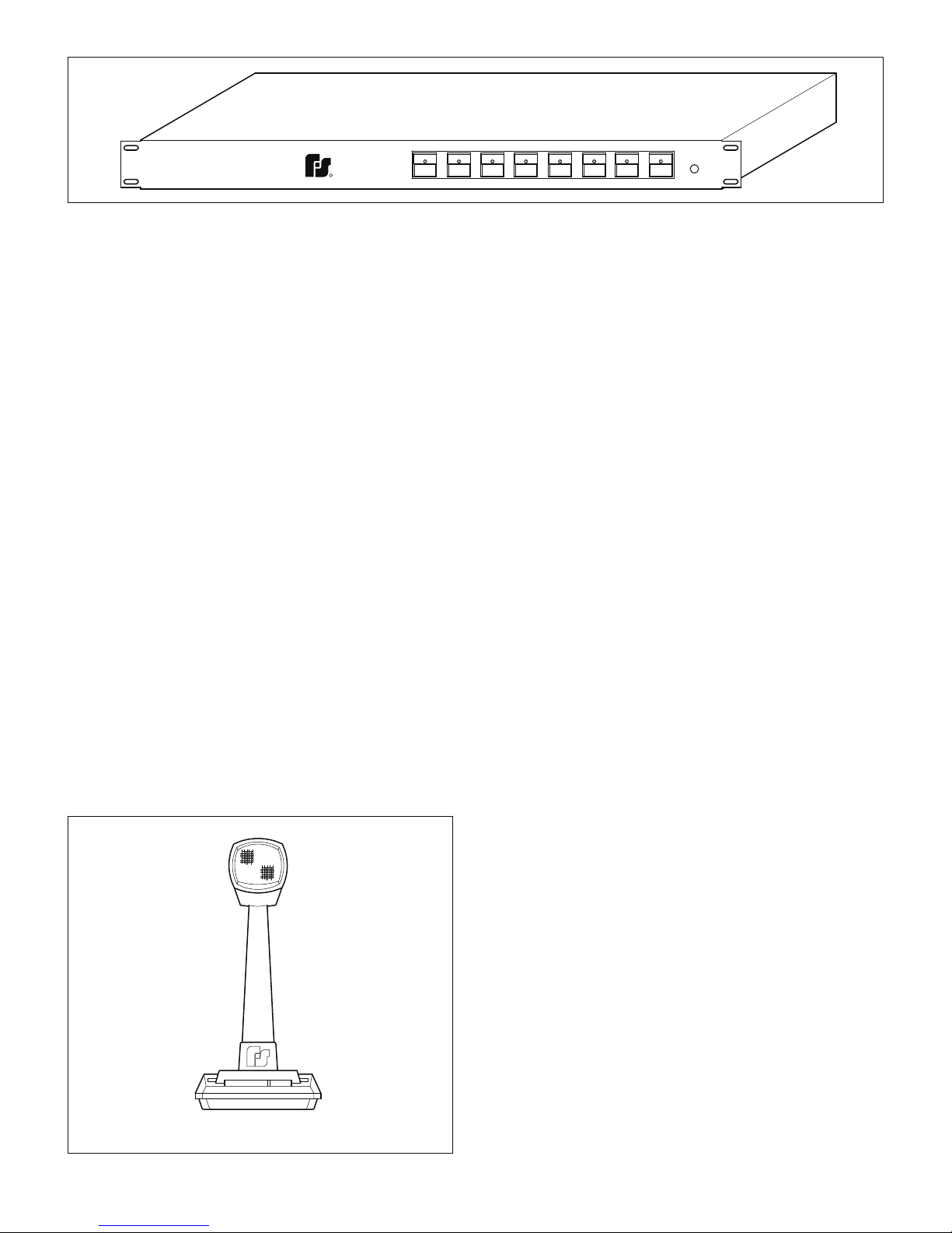
TheModelAR2000-M(seegure1-1)Audio
Router,isaULlistedandcULcertiedcentralcontrol
device that is capable of routing a selected audio input
tospeciczones.Itcancontrolsignalstospeakers
designed for 25Vrms line operation or 70Vrms line
operation. It can also control 1Vrms signals intended to
beampliedwithaseparateamplicationdevice.The
AR2000-Mhasapublicaddress(PA)functionsovoice
messages or instructions can be announced over the
AudioRoutersystemthroughanoptionalModelMSB-1
orMNC-1Microphone.Theunitcanalsobeusedtoplay
backgroundmusicgeneratedfromanexternalsource
over the Audio Router system.
TheModelAR2000-Misanaudiomultiplexing
device. It is capable of handling two inputs from any of
three different selected source voltages of 1, 25 or 70 volts.
Theunithas8selectablezoneswhicheithertheAortheB
sourceisroutedto.Thereisanallcallbuttonthatselects
allzones.Therearealso8programmablepresetsonthe
unit.Thepresetsareinitiatedbythefrontpanelbuttons
orbyremotecontactswiredtothebackpanel.Thefront
panelalsohasamonitorspeakerjack.Amicrophonejack
isalsoavailableforusewithaMSB-1.Themicrophonehas
priorityoverthetwousersuppliedsources.Thetelephone
featureisprotectedbyan8keypassword.Options
available allow changing the password and recording a
message for broadcasting. Commands entered via the
telephonekeypadallowtheusertosendamessage
tospeciedzones.Themicrophoneandthetelephone
interface have the same priority. If the microphone is in use,
the telephone interface is disabled. If the phone message
system is in use, the microphone is disabled.
If more than eight zones or eight presets are needed
bytheuser,aseparateAR2000-Z(SeeFigure1-2),
zoneunit,orAR2000-P(SeeFigure1-3),presetunitis
available.EachAR2000-ZorAR2000-Punitwilladdan
additional eight zone or preset controls respectively. Up to
sevenadditionalPresetorZoneunitsmaybeaddedfora
total of 64 zones and 64 presets.
TheModelMNC-1microphoneisahandheld,
noise canceling microphone that is ideal for use as a
localmicrophone.TheModelMSB-1microphone(See
Figure1-4)isabasestationtypemicrophonedesigned
fordesktopoperation.
TheModelAR2000-Mmaybeinstalledinindoor
installationsonlyasarackmounteddevice.
TheModelAR2000-Misarackmountunitthat
willtanystandard19"rackmountcabinet.TheModel
AR2000-Mcanbeusedforavarietyofprioritized
signalingpurposes,suchasplayingbackgroundmusic,
paging, start and dismissal, phone messaging and other
communication applications. Additional advantages of the
ModelAR2000-Mincludeeconomicalsystemexpansion
andlongtermsystemexibility.
TheModelAR2000-Mroutesaudiosignalsand
applies them through zone outputs to the devices in the
system.TheAR2000-MconnectseasilywithSelectone
ampliedspeakers.AModelAM25CKorAM70CK
ConnectorKitisrequiredineachSelectonedeviceto
connectittothesignalline.TheAudioRouterdevice
supplies 15W at either 25Vrms or 70Vrms. An additional
ampliermustbesuppliedtoobtainhigherwattage
levels.Caremustbetakentoensurethatthetotalline
impedance of all the connected devices does not cause
the line voltage to drop.

-2-
ZONE 1
PRESET 1
CH B
CH A
MICROPHONE
AUX SPEAKER
PHONE
AR2000-M
ALL CANCEL
ALL CALL
CORPORATION
UNIVERSITY PARK, IL U.S.A.
R
FEDERAL
SIGNAL
PRESET 7PRESET 4
ZONE 4ZONE 2 ZONE 3
PRESET 2 PRESET 3
ZONE 5 ZONE 6 ZONE 7
PRESET 6PRESET 5
POWER
ZONE 8
ALARM
PRESET 8
290A4120-01
Figure 1-1.
ZONE 2
AR2000-Z
UNIVERSITY PARK, IL U.S.A.
CORPORATION
FEDERAL
SIGNAL
R
ZONE 1 ZONE 5ZONE 4ZONE 3 ZONE 7ZONE 6 ZONE 8
POWER
290A4120-02
Figure 1-2.
Each preset can be manually activated locally with
its associated push button switch on the front panel or
with a contact closure at the associated preset control
inputonthebackpanel.Wheneverapresetisactivated,
either locally or remotely, its associated front panel push
buttonLEDilluminatestoindicatethatthepresethas
beenactivated.TheLEDremainslituntilthepresetis
deactivated or the remote contact closure is removed. As
an added feature, when a preset is remotely activated,
theassociatedLEDilluminatesandashesuntilthe
remotecontactclosureisremoved.AllAR2000-M
controls are located on the front panel except gain
adjustmentswhicharemadeonthebackpanelduring
installation.
Operation (normal mode)
PressingtheChannelAorChannelBbuttonwill
immediatelyswitchtheinputtothatchannel;thespeaker
indicatorlightswillindicatewhatspeakersareconnected.
Pushingaspeakerbuttonwillturnthatspeakeronor
off;pushingapresetbuttonwillselectspeakersper
thatpreset,andmayalsoselectChannelAorB(ifthat
presetwasconguredforaspecicchannel).Keyingthe
microphone while in this mode will cause the microphone
signaltobesenttotheselectedspeakers;releasing
themicrophonewillallowChannelAorBoperationto
resume.
KeyingtheMicrophonebuttonwillallowtheuserto
directaudiotospeciczones(defaultisAll-Call).Theuser
mayselectzonesusingeitherindividualspeakerorpreset
buttons;ChannelAorBoperationwillnotbeinterrupted
untilthemicrophoneisactuallykeyed.Releasing
themicrophonewillallowChannelAorBtoresume
operationonitsselectedspeakers.
Pressing the All Call button (whether the unit is in
MicrophonemodeorChannelA/Bmode)willcauseall
zones to be selected. Pressing any individual zone when All
Call is lit, however, will cancel all the zones except that one.
Pressing All Call will perform the following function:
If all of the zones are not selected, “All Call” will
select all 64 zones. Otherwise, pressing “All Call” will
cancel all of the zones.
Telephone operation
When the line attached to the Router is called,
therouterwillanswerwiththeMessage“ENTER
PASSWORD”.Thecallerisrequiredtoentertheir8digit
password.Thecallerisgiven2chancestoenterthe
correct password.
If the correct password is not entered, the caller
hearsthemessage“GOODBYE”andthesystemhangs
up the phone line.
If the correct password is entered the caller will
hearthemessage“PRESS9KEYTOCHANGETHE
PASSWORDOR6KEYTORECORDAMESSAGE”.
Ifthecallerpressesthe9key,themessage“ENTER
NEWPASSWORD”willinformthecallertoenteranew
password.Thesamenewpasswordmustbeentered
twice. Otherwise, the caller will hear the message
“PASSWORDNOTCHANGED”thenthemessage
“GOODBYE”andthesystemhangsupthephoneline.If
the new password is successfully entered twice, the caller
willhearthemessage“PASSWORDCHANGED”then
themessage“GOODBYE”andthesystemhangsupthe
phone line.

-3-
PRESET 2
AR2000-P
UNIVERSITY PARK, IL U.S.A.
CORPORATION
FEDERAL
SIGNAL
R
PRESET 1 PRESET 5PRESET 4PRESET 3 PRESET 7PRESET 6 PRESET 8
POWER
290A4120-03
Figure 1-3.
Ifthecallerpressesthe6key,themessage
“RECORDMESSAGE,PRESS#KEYTOBROADCAST
YOURMESSAGE”promptsthecallertostartspeaking.
Themessagecanbeupto90secondslong.Iftheuser
exceeds 90 second duration, the message will not play
back.
Atanytimeduringthecall,thecallercanenterthe#
keyorhang-upthephonetoexit.Also,whenakeyinput
isnecessary,thecallerhas5secondstoenterakeyor
the system hangs up automatically.
Thepasswordcanbereturnedtothedefault
“12345678”byopeningthecoveroftheRouterand
settingswitchSW1position#4tothe“ON”positionfor
5 seconds with the power “ON”.
Defaultistoallzones.Phonereceivingisdisabled
duringmessageplayback;therefore,subsequentcalls
must wait for the current message to be completed
beforeanotherrecordingwilltakeplace.
Preset operation
Thepresetoptosareacombinationofedgeand
level-tripped.Ifthesystemseesanactiveedgeon
an opto, it will set the input and output relays for the
correspondingpreset.Therelayswillremainsetuntilthe
input goes away.
Setting a Preset:
Tosetapreset,selectthezonesdesiredfor
the preset by pressing and releasing the appropriate
zonebutton.TheLEDcorrespondingtothatzonewill
illuminate. Select the input source (Channel A or Channel
B)forthatpreset.Pressandholdtheappropriatepreset
buttonuntilitbeginstoash.Thepresetisnowset.
Torecallapresetsimplyselectthepresetby
pressing and releasing the associated preset button.
1-2. CHASSIS DESCRIPTION.
TheModelAR2000-Misassembledinablack,
sprayedaluminum3-piecehousingapproximately17.5”
wideby14.25"deepby3.5"high.Itisintendedtobe
rackmountedinastandard19”rackmountcabinet.
Thehousingisheldtogetherwitheighteenscrews,
eight on the front panel, six on the rear panel and four
securing the top to the sides.
Themainprintedcircuitboardisattachedtothe
lower housing with seven screws. Separate wiring
harnesses connect the front and rear boards to the
mainprintedcircuitboard.Thefrontpanelswitchesare
designatedasCHA,CHB,ALLCALL,CANCELZONE1
throughZONE8andPRESET1throughPRESET8.
TheModelAR2000-Pisassembledinablack,
sprayedaluminum3-piecehousingapproximately17.5”
wideby10.125"deepby1.75"high.Itisintendedtobe
rackmountedinastandard19”rackmountcabinet.The
housing is held together with twelve screws, four on the
front panel, four on the rear panel and four securing the
toptothesides.Thefrontpanelswitchesaredesignated
asPRESET1throughPRESET8.
TheModelAR2000-Zisassembledinablack,
sprayedaluminum3-piecehousingapproximately17.5”
wideby10.125"deepby1.75"high.Itisintendedtobe
rackmountedinastandard19”rackmountcabinet.The
housing is held together with twelve screws, four on the
front panel, four on the rear panel and four securing the
toptothesides.Thefrontpanelswitchesaredesignated
asZONE1throughZONE8.
290A4120-04
Figure 1-4.

-4-
1-3. CONTROL CIRCUITRY.
A. Control Circuitry.
ThecontrolcircuitryintheAR2000-Mhasabuilt-
inprioritylevelfeature.Thelocalmicrophonehasthe
highest priority level when activated. If a preset is initiated
bycontactclosure,theAR2000-Mwillgrantthatpreset
priority.TheAudioRouterwillstorethecurrentselection
rst,thenactivatethepreset.Oncethecontactclosure
isremoved,theAR2000-Mwillreturnthesystemtothe
previous condition. Pressing cancel will deactivate any
currently active selections.
B. All CALL Pushbutton.
TheALLCALLpushbuttonswitchselectsand
connects all zones to the currently selected input source.
Pressing the ALL CALL again returns the system to the
previous condition.
C. CANCEL Pushbutton.
TheCANCELpushbuttonwhenpressedwillreset
all the manually activated signaling functions of the
AR2000-M.
D. MONITOR SPKR.
Amonitorspeakermaybeconnectedtotheunit
at this output. Audio to this output will exist during all
conditionsexceptwhenthemicrophoneisinuse.This
preventsanyfeedbackfromthemicrophone.
E. ADDITIONAL ZONES.
AnAR2000-Zmaybeconnectedtoaddon
additional8zonesofcontrol.Ifdesired,uptoseven(7)
totalAR2000-Zunitsmaybeaddedtoprovideatotalof
64 zones.
F. ADDITIONAL PRESETS.
AnAR2000-Pmaybeconnectedtoaddon
additional8presetsofcontrol.Ifdesired,uptoseven(7)
totalAR2000-Punitsmaybeaddedtoprovideatotalof
64 presets.
1-4. POWER.
WARNING
InordertopreventpowertotheAR2000-Mfrom
being accidentally turned off, the unit has a power
switchlocatedonthebackoftheunit.Before
performing any installation or maintenance,
ensure that power is disconnected.
ThefrontpanelhasagreenLEDtoindicatethe
presenceofprimarypower.ItalsohasaredLEDto
indicatethepresenceofsecondarypowerinuse.The
AR2000-Mcanbeoperatedfromeithera120VAC,
240VACora24VDCpowersource.TheACpoweris
connected via the power cord, which requires manual
switchinginordertooperate.24VDCBackupconnects
viatherearterminalsdirectlyunderneaththe4-Amp,
Bussman-typeGMTindicatingfuse.
WARNING
Ifthisunitistobeconnectedtoanon-power
limited 24 volt dc supply, the National Electrical
Code (NFPA 70) requires that those leads be
separated from other classes of wiring connected
to this unit.
TheAR2000-PandtheAR2000-Zobtainpower
directlyfromtheAR2000-M.
1-5. AUDIO INPUTS.
ChannelAandChannelBinputsareprovidedin
thebackoftheunittocouplestandard1voltaudio
signalfromabackgroundmusicsourcesuchasaradio
receiver,CDplayeroratapeplayer.Theinputscanalso
be selected to accept a 25Vrms or 70Vrms input source.
TheChannelAinputisselectablefromthefrontpanelby
depressingtheChannelAselectionbutton.Toselectthe
ChannelBinput,depresstheChannelBselectionbutton
onthefrontpanel.OnlyChannelAorChannelBmaybe
activated at one time. It is not possible to activate both
ChannelAandChannelBaudiosourcessimultaneously.
1-6. MICROPHONE INPUT OPTION.
AFederalSignalModelMSB-1microphonecanbe
connecteddirectlytotheAR2000-Mviathemodularjack
provided on the front of the unit (highest priority).
1-7. TELEPHONE INPUT OPTION.
A standard telephone line can be connected directly
totheAR2000-Mviathemodularphonejackprovidedat
thebackoftheunit.Thisallowstheusertocontactthe
AR2000-Mviaphone,recordamessageanddeliveritto
zones selected by the phone line user.

-5-
1-8. ELECTRICAL DETAILS.
Termination:Screwterminalsfor13AWGto
23 AWG conductors.
Voltage Range: Selectable 120 VAC
or240VAC50/60Hz.
Batterybackup: 24VDC
Channel A input: Selectable to be 1 Vrms, 25 Vrms,
or 70 Vrms
ChannelBinput: Selectabletobe1Vrms,25Vrms,
or 70 Vrms
OnboardAmplier: 15Wattsmaximum
Amplier
Output Voltage: Selectable to be 1 Vrms, 25 Vrms,
or 70 Vrms
Frequencyrange: -3dB@150Hz -3dB@12kHz
(noload) -6dB@85Hz -6dB@24.8kHz
MonitorSpeaker
output: 300mWtypical@1kHz,8ohm
Maximumswitching
currentforeachzone:15AMPS
II. SPECIFICATIONS.
2-1. AR2000-M POWER INPUT.
InputVoltage 120V,50-60HZ
Standby Current 350 mA
Operating Current 2 A
Power Consumption 240 Watts
InputVoltage 240V,50-60HZ
Standby Current 160 mA
Operating Current 1 A
Power Consumption 160 Watts
2-2. EMERGENCY POWER SOURCE INPUT.
InputVoltage 24VDC
Standby Current 650 mA
Operating Current 4 A
2-3. AUDIO INPUT.
A.LocalPA(UseoptionalModelMSB-1microphone)
InputImpedance 5kOhms
InputVoltage 16mVrms(MAX)
B.ChannelA/ChannelB
InputImpedance 28.87Kohms@1Vrmsposition
22.67Kohms@25Vrmsposition
22.10Kohms@70Vrmsposition
Input Voltage Selectable at 1Vrms,
25Vrms or 70Vrms
2-4. AUDIO OUTPUTS.
A. Output Impedance
BalancedSig.line 27Ohms
B.OutputVoltageLevelsnoLoad
BalancedSignalLine@70Voltposition 70Vrms
BalancedSignalLine@25Voltposition 25Vrms
BalancedSignalLine@1Voltposition 1-20Vrms
2-5. REMOTE PRESET ACTIVATION CIRCUIT.
NOTE:Itisrecommendedthattheinstalleruseshielded,
twisted pair wire in order to minimize any false activation
due to environmental noise.
Type DryContactClosure
LineImpedance 1Kohm(MAX)
CircuitCurrent 20mAMax(12VDC)
2-6. REMOTE MIC. ACTIVATION CIRCUIT (PTT).
Type DryContactClosure
LineImpedance 100Ohm(MAX)
CircuitCurrent 10MAMax(12VDC)
2-7. RELAY CONTACT CLOSURE OUTPUTS.
Relays
Type: DryContactClosure
Rating: 15A maximum current per zone
2-8. FUSE.
F1 TypeGMC2A,250V
F2 Bussman-typeGMT4A
2-9. PHYSICAL.
A.AR2000-M
Weight 16lb8oz.(7.5kg.)
Dimensions(HWD) 3.5"x173/8"x14.25"
89mmx442mmx362mm
CaseMaterial 14GAAluminum
B.AR2000-P
Weight 3lb,15oz.(1.8kg)
Dimensions(HWD) 1.75"x173/8”x10.125"
44.5mm x 442mm x 257mm
CaseMaterial 14GAAluminum
C.AR2000-P
Weight 3lb,15oz.(1.8kg)
Dimensions(HWD) 1.75"x173/8”x10.125"
44.5mm x 442mm x 257mm
CaseMaterial 14GAAluminum

-6-
2-10. AGENCY APPROVALS.
A.ULANDcULCertications.
UL813,(AZJX)CommercialAudioandRadio
Equipment, Systems and accessories
C22.2No.1-98,(AZJX7)Audio,Video,andSimilar
Electronic Equipment
B.CSACertication-Pending
C22.2No.1-98,Audio,Video,andSimilarElectronic
Equipment
C. FCC.
ThisdevicecomplieswithPart15oftheFCCRules.
Operation is subject to the following
two conditions: (1) this device may not cause harmful
interference, and (2) this device
must accept any interference received, including
interference that may cause undesired operation.
III. INSTALLATION.
SAFETY MESSAGE TO INSTALLERS
Peoples lives depend on proper installation of our
products. It is important to follow all instructions shipped
withtheseproducts.Thesedevicesaretobeinstalled
byaqualiedelectricianinaccordancewiththeNational
Electrical Code (NFPA 70), or other national or local
codes, under the direction of the local authority having
jurisdiction.
Theselectionofthemountinglocationforthe
device, its controls and routing of the wiring is to be
accomplished under the direction of the Facilities
Engineer and the Safety Engineer. In addition, listed
below are some other important safety instructions and
precautions you should follow:
• Readandunderstandallinstructionsbefore
installing or operating this equipment.
• Donotconnectthisunittothesystemwhen
power is on.
• Speakersconnectedtothissystemcanproduce
loud sounds which may cause, in certain
situations,permanenthearingloss.Youshould
takeappropriateprecautionssuchaswearing
hearing protection.
• Afterinstallation,testtheAudioRoutersound
system to ensure proper operation.
• ShowtheseinstructionstoyourSafetyEngineer
andthenletheminasafeplaceandreferto
themwhenmaintainingand/orreinstallingthe
unit.
• Establishaproceduretoroutinelycheck
the sound system for proper activation and
operation.
• Consulttheauthorityhavingjurisdictioninyour
area regarding the proper use and installation of
this product.
3-1. UNPACKING.
Afterunpackingtheunit,examineitfordamage
that may have occurred in transit. If equipment has been
damaged, do not attempt to install or operate it. File a
claim immediately with the carrier stating the extent of the
damage.Carefullycheckallenvelopes,shippinglabels
and tags before removing or destroying them.
3-2. MOUNTING ARRANGEMENTS.
TheAR2000-Mprovidesfour(4)holesformounting
inastandardrack.Itutilizesaspaceof2U.
TheAR2000-Pprovidesfour(4)holesformounting
inastandardrack.Itutilizesaspaceof1U.
TheAR2000-Zprovidesfour(4)holesformounting
inastandardrack.Itutilizesaspaceof1U.
3-3. ELECTRICAL CONNECTIONS.
DANGER
Toavoidelectricalshockanddamagetothe
device, do not attempt to connect wires when
power is on.
TerminalblocksaresuppliedontheAR2000-M
foreldwiring.Strip1/2"ofinsulationfromthewiring
leads. Attach the appropriate wires to the corresponding
terminals.Tightenthescrewstoinsurethatthewiresare
rmlyheldinplace.Theterminalswillacceptconductor
sizes 23 AWG to 13 AWG.
3-4. SIGNAL LINES.
A.Thesignallinestransferthetonesignalsand
verbalmessagesfromtheAR2000-Mtotheselected
zones and their devices. In order to reduce the possibility
ofcrosstalk,humandstaticnoisepick-up,thesignal
lines must be twisted pair, shielded audio cable. Although
themajorityofsystemsuseAWG18shieldedtwisted
pair audio cables, the size of the audio cable should be
adjusted to correspond to the level of audio being routed
in your application.

-7-
CAUTION
If too small a wire gauge is used, unacceptable
signal voltage drop in the signal line will cause
reduced sound output from the remote signal
device. Only use a cable having wire gauge
greater than 22AWG.
B. Federal does not recommend that new or
existingtelephonelinesbeusedassignallinesin
anAudioRoutersystemforthefollowingreasons:
1. Interference from other services or systems, or
interference from the system to other services.
2. Crosstalk,interferenceorhuminducedbyother
telephone lines.
3. Extended downtime because of the second party
involvement required to service the lines.
4. Theadditionalcostofinstallation,interfacingdevices
andmonthlychargesasopposedtoaone-timecost
of performing the installation.
3-5. MODEL AR2000-M SIGNAL CONNECTIONS.
CAUTION
Crosstalkcanoccurbetweensignallinesand
power lines, causing confusing messages, which
interfere with the capability of this equipment.
Donotinstallsignallinesinthesameconduitwith
power lines. Avoid routing signal lines on cable
trays with high voltage power lines.
Toconnectthesignallinesofthesystemtothe
AR2000-M,connectacolor-codedshieldedtwistedpair
ofaudiocableshavingconductorsnosmallerthan18
AWGto+and-ofeachzoneoutputbeingutilizedto
theappropriateremotedevice(s).(Seegure3-1.)Every
remote signaling device in the system will be connected
in parallel to these lines. When connecting the remote
devices in parallel to the signal lines, observe the correct
polarity and install wire nuts over the connections.
NOTE:Ifusingthesuppliedamplieroranexternal
amplier,theoutputaudiomustbeconnectedusing
appropriatewirefromAUDIOOUTtoAUDIOINFROM
EXTERNALAMP.Ifusingtheon-boardamplier,directly
connecttheAUDIOINFROMEXTERNALAMPtothe
AUDIOOUTterminalsonthebackoftheAR2000-M.See
section3-4forrecommendedwiresizes.
3-6. CONNECTION TO REMOTE DEVICES.
Physically install the remote device(s); follow the
installationinstructionspackedwiththedevice.
A. 300GC, 300GCX, 300X, 302GC, 302GCX,
302X, 50GC, and 50GCB.
Toconnectthesemodelstoa25Vrmsor70Vrms
signalline,aModelAM25CKorAM70CKconnectorcard
mustbeused.Seegure3-1andinstructionsbelowfor
the appropriate signal line voltage.
B. 70VrmsSignalLineApplication.
TheAR2000-Mhasprovisionforconnecting70
Vrmslineoperatedspeakerstoitsoutput.Connect
the70VrmslineattheterminalsofZone1–Zone8
terminalblock(s).Connectthespeakersinparalleltothis
lineusing70Vrmslinetap.Thisoutputisselectedby
settingtheswitchonthebackoftheAR2000-Mtothe
70Vrmsposition.Theoutputaudiomustbeconnected
using16GAwirefromAUDIOOUTtoAUDIOINFROM
EXTERNALAMP.TheGainmaybeadjustedusingthe
AUDIOOUTVOLUMEcontrolknob.
C. 25VrmsSignalLineApplication.
TheAR2000-Mhasprovisionforconnecting
25Vrmslineoperatedspeakerstoitsoutput.Connect
the25VrmslineattheterminalsofZone1–Zone8
terminalblock(s).Connectthespeakersinparalleltothis
lineusing25Vrmslinetap.Thisoutputisselectedby
settingtheswitchonthebackoftheAR2000-Mtothe
25Vrmsposition.Theoutputaudiomustbeconnected
using16GAwirefromAUDIOOUTtoAUDIOINFROM
EXTERNALAMP.TheGainmaybeadjustedusingthe
AUDIOOUTVOLUMEcontrolknob.
D. Low Level Audio Output.
TheAR2000-Malsohasprovisionfor1voltaudio
output that can be switched to each zone for individual
externalamplication.Thislowleveloutputisavailable
atthesameterminalsasinBandCabove.Thisoutput
isselectedbysettingtheswitchonthebackofthe
AR2000-Mtothe1Vrmsposition.Theoutputaudiomust
alsobeconnectedusing18-20GAwirefromAUDIOOUT
toAUDIOINFROMEXTERNALAMP.TheGainmaybe
adjustedusingtheAUDIOOUTVOLUMEcontrolknob.It
canalsobeconnectedtoananalogberoptictransmitter
sothataudiocanbetransmittedoveraberopticlinkin
an electrically noisy environment.
E. ExternalAmplierConnectionforAlternate
Power Audio Output.
TheAR2000-Malsohasprovisiontoconnectan
externalamplier,suchastheFederalSignalHP440,to
be switched to the corresponding zones. Set the Audio
RouterupaslistedinDabove.Connectthe1voltAUDIO
OUTtotheaudioinputofanotheramplier.Theoutput
audio must be connected using appropriate wire gauge
fortheapplicationtotheAUDIOINFROMEXTERNAL
AMP(Seegure3-2.)TheGainmaybeadjustedusing
theAUDIOOUTVOLUMEcontrolknob.
CAUTION
Carefulattentionshouldbepaidinordertomake
sure orientation of the signal is not reversed.

-8-
3-7. POWER CONNECTIONS.
Thetwobasicmethodsofsupplyingpowertoan
AudioRouterdeviceare120VAC50/60HzLocalPower
or240VAC50/60HzLocalPowerand24VDCBackup
Power.Thefollowingparagraphsdescribeeachmethod
along with the advantages and disadvantages of each.
LOW (-) WHT
HI (+) WHT
AM25CK
SIGNAL LINES
SHIELDED
TWISTED PAIR
SIGNAL LINES
SHIELDED
TWISTED PAIR
300GC
MODEL AR2000-M WITH MODEL 300GC
CONNECTIONS USING INTERNAL AMPLIFIER
AM25CK
120VAC 120VAC
AM25CK
120VAC
AM25CK
120VAC
AM25CK
300GC 300GC 300GC 300GC
120VAC
AM25CK
120VAC
AM25CK
120VAC120VAC
AM25CK
300GC 300GC 300GC
290A4120-05B
AUDIO OUT
PRESET 7
DRY CONTACT IN (N.O.)
+
ALARM
INDICATOR
-
- +
ZONE 3
PRESET 3
DRY CONTACT IN (N.O.)
- +
ZONE 1
PRESET 1
GND +24V
POWER OUT
TO PRESET
ABOVE
GND +24V
- +
ZONE 2
AUDIO OUT
PRESET 2
- +
ZONE 4
PRESET 4
- +
ZONE 5
- +
ZONE 6
PRESET 5 PRESET 6
- +
CH B INPUT
CH B INPUT
VOLUME
MICROPHONE
VOLUME
AUDIO IN FROM EXTERNAL AMP
OR FROM AUDIO OUT 15W
- +
ZONE 7
- +
ZONE 8
PRESET 8
AUDIO OUT
TO BELOW
- +
- +
ALL CALL
OPTO
COMMON +24V
AUDIO OUT
CONTROL OUT
TO ZONE
PHONE LINE
NUMBER
( )
25Vrms
AUDIO OUT(15W)
70Vrms
- +
AUDIO OUT
1Vrms
25V
rms
70V
rms
1V
rms
25V
rms
70V
rms
1V
rms
SELECT
VOLUME
CONTROL IN
FROM PRESET PHONE
VOLUME
CH B
- +
CH A INPUT
SELECT
CH A INPUT
VOLUME
SELECT
CH A
MONITOR
SPEAKER
VOLUME
(CLASS 2) POWER
OUT TO AR2000-P
(CLASS 2)
POWER OUT
TO AR2000-Z
CAUTION: TO REDUCE
THE RISK OF FIRE,
REPLACE ONLY WITH
BUSS 250V, 4A GMT FUSE
(CLASS 2)24VDC
BACKUP POWER
120 VAC, 50/60 HZ, 2A
240 VAC, 50/60 HZ, 1A
CAUTION: TO REDUCE THE RISK OF FIRE,
REPLACE ONLY WITH GMC 2A, 250V FUSE
WARNING:
NO USER-SERVICEABLE PARTS INSIDE. REFER SERVICING TO
QUALIFIED PERSONNEL. TO REDUCE THE RISK OF FIRE OR ELECTRICAL SHOCK,
DO NOT REMOVE COVER OR EXPOSE THIS APPLIANCE TO RAIN OR MOISTURE.
Figure 3-1.
A.LocalPower(seegure3-3).
In this system, power is supplied to the
AR2000-Mdevicebyconnectingittoa120VACor
240VAC supply in the immediate vicinity of the device. An
input selector switch is provided and must be set to the
appropriate input voltage prior to turning the device on.
AUDIO OUT
PRESET 7
DRY CONTACT IN (N.O.)
+
ALARM
INDICATOR
-
- +
ZONE 3
PRESET 3
DRY CONTACT IN (N.O.)
- +
ZONE 1
PRESET 1
GND +24V
POWER OUT
TO PRESET
ABOVE
GND +24V
- +
ZONE 2
AUDIO OUT
PRESET 2
- +
ZONE 4
PRESET 4
- +
ZONE 5
- +
ZONE 6
PRESET 5 PRESET 6
- +
CH B INPUT
CH B INPUT
VOLUME
MICROPHONE
VOLUME
AUDIO IN FROM EXTERNAL AMP
OR FROM AUDIO OUT 15W
- +
ZONE 7
- +
ZONE 8
PRESET 8
AUDIO OUT
TO BELOW
- +
- +
ALL CALL
OPTO
COMMON +24V
AUDIO OUT
CONTROL OUT
TO ZONE
PHONE LINE
NUMBER
( )
25Vrms
AUDIO OUT(15W)
70Vrms
- +
AUDIO OUT
1Vrms
25V
rms
70V
rms
1V
rms
25V
rms
70V
rms
1V
rms
SELECT
VOLUME
CONTROL IN
FROM PRESET PHONE
VOLUME
CH B
- +
CH A INPUT
SELECT
CH A INPUT
VOLUME
SELECT
CH A
MONITOR
SPEAKER
VOLUME
(CLASS 2) POWER
OUT TO AR2000-P
(CLASS 2)
POWER OUT
TO AR2000-Z
CAUTION: TO REDUCE
THE RISK OF FIRE,
REPLACE ONLY WITH
BUSS 250V, 4A GMT FUSE
(CLASS 2)24VDC
BACKUP POWER
120 VAC, 50/60 HZ, 2A
240 VAC, 50/60 HZ, 1A
CAUTION: TO REDUCE THE RISK OF FIRE,
REPLACE ONLY WITH GMC 2A, 250V FUSE
WARNING:
NO USER-SERVICEABLE PARTS INSIDE. REFER SERVICING TO
QUALIFIED PERSONNEL. TO REDUCE THE RISK OF FIRE OR ELECTRICAL SHOCK,
DO NOT REMOVE COVER OR EXPOSE THIS APPLIANCE TO RAIN OR MOISTURE.
LOW (-) WHT
HI (+) WHT
AM25CK
SIGNAL LINES
SHIELDED
TWISTED PAIR
300GC
MODEL AR2000-M WITH MODEL 300GC
CONNECTIONS USING EXTERNAL AMPLIFIER
AM25CK
120VAC 120VAC
AM25CK
120VAC
AM25CK
120VAC
AM25CK
300GC 300GC 300GC 300GC
120VAC
AM25CK
120VAC
AM25CK
120VAC120VAC
AM25CK
300GC 300GC 300GC
290A4120-06B
HP440
AMP
OUTPUT
AMP
INPUT
Figure 3-2.

-9-
290A4120-07B
+
-
24VDC
BACKUP POWER
PS600
TO 120VAC
AUDIO OUT
PRESET 7
DRY CONTACT IN (N.O.)
+
ALARM
INDICATOR
-
- +
ZONE 3
PRESET 3
DRY CONTACT IN (N.O.)
- +
ZONE 1
PRESET 1
GND +24V
POWER OUT
TO PRESET
ABOVE
GND +24V
- +
ZONE 2
AUDIO OUT
PRESET 2
- +
ZONE 4
PRESET 4
- +
ZONE 5
- +
ZONE 6
PRESET 5 PRESET 6
- +
CH B INPUT
CH B INPUT
VOLUME
MICROPHONE
VOLUME
AUDIO IN FROM EXTERNAL AMP
OR FROM AUDIO OUT 15W
- +
ZONE 7
- +
ZONE 8
PRESET 8
AUDIO OUT
TO BELOW
- +
- +
ALL CALL
OPTO
COMMON +24V
AUDIO OUT
CONTROL OUT
TO ZONE
PHONE LINE
NUMBER
( )
25Vrms
AUDIO OUT (15W)
70Vrms
- +
AUDIO OUT
1Vrms
25V
rms
70V
rms
1V
rms
25V
rms
70V
rms
1V
rms
SELECT
VOLUME
CONTROL IN
FROM PRESET PHONE
VOLUME
CH B
- +
CH A INPUT
SELECT
CH A INPUT
VOLUME
SELECT
CH A
MONITOR
SPEAKER
VOLUME
(CLASS 2) POWER
OUT TO AR2000-P
(CLASS 2)
POWER OUT
TO AR2000-Z
CAUTION: TO REDUCE
THE RISK OF FIRE,
REPLACE ONLY WITH
BUSS 250V, 4A GMT FUSE
(CLASS 2)24VDC
BACKUP POWER
120 VAC, 50/60 HZ, 2A
240 VAC, 50/60 HZ, 1A
CAUTION: TO REDUCE THE RISK OF FIRE,
REPLACE ONLY WITH GMC 2A, 250V FUSE
WARNING:
NO USER-SERVICEABLE PARTS INSIDE. REFER SERVICING TO
QUALIFIED PERSONNEL. TO REDUCE THE RISK OF FIRE OR ELECTRICAL SHOCK,
DO NOT REMOVE COVER OR EXPOSE THIS APPLIANCE TO RAIN OR MOISTURE.
Figure 3-3.
CAUTION
Improper installation could render this system
inoperable, interfering with the indicating nature
ofthisproduct.Theinstallationmustconformto
applicablelocaland/orNationalElectricalcodes.
Ifanemergencypowersourceisrequired,abackup
power system described below should be employed.
WARNING
IftheAR2000-Mistobeconnectedtoanon-
power limited 24 volt dc supply, the National
Electrical Code (NFPA70) requires that those
leads be separated from other classes of wiring
connected to this unit.
B.BackupPower(Seegure3-3).
1. General.
Inthebackuppowersystemallofthelocalpowerlines
are connected in parallel to one centrally located power
sourceof24VDC.
2.AdvantagesoftheBackupPowerSystem.
a. Theentiresystemmaybeindependentoflocalline
voltage.
b. Theentiresystemcanbeswitchedtoanemergency
standby power source in the event of a power failure.
c. Thecentralpowersystemhastheaddedadvantage
that an auxiliary power supply, such as the Federal
ModelPS600canbeusedtopowerthelocal
AudioRouterDevice.IfthePS600isused,itisnot
necessary to switch the power source if a power
failure occurs.
3.DisadvantagesofBackupPowerSystem.
a. A separate power source for all remote devices is
required. Heavy power lines are required from that
power source to the remote devices in the system.
Thesizeofthepowerlinesisdependentuponthe
numberofampliersandthetotaldistanceofthe
power loop in order to minimize the voltage drop while
a signal is being routed.
b. Future expansion is limited by the current capacity
of the power source and the power lines that were
initially installed.
c. Central power installations must comply with local
electricalcodes.MostpowercircuitsareClassI
circuits.Therefore,conduitwillprobablyberequired.
Installation costs are higher than a local power
system.
C. AR2000-M System Power Connections.
DANGER
Installation with the system power on could
causeseriousinjuryordeath.Donotperform
any installation or maintenance on this system
when power is on. Ensure that the power is
disconnected before proceeding.
WARNING
Thisdeviceistobeinstalledbyatrained
electrician who is thoroughly familiar with the
national electrical code (NFPA 70) and local
codes and will follow the guidelines.

-10-
WARNING
Ifthisunitistobeconnectedtoanon-power
limited 24 volt dc supply, the National Electrical
Code (NFPA70) requires that those leads be
separated from other classes of wiring connected
to this unit.
CAUTION
Crosstalk,interference,orhumcanbeinduced
in signal lines, causing poor audio output or
confusing messages, which interferes with the
capabilityofthisequipment.Donotinstallpower
lines in the same conduit as signal lines.
OperatingpowerisconnectedtoAR2000-M
by merely inserting the plug end of the line cord into any
standard120volt,60Hzoutlet.TheAR2000-Misfactory
setfor120VAC50/60Hzoperation.If240voltoperation
ispreferred,theinputblockprovidesaswitchthatmust
be set to this position in order to function at 240VAC
operation.
Ifitisdesiredtouse24VDCeitherasaprimary
or auxiliary source of power, connect the “+” terminal of
24voltDCpowersupplytothe“+”terminalatthe24VDC
BACKUPPOWERterminalontheAR2000-Mand“-”
terminalofthe24VDCpowersupplytothe“-“terminalat
the24VDCBACKUPPOWERterminalontheAR2000-M
locatedinthebackofthedevice.(Seegure3-3.)
D. AR2000-P and AR2000-Z Power
Connections.
OperatingpowerisconnectedtoAR2000-P
andAR2000-Zbymerelyconnecting24VDCfromthe
AR2000-Mtoeachunit.Aterminalblockisprovided
attherear-leftsideofeachunitforpowerconnection.
Observe and maintain proper polarity when wiring the
power to these units. Connect the “+” terminal of the
AR2000-Mtothe“+”terminaloftheAR2000-Patthe
“+”terminallocatedinthebackofdevice.Connectthe
“-”terminaloftheAR2000-Mtothe“-”terminalofthe
AR2000-Patthe“-”terminallocatedinthebackof
device.Anadditional24VDCpoweroutletisprovidedon
eachAR2000-PandAR2000-Zfordaisy-chainingthe
powertoeachsub-unit.RepeatforeachAR2000-Pand
AR2000-Z.
SetupfortheAR2000-Ppresetsisdoneinthe
samewayastheAR2000-Mpresets. (Seegure3-4.)
SetupfortheAR2000-Zzonesisdoneinthe
samewayastheAR2000-M.Anaudioinputisprovided
on each unit to be routed to each of the zones it selects.
Thisaudioshouldbeconnectedbywiringaconnection
from the master audio output to the provided input
terminals.(Seegure3-5.)EachadditionalAR2000-Z
should obtain audio in the same manner from the unit
above.(Seegure3-5.)
3-8. CONNECTIONS TO REMOTE SWITCHES.
TheAR2000-Mpresetscanbeactivatedremotely
by any normally open low current switch contacts
having a current capacity of at least 50 mA inductive.
Figure3-6illustratestheconnectionofswitchcontacts
totheAR2000-M.S1,S2,S3andS4representsremote
switchcontactssuchasthosefoundinowswitches,
programclocks,heatdetectors,andsmokedetectors.
Theremotelyactivatedpresetsfunctionaslongasthe
activating contacts remain closed. A jumper needs to be
placedacrossOPTOCOMMONandtheprovided+24V
terminalnexttoitonthebackoftheAR2000-Minorder
for the remotely activated presets to function. A remote
switch may be connected to the ALL CALL position if
desired.TheseareallNormallyOpencontactsthatinitiate
with contact closure and remain active until the contact is
opened again.
3-9. INPUT SOURCE CONNECTIONS.
WARNING
InstallationormaintenanceonAR2000-Mwhen
power is on can result in serious injury or death.
Donotperformanyinstallationormaintenanceto
the system when power is on.
Set selector for CH A to the appropriate input
voltage, 1Vrms, 25Vrms or 70Vrms. Connect the “+”
of the source device to the “+” terminal at the Channel
Ainput.Connectthe“-“ofthesourcedevicetothe“-“
terminal at the Channel A input. Repeat this process for
theChannelBinput.CHAandCHBvolumecontrolsare
available just above each input selector to allow the input
gain to be adjusted.
CAUTION
Becertaintosettheinputselectorswitchtothe
appropriate input voltage to avoid damage to the
unit and the device being connected.
3-10. COMMUNICATION CONNECTIONS for
AR2000-P and AR2000-Z.
WARNING
It is important that the communication lines
be properly connected to their respective
communication port. Failure to connect the
cables properly will damage the devices and
possibly render them inoperable.
Thelabelonthebackofeachdeviceindicates
wherethecommunicationcablelinkshouldbe
connected.Seegure3-6forappropriateplacement.

-11-
A.ConnectingaModelAR2000-Z.
Usingtheprovided8positionmodularcable,
connect the bottom communication port of the
AR2000-MtothetopportoftheAR2000-Z.(Seesection
3-7partDforanexplanationofthepowerconnectionto
this unit.)
B.ConnectingaModelAR2000-P.
Usingtheprovided8-positionmodular
cable, connect the top communication port of the
AR2000-MtothebottomportoftheAR2000-P.(Refer
toparagraph3-7.D.foranexplanationofthepower
connection to this unit.)
3-11. TYPICAL CONNECTION EXAMPLES
A.ConnectingaCDPlayertotheAudioRouter.
DisconnectpowerfromtheAR2000-M.
DecidewhichchannelwillgettheCDplayer
connected to it. Using CH A as an example, set the
voltage selector for the Ch A input to the 1 Vrms position.
Connect the “+” input of CH A to the “+” output of the
CDplayer.Connectthe“-”inputofCHAtothe“-”output
oftheCDplayer.(Seegure3-7.) An input level adjust
exists just above the input selector switch for each input
channel. Adjust the input level as needed.
B.Connectinga300VSC-1044-1or300MBto
the Audio Router.
DisconnectpowerfromtheAR2000-M.Connect
theoutputofeitherdevicetotheCHBinputinthesame
mannerasdetailedfortheCDplayer.Besuretosetthe
input voltage selector to the appropriate voltage. (See
gure3-7.)
MODULAR CABLE
FROM AR2000-M
290A4120-08B
AR2000-P
TYPICAL REMOTE PRESET CONFIGURATION
*
EXAMPLE OF REMOTE SWITCHES MAY INCLUDE SENSORS,
DOOR TRIGGER SWITCHES, PANEL SWITCHES, OR OTHER
SHIELD
TWISTED
PAIR
SHIELD
TWISTED
PAIR
SHIELD
TWISTED
PAIR
SHIELD
TWISTED
PAIR
SHIELD
TWISTED
PAIR
SHIELD
TWISTED
PAIR
SHIELD
TWISTED
PAIR
SHIELD
TWISTED
PAIR
24VDC
FROM
AR2000-M
INSTALL JUMPER WIRE
18 GA, 3" TO 4" LONG
* * * * * * * *
NORMALLY
OPEN
CONTACTS
REMOTE
SWITCH
DEVICE
NORMALLY
OPEN
CONTACTS
REMOTE
SWITCH
DEVICE
NORMALLY
OPEN
CONTACTS
REMOTE
SWITCH
DEVICE
NORMALLY
OPEN
CONTACTS
REMOTE
SWITCH
DEVICE
NORMALLY
OPEN
CONTACTS
REMOTE
SWITCH
DEVICE
NORMALLY
OPEN
CONTACTS
REMOTE
SWITCH
DEVICE
NORMALLY
OPEN
CONTACTS
REMOTE
SWITCH
DEVICE
NORMALLY
OPEN
CONTACTS
REMOTE
SWITCH
DEVICE
CONTROL IN
FROM PRESET
ABOVE
CONTROL OUT
TO PRESET
BELOW
CAUTION
BEFORE
INSTALLATION
DISCONNECT
POWER
CONNECT CABLES
TO PROPER
JACK
WARNING
AR2000-P
OPTO COMMON +24V
NOT USED
PRESET 7 PRESET 8PRESET 6PRESET 3
DRY CONTACT IN (N.O.)
PRESET 5PRESET 4PRESET 1 PRESET 2
GND +24V
AR2000-M OR AR2000-P
(CLASS 2) POWER IN FROM
(CLASS 2) POWER OUT
TO AR2000-P
WARNING:
NO USER-SERVICEABLE PARTS INSIDE. REFER SERVICING TO QUALIFIED PERSONNEL. TO REDUCE
THE RISK OF FIRE OR ELECTRICAL SHOCK, DO NOT REMOVE COVER OR EXPOSE THIS APPLIANCE TO RAIN OR MOISTURE.
(1) THIS DEVICE MAY NOT CAUSE HARMFUL INTERFERENCE, AND
(2) THIS DEVICE MUST ACCEPT ANY INTERFERENCE RECEIVED,
INCLUDING INTERFERENCE THAT MAY CAUSE UNDESIRED OPERATION.
THIS DEVICE COMPLIES WITH PART 15 OF THE FCC RULES,
OPERATION IS SUBJECT TO THE FOLLOWING TWO CONDITIONS:
Figure 3-4.
AR2000-Z
TYPICAL ZONE CONFIGURATION
290A4120-09B
CONTROL IN
FROM ZONE
ABOVE
CONTROL OUT
TO ZONE
BELOW
CAUTION
BEFORE
INSTALLATION
DISCONNECT
POWER
CONNECT CABLES
TO PROPER
JACK
WARNING
AUDIO OUT
AUDIO IN
ZONE 7
- + - +
ZONE 8
- +
ZONE 6
ZONE 3
- +
AUDIO OUT
ZONE 5
- +
- +
ZONE 4ZONE 1
- + - +
ZONE 2
AM25CK
300GC
120VAC120VAC
300GC
AM25CK
120VAC
300GC
AM25CK
300GC
AM25CK
120VAC
300GC
AM25CK
120VAC
300GC
AM25CK
120VAC
300GC
AM25CK
120VAC
300GC
AM25CK
120VAC
SHIELD TWISTED
PAIR FROM
AR2000-M AUDIO
SHIELD
TWISTED
PAIR
SHIELD
TWISTED
PAIR
AR2000-Z
24VDC
FROM
AR2000-M
MODULAR CABLE
FROM AR2000-M
(CLASS 2) POWER IN FROM
AR2000-M OR AR2000-Z
GND +24V
OUT TO AR2000-Z
(CLASS 2) POWER
WARNING:
NO USER-SERVICEABLE PARTS INSIDE. REFER SERVICING TO QUALIFIED PERSONNEL. TO REDUCE
THE RISK OF FIRE OR ELECTRICAL SHOCK, DO NOT REMOVE COVER OR EXPOSE THIS APPLIANCE TO RAIN OR MOISTURE.
(1) THIS DEVICE MAY NOT CAUSE HARMFUL INTERFERENCE, AND
(2) THIS DEVICE MUST ACCEPT ANY INTERFERENCE RECEIVED,
INCLUDING INTERFERENCE THAT MAY CAUSE UNDESIRED OPERATION.
THIS DEVICE COMPLIES WITH PART 15 OF THE FCC RULES,
OPERATION IS SUBJECT TO THE FOLLOWING TWO CONDITIONS:
Figure 3-5.

-12-
Z-0002RA
NILORTNOC
ENOZMORF
EVOBA
TUOLORTNOC
ENOZOT
WOLEB
CAUTION
BEFORE
INSTALLATION
DISCONNECT
POWER
CONNECT CABLES
TO PROPER
JACK
WARNING
TUOOIDUA
NIOIDUA
ZONE 7
+-+-
ZONE 8
- +
ZONE 6
ZONE 3
- +
AUDIO OUT
ZONE 5
- +
- +
ZONE 4ZONE 1
+-+-
ZONE 2
(CLASS 2) POWER IN FROM
AR2000-M OR AR2000-Z
GND +24V
OUT TO AR2000-Z
(CLASS 2) POWER
WARNING:
NO USER-SERVICEABLE PARTS INSIDE. REFER SERVICING TO QUALIFIED PERSONNEL. TO REDUCE
THE RISK OF FIRE OR ELECTRICAL SHOCK, DO NOT REMOVE COVER OR EXPOSE THIS APPLIANCE TO RAIN OR MOISTURE.
(1) THIS DEVICE MAY NOT CAUSE HARMFUL INTERFERENCE, AND
(2) THIS DEVICE MUST ACCEPT ANY INTERFERENCE RECEIVED,
INCLUDING INTERFERENCE THAT MAY CAUSE UNDESIRED OPERATION.
THIS DEVICE COMPLIES WITH PART 15 OF THE FCC RULES,
OPERATION IS SUBJECT TO THE FOLLOWING TWO CONDITIONS:
Z-0002RA
NILORTNOC
ENOZMORF
EVOBA
T
UOLORTNOC
ENOZOT
WOLEB
CAUTION
BEFORE
INSTALLATION
DISCONNECT
POWER
CONNECT CABLES
TO PROPER
JACK
WARNING
TUOOIDUA
NIOIDUA
ZONE 7
+-+-
ZONE 8
- +
ZONE 6
ZONE 3
- +
TUOOIDUA
ZONE 5
- +
- +
ZONE 4ZONE 1
+-+-
ZONE 2
(CLASS 2) POWER IN FROM
AR2000-M OR AR2000-Z
GND +24V
OUT TO AR2000-Z
(CLASS 2) POWER
WARNING:
NO USER-SERVICEABLE PARTS INSIDE. REFER SERVICING TO QUALIFIED PERSONNEL. TO REDUCE
THE RISK OF FIRE OR ELECTRICAL SHOCK, DO NOT REMOVE COVER OR EXPOSE THIS APPLIANCE TO RAIN OR MOISTURE.
(1) THIS DEVICE MAY NOT CAUSE HARMFUL INTERFERENCE, AND
(2) THIS DEVICE MUST ACCEPT ANY INTERFERENCE RECEIVED,
INCLUDING INTERFERENCE THAT MAY CAUSE UNDESIRED OPERATION.
THIS DEVICE COMPLIES WITH PART 15 OF THE FCC RULES,
OPERATION IS SUBJECT TO THE FOLLOWING TWO CONDITIONS:
Z-0002RA
NILORTNOC
ENOZMORF
EVOBA
TUOLORTNOC
ENOZOT
WOLEB
CAUTION
BEFORE
INSTALLATION
DISCONNECT
POWER
CONNECT CABLES
TO PROPER
JACK
WARNING
TUOOIDUA
NIOIDUA
ZONE 7
+-+-
ZONE 8
- +
ZONE 6
ZONE 3
- +
AUDIO OUT
ZONE 5
- +
- +
ZONE 4ZONE 1
+-+-
ZONE 2
(CLASS 2) POWER IN FROM
AR2000-M OR AR2000-Z
GND +24V
OUT TO AR2000-Z
(CLASS 2) POWER
WARNING:
NO USER-SERVICEABLE PARTS INSIDE. REFER SERVICING TO QUALIFIED PERSONNEL. TO REDUCE
THE RISK OF FIRE OR ELECTRICAL SHOCK, DO NOT REMOVE COVER OR EXPOSE THIS APPLIANCE TO RAIN OR MOISTURE.
(1) THIS DEVICE MAY NOT CAUSE HARMFUL INTERFERENCE, AND
(2) THIS DEVICE MUST ACCEPT ANY INTERFERENCE RECEIVED,
INCLUDING INTERFERENCE THAT MAY CAUSE UNDESIRED OPERATION.
THIS DEVICE COMPLIES WITH PART 15 OF THE FCC RULES,
OPERATION IS SUBJECT TO THE FOLLOWING TWO CONDITIONS:
Z-0002RA
NILORTNOC
ENOZMORF
EVOBA
TUOLORTNOC
ENOZOT
WOLEB
CAUTION
BEFORE
INSTALLATION
DISCONNECT
POWER
CONNECT CABLES
TO PROPER
JACK
WARNING
TUOOIDUA
NIOIDUA
ZONE 7
+-+-
ZONE 8
- +
ZONE 6
ZONE 3
- +
TUOOIDUA
ZONE 5
- +
- +
ZONE 4ZONE 1
+-+-
ZONE 2
(CLASS 2) POWER IN FROM
AR2000-M OR AR2000-Z
GND +24V
OUT TO AR2000-Z
(CLASS 2) POWER
WARNING:
NO USER-SERVICEABLE PARTS INSIDE. REFER SERVICING TO QUALIFIED PERSONNEL. TO REDUCE
THE RISK OF FIRE OR ELECTRICAL SHOCK, DO NOT REMOVE COVER OR EXPOSE THIS APPLIANCE TO RAIN OR MOISTURE.
(1) THIS DEVICE MAY NOT CAUSE HARMFUL INTERFERENCE, AND
(2) THIS DEVICE MUST ACCEPT ANY INTERFERENCE RECEIVED,
INCLUDING INTERFERENCE THAT MAY CAUSE UNDESIRED OPERATION.
THIS DEVICE COMPLIES WITH PART 15 OF THE FCC RULES,
OPERATION IS SUBJECT TO THE FOLLOWING TWO CONDITIONS:
NILORTNOC
TESERPMORF
EVOBA
TUOLORTNOC
TESERPOT
WOLEB
CAUTION
BEFORE
INSTALLATION
DISCONNECT
POWER
CONNECT CABLES
TO PROPER
JACK
WARNING
OPTO COMMON +24V
NOT USED
8TESERP7TESERP6TESERP3TESERP
DRY CONTACT IN (N.O.)
5TESERP4TESERP2TESERP1TESERP
GND +24V
AR2000-M OR AR2000-P
(CLASS 2) POWER IN FROM
(CLASS 2) POWER OUT
TO AR2000-P
WARNING:
NO USER-SERVICEABLE PARTS INSIDE. REFER SERVICING TO QUALIFIED PERSONNEL. TO REDUCE
THE RISK OF FIRE OR ELECTRICAL SHOCK, DO NOT REMOVE COVER OR EXPOSE THIS APPLIANCE TO RAIN OR MOISTURE.
(1) THIS DEVICE MAY NOT CAUSE HARMFUL INTERFERENCE, AND
(2) THIS DEVICE MUST ACCEPT ANY INTERFERENCE RECEIVED,
INCLUDING INTERFERENCE THAT MAY CAUSE UNDESIRED OPERATION.
THIS DEVICE COMPLIES WITH PART 15 OF THE FCC RULES,
OPERATION IS SUBJECT TO THE FOLLOWING TWO CONDITIONS:
P-0002RA
NILORTNOC
TESERPMORF
EVOBA
TUOLORTNOC
TESERPOT
WOLEB
CAUTION
BEFORE
INSTALLATION
DISCONNECT
POWER
CONNECT CABLES
TO PROPER
JACK
WARNING
OPTO COMMON +24V
NOT USED
8TESERP7TESERP6TESERP3TESERP
DRY CONTACT IN (N.O.)
5TESERP4TESERP2TESERP1TESERP
GND +24V
AR2000-M OR AR2000-P
(CLASS 2) POWER IN FROM
(CLASS 2) POWER OUT
TO AR2000-P
WARNING:
NO USER-SERVICEABLE PARTS INSIDE. REFER SERVICING TO QUALIFIED PERSONNEL. TO REDUCE
THE RISK OF FIRE OR ELECTRICAL SHOCK, DO NOT REMOVE COVER OR EXPOSE THIS APPLIANCE TO RAIN OR MOISTURE.
(1) THIS DEVICE MAY NOT CAUSE HARMFUL INTERFERENCE, AND
(2) THIS DEVICE MUST ACCEPT ANY INTERFERENCE RECEIVED,
INCLUDING INTERFERENCE THAT MAY CAUSE UNDESIRED OPERATION.
THIS DEVICE COMPLIES WITH PART 15 OF THE FCC RULES,
OPERATION IS SUBJECT TO THE FOLLOWING TWO CONDITIONS:
TUOOIDUA
PRESET 7
DRY CONTACT IN (N.O.)
+
MRALA
ROTACIDNI
-
- +
ZONE 3
PRESET 3
DRY CONTACT IN (N.O.)
- +
ZONE 1
PRESET 1
V42+DNG
POWER OUT
TO PRESET
ABOVE
V42+DNG
- +
ZONE 2
AUDIO OUT
PRESET 2
- +
ZONE 4
PRESET 4
- +
ZONE 5
- +
ZONE 6
6TESERP5TESERP
- +
CH B INPUT
CH B INPUT
EMULOV
ENOHPORCIM
EMULOV
PMALANRETXEMORFNIOIDUA
W51TUOOIDUAMORFRO
- +
ZONE 7
- +
ZONE 8
PRESET 8
TUOOIDUA
WOLEBOT
- +
- +
LLACLLA
OTPO
NOMMOC V42+
TUOOIDUA
TUOLORTNOC
ENOZOT
ENILENOHP
REBMUN
)(
smrV52
AUDIO OUT(15W)
smrV07
- +
AUDIO OUT
smrV1
V52 smr
V07 smr
V1 smr
V52 smr
V07 smr
V1 smr
TCELES
EMULOV
NILORTNOC
TESERPMORF ENOHP
EMULOV
BHC
- +
CH A INPUT
TCELES
CH A INPUT
EMULOV
TCELES
AHC
ROTINOM
REKAEPS
EMULOV
(CLASS 2) POWER
OUT TO AR2000-P
(CLASS 2)
POWER OUT
TO AR2000-Z
CAUTION: TO REDUCE
THE RISK OF FIRE,
REPLACE ONLY WITH
BUSS 250V, 4A GMT FUSE
(CLASS 2)24VDC
BACKUP POWER
120 VAC, 50/60 HZ, 2A
240 VAC, 50/60 HZ, 1A
CAUTION: TO REDUCE THE RISK OF FIRE,
REPLACE ONLY WITH GMC 2A, 250V FUSE
WARNING:
NO USER-SERVICEABLE PARTS INSIDE. REFER SERVICING TO
QUALIFIED PERSONNEL. TO REDUCE THE RISK OF FIRE OR ELECTRICAL SHOCK,
DO NOT REMOVE COVER OR EXPOSE THIS APPLIANCE TO RAIN OR MOISTURE.
B11-0214A092
THGIR
TFEL
OTTCENNOCROTILPS
LENNAHCTHGIRROTFELYLNO
CD PLAYER
171 1314110
NIAG
RETNEC
1-BT
2-BT
-
+
LANGIS
DNUORG
CAV021
BM003
CAV021
CDV42
YRETTAB
PUKCAB
006SP
+-
DEDLEIHSSENILLANGIS
RIAPDETSIWT
DEDLEIHSSENILLANGIS
RIAPDETSIWT
JUMPER WIRE
JUMPER WIRE
JUMPER WIRE
JUMPER WIRE
JUMPER WIRE
SWITCH
1
SWITCH
2
SWITCH
3
SWITCH
4
SWITCH
5
SWITCH
6
SWITCH
7
SWITCH
8
P-0002RA
P-0002RA
SWITCH
1
SWITCH
2
SWITCH
3
SWITCH
4
SWITCH
5
SWITCH
6
SWITCH
7
SWITCH
8
SWITCH
1
SWITCH
2
SWITCH
3
SWITCH
4
SWITCH
5
SWITCH
6
SWITCH
7
SWITCH
8
SWITCH
1
SWITCH
2
SWITCH
3
SWITCH
4
SWITCH
5
SWITCH
6
SWITCH
7
SWITCH
8
SWITCH
1
SWITCH
2
SWITCH
3
SWITCH
4
SWITCH
5
SWITCH
6
SWITCH
7
SWITCH
8
TWISTED
PAIR WOLLEYEULB
TWISTED
PAIR WOLLEYEULB
TWISTED
PAIR WOLLEYEULB
TWISTED
PAIR WOLLEYEULB
TWISTED
PAIR DERKCALB
TWISTED
PAIR DERKCALB
TWISTED
PAIR DERKCALB
TWISTED
PAIR DERKCALB
TWISTED
PAIR
DERKCALB
TWISTED
PAIR DERKCALB
TWISTED
PAIR DERKCALB
TWISTED
PAIR DERKCALB
GNINRAW
,45-527NOITCES,YLPPUSCDTLOV42DETIMILREWOP-NONAOTDETCENNOCEBOTSIM-0002RAEHTFI
DETARAPESEBTSUMSDAELESOHTTAHTSETACIDNI)07APFN(EDOCLACIRTCELELANOITANEHTFO1.b.2NOITPECXE
.TNEMPIUQESIHTOTDETCENNOCSROTCUDNOCREHTOLLAMORF)mm53.6(.NI52.0FOMUMINIMAYB
Figure 3-6 (left).

-13-
Z-0002RA
NILORTNOC
ENOZMORF
EVOBA
TUOLORTNOC
ENOZOT
WOLEB
CAUTION
BEFORE
INSTALLATION
DISCONNECT
POWER
CONNECT CABLES
TO PROPER
JACK
WARNING
TUOOIDUA
NIOIDUA
ZONE 7
+-+-
ZONE 8
- +
ZONE 6
ZONE 3
- +
AUDIO OUT
ZONE 5
- +
- +
ZONE 4ZONE 1
+-+-
ZONE 2
(CLASS 2) POWER IN FROM
AR2000-M OR AR2000-Z
GND +24V
OUT TO AR2000-Z
(CLASS 2) POWER
WARNING:
NO USER-SERVICEABLE PARTS INSIDE. REFER SERVICING TO QUALIFIED PERSONNEL. TO REDUCE
THE RISK OF FIRE OR ELECTRICAL SHOCK, DO NOT REMOVE COVER OR EXPOSE THIS APPLIANCE TO RAIN OR MOISTURE.
(1) THIS DEVICE MAY NOT CAUSE HARMFUL INTERFERENCE, AND
(2) THIS DEVICE MUST ACCEPT ANY INTERFERENCE RECEIVED,
INCLUDING INTERFERENCE THAT MAY CAUSE UNDESIRED OPERATION.
THIS DEVICE COMPLIES WITH PART 15 OF THE FCC RULES,
OPERATION IS SUBJECT TO THE FOLLOWING TWO CONDITIONS:
Z-0002RA
NILORTNOC
ENOZMORF
EVOBA
T
UOLORTNOC
ENOZOT
WOLEB
CAUTION
BEFORE
INSTALLATION
DISCONNECT
POWER
CONNECT CABLES
TO PROPER
JACK
WARNING
TUOOIDUA
NIOIDUA
ZONE 7
+-+-
ZONE 8
- +
ZONE 6
ZONE 3
- +
TUOOIDUA
ZONE 5
- +
- +
ZONE 4ZONE 1
+-+-
ZONE 2
(CLASS 2) POWER IN FROM
AR2000-M OR AR2000-Z
GND +24V
OUT TO AR2000-Z
(CLASS 2) POWER
WARNING:
NO USER-SERVICEABLE PARTS INSIDE. REFER SERVICING TO QUALIFIED PERSONNEL. TO REDUCE
THE RISK OF FIRE OR ELECTRICAL SHOCK, DO NOT REMOVE COVER OR EXPOSE THIS APPLIANCE TO RAIN OR MOISTURE.
(1) THIS DEVICE MAY NOT CAUSE HARMFUL INTERFERENCE, AND
(2) THIS DEVICE MUST ACCEPT ANY INTERFERENCE RECEIVED,
INCLUDING INTERFERENCE THAT MAY CAUSE UNDESIRED OPERATION.
THIS DEVICE COMPLIES WITH PART 15 OF THE FCC RULES,
OPERATION IS SUBJECT TO THE FOLLOWING TWO CONDITIONS:
Z-0002RA
NILORTNOC
ENOZMORF
EVOBA
TUOLORTNOC
ENOZOT
WOLEB
CAUTION
BEFORE
INSTALLATION
DISCONNECT
POWER
CONNECT CABLES
TO PROPER
JACK
WARNING
TUOOIDUA
NIOIDUA
ZONE 7
+-+-
ZONE 8
- +
ZONE 6
ZONE 3
- +
AUDIO OUT
ZONE 5
- +
- +
ZONE 4ZONE 1
+-+-
ZONE 2
(CLASS 2) POWER IN FROM
AR2000-M OR AR2000-Z
GND +24V
OUT TO AR2000-Z
(CLASS 2) POWER
WARNING:
NO USER-SERVICEABLE PARTS INSIDE. REFER SERVICING TO QUALIFIED PERSONNEL. TO REDUCE
THE RISK OF FIRE OR ELECTRICAL SHOCK, DO NOT REMOVE COVER OR EXPOSE THIS APPLIANCE TO RAIN OR MOISTURE.
(1) THIS DEVICE MAY NOT CAUSE HARMFUL INTERFERENCE, AND
(2) THIS DEVICE MUST ACCEPT ANY INTERFERENCE RECEIVED,
INCLUDING INTERFERENCE THAT MAY CAUSE UNDESIRED OPERATION.
THIS DEVICE COMPLIES WITH PART 15 OF THE FCC RULES,
OPERATION IS SUBJECT TO THE FOLLOWING TWO CONDITIONS:
Z-0002RA
NILORTNOC
ENOZMORF
EVOBA
TUOLORTNOC
ENOZOT
WOLEB
CAUTION
BEFORE
INSTALLATION
DISCONNECT
POWER
CONNECT CABLES
TO PROPER
JACK
WARNING
TUOOIDUA
NIOIDUA
ZONE 7
+-+-
ZONE 8
- +
ZONE 6
ZONE 3
- +
TUOOIDUA
ZONE 5
- +
- +
ZONE 4ZONE 1
+-+-
ZONE 2
(CLASS 2) POWER IN FROM
AR2000-M OR AR2000-Z
GND +24V
OUT TO AR2000-Z
(CLASS 2) POWER
WARNING:
NO USER-SERVICEABLE PARTS INSIDE. REFER SERVICING TO QUALIFIED PERSONNEL. TO REDUCE
THE RISK OF FIRE OR ELECTRICAL SHOCK, DO NOT REMOVE COVER OR EXPOSE THIS APPLIANCE TO RAIN OR MOISTURE.
(1) THIS DEVICE MAY NOT CAUSE HARMFUL INTERFERENCE, AND
(2) THIS DEVICE MUST ACCEPT ANY INTERFERENCE RECEIVED,
INCLUDING INTERFERENCE THAT MAY CAUSE UNDESIRED OPERATION.
THIS DEVICE COMPLIES WITH PART 15 OF THE FCC RULES,
OPERATION IS SUBJECT TO THE FOLLOWING TWO CONDITIONS:
NILORTNOC
TESERPMORF
EVOBA
TUOLORTNOC
TESERPOT
WOLEB
CAUTION
BEFORE
INSTALLATION
DISCONNECT
POWER
CONNECT CABLES
TO PROPER
JACK
WARNING
OPTO COMMON +24V
NOT USED
8TESERP7TESERP6TESERP3TESERP
DRY CONTACT IN (N.O.)
5TESERP4TESERP2TESERP1TESERP
GND +24V
AR2000-M OR AR2000-P
(CLASS 2) POWER IN FROM
(CLASS 2) POWER OUT
TO AR2000-P
WARNING:
NO USER-SERVICEABLE PARTS INSIDE. REFER SERVICING TO QUALIFIED PERSONNEL. TO REDUCE
THE RISK OF FIRE OR ELECTRICAL SHOCK, DO NOT REMOVE COVER OR EXPOSE THIS APPLIANCE TO RAIN OR MOISTURE.
(1) THIS DEVICE MAY NOT CAUSE HARMFUL INTERFERENCE, AND
(2) THIS DEVICE MUST ACCEPT ANY INTERFERENCE RECEIVED,
INCLUDING INTERFERENCE THAT MAY CAUSE UNDESIRED OPERATION.
THIS DEVICE COMPLIES WITH PART 15 OF THE FCC RULES,
OPERATION IS SUBJECT TO THE FOLLOWING TWO CONDITIONS:
P-0002RA
NILORTNOC
TESERPMORF
EVOBA
TUOLORTNOC
TESERPOT
WOLEB
CAUTION
BEFORE
INSTALLATION
DISCONNECT
POWER
CONNECT CABLES
TO PROPER
JACK
WARNING
OPTO COMMON +24V
NOT USED
8TESERP7TESERP6TESERP3TESERP
DRY CONTACT IN (N.O.)
5TESERP4TESERP2TESERP1TESERP
GND +24V
AR2000-M OR AR2000-P
(CLASS 2) POWER IN FROM
(CLASS 2) POWER OUT
TO AR2000-P
WARNING:
NO USER-SERVICEABLE PARTS INSIDE. REFER SERVICING TO QUALIFIED PERSONNEL. TO REDUCE
THE RISK OF FIRE OR ELECTRICAL SHOCK, DO NOT REMOVE COVER OR EXPOSE THIS APPLIANCE TO RAIN OR MOISTURE.
(1) THIS DEVICE MAY NOT CAUSE HARMFUL INTERFERENCE, AND
(2) THIS DEVICE MUST ACCEPT ANY INTERFERENCE RECEIVED,
INCLUDING INTERFERENCE THAT MAY CAUSE UNDESIRED OPERATION.
THIS DEVICE COMPLIES WITH PART 15 OF THE FCC RULES,
OPERATION IS SUBJECT TO THE FOLLOWING TWO CONDITIONS:
P-0002RA
NILORTNOC
TESERPMORF
EVOBA
TUOLORTNOC
TESERPOT
WOLEB
CAUTION
BEFORE
INSTALLATION
DISCONNECT
POWER
CONNECT CABLES
TO PROPER
JACK
WARNING
OPTO COMMON +24V
NOT USED
8TESERP7TESERP6TESERP3TESERP
DRY CONTACT IN (N.O.)
5TESERP4TESERP2TESERP1TESERP
GND +24V
AR2000-M OR AR2000-P
(CLASS 2) POWER IN FROM
(CLASS 2) POWER OUT
TO AR2000-P
WARNING:
NO USER-SERVICEABLE PARTS INSIDE. REFER SERVICING TO QUALIFIED PERSONNEL. TO REDUCE
THE RISK OF FIRE OR ELECTRICAL SHOCK, DO NOT REMOVE COVER OR EXPOSE THIS APPLIANCE TO RAIN OR MOISTURE.
(1) THIS DEVICE MAY NOT CAUSE HARMFUL INTERFERENCE, AND
(2) THIS DEVICE MUST ACCEPT ANY INTERFERENCE RECEIVED,
INCLUDING INTERFERENCE THAT MAY CAUSE UNDESIRED OPERATION.
THIS DEVICE COMPLIES WITH PART 15 OF THE FCC RULES,
OPERATION IS SUBJECT TO THE FOLLOWING TWO CONDITIONS:
NILORTNOC
TESERPMORF
EVOBA
TUOLORTNOC
TESERPOT
WOLEB
CAUTION
BEFORE
INSTALLATION
DISCONNECT
POWER
CONNECT CABLES
TO PROPER
JACK
WARNING
OPTO COMMON +24V
NOT USED
8TESERP7TESERP6TESERP3TESERP
DRY CONTACT IN (N.O.)
5TESERP4TESERP2TESERP1TESERP
GND +24V
AR2000-M OR AR2000-P
(CLASS 2) POWER IN FROM
(CLASS 2) POWER OUT
TO AR2000-P
WARNING:
NO USER-SERVICEABLE PARTS INSIDE. REFER SERVICING TO QUALIFIED PERSONNEL. TO REDUCE
THE RISK OF FIRE OR ELECTRICAL SHOCK, DO NOT REMOVE COVER OR EXPOSE THIS APPLIANCE TO RAIN OR MOISTURE.
(1) THIS DEVICE MAY NOT CAUSE HARMFUL INTERFERENCE, AND
(2) THIS DEVICE MUST ACCEPT ANY INTERFERENCE RECEIVED,
INCLUDING INTERFERENCE THAT MAY CAUSE UNDESIRED OPERATION.
THIS DEVICE COMPLIES WITH PART 15 OF THE FCC RULES,
OPERATION IS SUBJECT TO THE FOLLOWING TWO CONDITIONS:
TUOOIDUA
PRESET 7
DRY CONTACT IN (N.O.)
+
MRALA
ROTACIDNI
-
- +
ZONE 3
PRESET 3
DRY CONTACT IN (N.O.)
- +
ZONE 1
PRESET 1
V42+DNG
POWER OUT
TO PRESET
ABOVE
V42+DNG
- +
ZONE 2
AUDIO OUT
PRESET 2
- +
ZONE 4
PRESET 4
- +
ZONE 5
- +
ZONE 6
6TESERP5TESERP
- +
CH B INPUT
CH B INPUT
EMULOV
ENOHPORCIM
EMULOV
PMALANRETXEMORFNIOIDUA
W51TUOOIDUAMORFRO
- +
ZONE 7
- +
ZONE 8
PRESET 8
TUOOIDUA
WOLEBOT
- +
- +
LLACLLA
OTPO
NOMMOC V42+
TUOOIDUA
TUOLORTNOC
ENOZOT
ENILENOHP
REBMUN
)(
smrV52
AUDIO OUT(15W)
smrV07
- +
AUDIO OUT
smrV1
V52 smr
V07 smr
V1 smr
V52 smr
V07 smr
V1 smr
TCELES
EMULOV
NILORTNOC
TESERPMORF ENOHP
EMULOV
BHC
- +
CH A INPUT
TCELES
CH A INPUT
EMULOV
TCELES
AHC
ROTINOM
REKAEPS
EMULOV
(CLASS 2) POWER
OUT TO AR2000-P
(CLASS 2)
POWER OUT
TO AR2000-Z
CAUTION: TO REDUCE
THE RISK OF FIRE,
REPLACE ONLY WITH
BUSS 250V, 4A GMT FUSE
(CLASS 2)24VDC
BACKUP POWER
120 VAC, 50/60 HZ, 2A
240 VAC, 50/60 HZ, 1A
CAUTION: TO REDUCE THE RISK OF FIRE,
REPLACE ONLY WITH GMC 2A, 250V FUSE
WARNING:
NO USER-SERVICEABLE PARTS INSIDE. REFER SERVICING TO
QUALIFIED PERSONNEL. TO REDUCE THE RISK OF FIRE OR ELECTRICAL SHOCK,
DO NOT REMOVE COVER OR EXPOSE THIS APPLIANCE TO RAIN OR MOISTURE.
B11-0214A092
THGIR
TFEL
OTTCENNOCROTILPS
LENNAHCTHGIRROTFELYLNO
CD PLAYER
171 1314110
NIAG
RETNEC
1-BT
2-BT
-
+
LANGIS
DNUORG
CAV021
BM003
CAV021
CDV42
YRETTAB
PUKCAB
006SP
+-
DEDLEIHSSENILLANGIS
RIAPDETSIWT
DEDLEIHSSENILLANGIS
RIAPDETSIWT
JUMPER WIRE
JUMPER WIRE
JUMPER WIRE
JUMPER WIRE
JUMPER WIRE
SWITCH
1
SWITCH
2
SWITCH
3
SWITCH
4
SWITCH
5
SWITCH
6
SWITCH
7
SWITCH
8
P-0002RA
P-0002RA
SWITCH
1
SWITCH
2
SWITCH
3
SWITCH
4
SWITCH
5
SWITCH
6
SWITCH
7
SWITCH
8
SWITCH
1
SWITCH
2
SWITCH
3
SWITCH
4
SWITCH
5
SWITCH
6
SWITCH
7
SWITCH
8
SWITCH
1
SWITCH
2
SWITCH
3
SWITCH
4
SWITCH
5
SWITCH
6
SWITCH
7
SWITCH
8
SWITCH
1
SWITCH
2
SWITCH
3
SWITCH
4
SWITCH
5
SWITCH
6
SWITCH
7
SWITCH
8
TWISTED
PAIR WOLLEYEULB
TWISTED
PAIR WOLLEYEULB
TWISTED
PAIR WOLLEYEULB
TWISTED
PAIR WOLLEYEULB
TWISTED
PAIR DERKCALB
TWISTED
PAIR DERKCALB
TWISTED
PAIR DERKCALB
TWISTED
PAIR DERKCALB
TWISTED
PAIR
DERKCALB
TWISTED
PAIR DERKCALB
TWISTED
PAIR DERKCALB
TWISTED
PAIR DERKCALB
GNINRAW
,45-527NOITCES,YLPPUSCDTLOV42DETIMILREWOP-NONAOTDETCENNOCEBOTSIM-0002RAEHTFI
DETARAPESEBTSUMSDAELESOHTTAHTSETACIDNI)07APFN(EDOCLACIRTCELELANOITANEHTFO1.b.2NOITPECXE
.TNEMPIUQESIHTOTDETCENNOCSROTCUDNOCREHTOLLAMORF)mm53.6(.NI52.0FOMUMINIMAYB
Figure 3-6 (right).

-14-
IV. TESTING/OPERATING.
WARNING
Failure to follow all safety precautions and
instructions may result in property damage,
serious injury, or possible death to you or others.
WARNING
Under certain conditions these devices are
capable of transferring sound loud enough
to cause hearing damage. Adequate hearing
protection should be worn if standing within
close proximity to the device while testing.
Recommendations in OSHA Sound Level
Standard (29CFR 1910) should not be exceeded.
SAFETY MESSAGE TO OPERATORS
AlthoughyourMultiplexingsystemisoperating
properly it may not be completely effective.
People may not hear or heed your messages.
Youmustrecognizethisfactandensurethatyour
messages achieve their intended effect through
proper test and training sequences suitable for
yourspecicapplication(s).
4-1. After completion of installation be sure to test the
AUDIO OUT
PRESET 7
DRY CONTACT IN (N.O.)
+
ALARM
INDICATOR
-
- +
ZONE 3
PRESET 3
DRY CONTACT IN (N.O.)
- +
ZONE 1
PRESET 1
GND +24V
POWER OUT
TO PRESET
ABOVE
GND +24V
- +
ZONE 2
AUDIO OUT
PRESET 2
- +
ZONE 4
PRESET 4
- +
ZONE 5
- +
ZONE 6
PRESET 5 PRESET 6
- +
CH B INPUT
CH B INPUT
VOLUME
MICROPHONE
VOLUME
AUDIO IN FROM EXTERNAL AMP
OR FROM AUDIO OUT 15W
- +
ZONE 7
- +
ZONE 8
PRESET 8
AUDIO OUT
TO BELOW
- +
- +
ALL CALL
OPTO
COMMON +24V
AUDIO OUT
CONTROL OUT
TO ZONE
PHONE LINE
NUMBER
( )
25Vrms
AUDIO OUT(15W)
70Vrms
- +
AUDIO OUT
1Vrms
25V
rms
70V
rms
1V
rms
25V
rms
70V
rms
1V
rms
SELECT
VOLUME
CONTROL IN
FROM PRESET PHONE
VOLUME
CH B
- +
CH A INPUT
SELECT
CH A INPUT
VOLUME
SELECT
CH A
MONITOR
SPEAKER
VOLUME
(CLASS 2) POWER
OUT TO AR2000-P
(CLASS 2)
POWER OUT
TO AR2000-Z
CAUTION: TO REDUCE
THE RISK OF FIRE,
REPLACE ONLY WITH
BUSS 250V, 4A GMT FUSE
(CLASS 2)24VDC
BACKUP POWER
120 VAC, 50/60 HZ, 2A
240 VAC, 50/60 HZ, 1A
CAUTION: TO REDUCE THE RISK OF FIRE,
REPLACE ONLY WITH GMC 2A, 250V FUSE
WARNING:
NO USER-SERVICEABLE PARTS INSIDE. REFER SERVICING TO
QUALIFIED PERSONNEL. TO REDUCE THE RISK OF FIRE OR ELECTRICAL SHOCK,
DO NOT REMOVE COVER OR EXPOSE THIS APPLIANCE TO RAIN OR MOISTURE.
290A4120-10B
TYPICAL CONNECTION
CD PLAYER AND MODEL 300MB
RIGHT
LEFT
SPLIT OR CONNECT TO
ONLY LEFT OR RIGHT CHANNEL
CD PLAYER
17 11314110
GAIN
CENTER
TB-1
TB-2
-
+
SIGNAL
GROUND
120VAC
300MB
120VAC
SIGNAL LINES SHIELDED
TWISTED PAIR
SIGNAL LINES SHIELDED
TWISTED PAIR
Figure 3-7.
system to verify that each unit operates satisfactorily.
4-2. Provide a copy of these instructions for the Safety
Engineer(s),SystemOperators(s)andMaintenance
personal.
4-3. TELEPHONE FUNCTION COMMANDS.
A.ChangingthePassword.
When the line attached to the Router is called,
theRouterwillanswerwiththemessage“ENTER
PASSWORD”.Enteryour8digitpassword.
Thenthecallerwillhearthemessage“PRESS
9KEYTOCHANGETHEPASSWORDOR6KEYTO
RECORDAMESSAGE”.
Pressthe9key,themessage“ENTERNEW
PASSWORD”willinformthecallertoenteranew
password.Thesamenewpasswordmustbeentered
twice.Thecallerwillhearthemessage“PASSWORD
CHANGED”thenthemessage“GOODBYE”andthe
system hangs up the phone line.
Thepasswordcanbereturnedtothedefault
“12345678”byopeningthecoveroftheRouterand
settingswitchSW1toposition#4tothe“ON”positionfor

-15-
5 seconds with the power “ON”.
B.RecordingaMessageforBroadcast.
When the line attached to the Router is called,
theRouterwillanswerwiththemessage“ENTER
PASSWORD”.Enteryour8digitpassword.
Thenthecallerwillhearthemessage“PRESS
9KEYTOCHANGETHEPASSWORDOR6KEYTO
RECORDAMESSAGE”.
Pressthe6key,themessage“RECORD
MESSAGE,PRESS#KEYTOBROADCASTYOUR
MESSAGE”promptsthecallertostartspeaking.Say
yourmessageintothephone.Press[#]andhangupthe
phone.Yourmessagewillbesenttoallzonesconnected
totheAudioRouterDevice.Themessagecanbeupto
90 seconds long. If the user exceeds 90 second duration,
themessagewillnotplayback.Thisistheprocedurefor
selecting “All Call”.
C.AbortaMessageWithoutSendingit
Anywhere.
Hangupatanytimewithoutpressing[#].
D.SendYourMessagetoaSpecicSelected
Zone or Zones.
Aftersayingthemessage,pressanykeyson
thetelephonekeypadfrom1-8.Thesecorrespondto
the eight zones which are connected to the master
AR2000-Munit.Pressing[1]willselectZone1,pressing
[5]willselectZone5andpressing[8]willselectZone8.
Forexample:TosendamessagetoonlyZone3
oftheAR2000-M,afterrecordingthemessagekeyin[3]
andthenpressthe[#]key.Themessagewillbesentonly
toZone3.
Forexample:TosendamessagetoZone3and
Zone4oftheAR2000-M,afterrecordingthemessage
keyin[3],keyin[4]andthenpressthe[#]key.The
messagewillbesenttoZone3andtoZone4.
IfadditionalAR2000-Zunitsareconnected,
thoseZonesmayalsobeindividuallyselected.To
accomplishthisrstkeyin[*],thenkeyinthebank
number which is associated with the additional zones you
desiretoreference(2–8)andthenkeyinaZoneforthat
bank.Amaximumofseven(7)additionalZoneBanks
maybeaddedtotheAR2000-Mdevice.Themasterunit
isdesignatedasBank1.
Forexample:Keyingin[*],[1],[2]willselectto
sendyourmessagetozone2ofBank1(locatedinthe
masterunit).The[*]saysyouareabouttoselectaBank
numberandZone.TosendthemessagetoBank1Zones
1,4,and6,afterrecordingamessagekeyin[*],[1],[1],
[4],[6],[#]andhangup.Themessagewillbesentto
Zones1,4and6oftheMasterunit(Bank1).
Forexample:IfthereisoneAR2000-Zunit
connectedtotheAR2000-M,thenitisonBank2.To
sendamessagetoonlyZone4oftheAR2000-ZinBank
2,keyinthefollowingafterrecordingamessage:keyin
[*],[2],[4],andthenpressthe[#]keyandhangup.The
messagewillbesentonlytoZone4ofBank2.
Forexample:IftherearetwoAR2000-Zunits
connectedtotheAR2000-M,thentheyareonBank2
andonBank3.TosendamessagetoZone4ofthe
AR2000-ZinBank2andZone5oftheAR2000-Zin
Bank3,keyinthefollowingafterrecordingamessage:
keyin[*],[2],[4]andkeyin[*],[3],[5]andthenpressthe
[#]keyandhangup.ThemessagewillbesenttoZone4
ofBank2andZone5ofBank3.
Forexample:TosendamessagetoZone6from
Bank8afterrecordingamessage,keyin[*],[8],[6]and
thenpressthe[#]keyandhangup.Themessagewillbe
senttoZone6ofBank8.
Forexample:ToselectZones1,3,5fromBank
2andZones1,2fromBank3,keyinthefollowingafter
recordingamessage:keyin[*],[2],[1],[3],[5],[*],[3],[1],
[2],[#]andhangup.ThemessagewillbesenttoZones
1,3and5ofBank2andZones1and2ofBank3.
E.SendYourMessagetoaSelectedPreset.
Afterrecordingamessage,rstkeyin[0],then
theassociatedBanknumber(1-8)andthenthePreset
numberofthatBank(1-8).Thezeroindicatesyouare
abouttoselectapresetBankandpresetnumber.Only
one preset may be selected for a message.
IfadditionalAR2000-Punitsareconnected,
thosePresetsmayalsobeindividuallyselected.To
accomplishthis,rstkeyin[0],thenkeyintheBank
number which is associated with the additional Preset
youdesiretoreference(2–8)andthenkeyinaPreset
forthatbank.Amaximumofseven(7)additionalPreset
BanksmaybeaddedtotheAR2000-Mdevice.The
masterunitisdesignatedasBank1.
Toselectpreset2fromBank2afterrecordinga
message,keyin[0],[2],[2]andthenpressthe[#]keyand
hangup.ThemessagewillbesenttoPreset2ofBank2.
ToselectPreset3fromBank8afterrecordinga
message,keyin[0],[8],[3]andthenpressthe[#]keyand
hangup.ThemessagewillbesenttoPreset3ofBank8.
Telephoneoperationisessentiallyindependent
of other operations except when the device plays its
recorded message. Whatever modes were active before
phone operation will return when the phone message is
complete.Intheeventthattheunitisstuckinplayback
mode and needs to be disconnected, press and hold the

-16-
“All call” button for 1 second to force a disconnect.
V. MAINTENANCE
SAFETY MESSAGE TO MAINTENANCE
PERSONNEL
Failure to follow all the safety precautions and
instructions may result in property damage, serious injury,
or death to you or others.
• Readandunderstandallinstructionsbefore
performing maintenance on this unit.
• Donotperformmaintenanceonthisunitwhen
the circuit is energized.
• Periodicchecksshouldbemadetoensure
that effectiveness of this device has not been
reduced.
• AnymaintenancetothisunitMUSTbeperformed
by a trained electrician in accordance with the
National Electrical Code (NFPA 70) or other
national or local codes.
• Neveralterthisunitinanymanner.Safetymaybe
jeopardized if alterations are made to this device.
• Thenameplates,whichmaycontaincautionaryor
other information of importance to maintenance
personnel, should not be obscured by painting or
anythingofthelike.
WARNING
Unauthorized servicing of this unit may result
indiminishedperformanceand/orproperty
damage, serious injury, or death to you or others.
If a malfunctioning unit is encountered, do not
attemptanyeldrepairorretrotofparts.
Refer to paragraph VI. SERVICE for instructions
regardingreturn/repairoftheunit.
VI. SERVICE.
Thefactorywillprovidetechnicalassistancewithany
problem that cannot be handled locally with satisfaction.
Please call customer service for assistance
(708)534-3400.
Communication and shipments should be
addressed to:
Federal Signal Corporation
Industrial Systems
ServiceDepartment
2645FederalSignalDrive
UniversityPark,IL60484

-17-
Consignesd'installationetd'entretien
pour
DISPOSITIFS DE ROUTEUR AUDIO MODÈLES AR2000-M, AR2000-P ET AR2000-Z
MESSAGE DE SÉCURITÉ DESTINÉ AUX
INSTALLATEURS
Une installation sûre de nos produits permet de
préserver la sécurité des personnes. Il est important de lire,
comprendre et respecter toutes les consignes jointes à ce
produit au moment de l'expédition.
Il est préférable que le choix du lieu de montage
du dispositif, de ses commandes et de l'acheminement
des câbles soit effectué par l’ingénieur responsable des
installations et l’ingénieur responsable de la sécurité. Voici
d'autres instructions et précautions de sécurité importantes
à respecter :
• Cetappareildoitêtreinstalléetentretenupar
unélectricienqualiéconformémentauCode
national d'électricité (NFPA 70) ou à d'autres
codes locaux et nationaux, sous la direction de
l’autorité locale ayant juridiction.
• Nepasconnectercetappareilauxcâblesdu
système lorsque les circuits sont sous tension.
• Pourunediffusionoptimaleduson,nepas
surcharger les lignes de sortie.
• Touslesappareilsaudioefcacesproduisent
des sons puissants, qui peuvent entraîner, dans
certaines circonstances, une perte permanente
de l'ouïe. Prendre les précautions appropriées,
comme l'utilisation d'une protection acoustique.
Ne pas dépasser les recommandations de la
Norme OSHA sur le niveau sonore (29 CFR 1910).
• Aprèsl'installationetlaréalisationdutestinitial
du système, fournir une copie de ce manuel
d’instructions à tout le personnel en charge
de l'exploitation, des tests périodiques et de
l'entretien de ce matériel.
I. GÉNÉRALITÉS.
1-1. DESCRIPTION GÉNÉRALE.
Cet appareil est conforme à la Section 15 des
réglementations FCC. Son exploitation est soumise aux deux
conditions suivantes : (1) cet appareil ne doit pas causer
d'interférences nuisibles et (2) cet appareil doit accepter
toute interférence reçue, notamment celles pouvant entraîner
un dysfonctionnement.
LeRouteuraudiomodèleAR2000-M(voir
Illustration1-1)estundispositifdecommandecentral
homologuéULetcertiécUL,capabled'acheminerune
entréeaudiosélectionnéeversdeszonesspéciques.Il
peutcontrôlerdessignauxversdeshaut-parleursconçus
pour un fonctionnement en ligne de 25 Veff ou 70 Veff. Il
peut également contrôler des signaux de 1 Veff destinés
àêtreampliésparlebiaisd'undispositifd'amplication
distinct.LemodèleAR2000-Mdisposed'unefonction
de sonorisation de sorte que des messages vocaux ou
instructionspuissentêtreannoncésparsystèmedeRouteur
audioviaunmicrophoneoptionneldemodèleMSB-1ou
MNC-1.L'appareilpeutégalementêtreutilisépourlire,via
le système de Routeur audio, une musique de fond générée
par une source externe.
LemodèleAR2000-Mestundispositifdemultiplexage
audio. Il est capable de gérer deux entrées parmi trois
sélections distinctes de tensions de source de 1, 25 ou
70volts.L'appareilpossède8zonessélectionnablesvers
lesquellesl'unedesdeuxsourcesAouBestdirigée.Un
boutond'appelgénéralsélectionnetoutesleszones.8
préréglages programmables sont également disponibles
sur l'appareil. Les préréglages sont initiés par les boutons
du panneau frontal ou par des contacts distants connectés
au panneau arrière. Le panneau frontal est équipé d'une
prisehaut-parleurpourmoniteur.Uneprisemicrophoneest
égalementdisponiblepouruneutilisationavecunMSB-1.
Le microphone est prioritaire sur les deux sources fournies
par l'utilisateur. La fonctionnalité téléphone est protégée par
unmotdepassede8caractères.Lesoptionsdisponibles
permettentdemodierlemotdepasseetd'enregistrer
un message à diffuser. Les commandes saisies via le
clavier du téléphone permettent à l'utilisateur d'envoyer
unmessageàdeszonesspéciques.Lemicrophoneet
l'interfacetéléphoniqueontlemêmeniveaudepriorité.
Si le microphone est utilisé, l'interface téléphonique est
désactivée. Si le système de message téléphonique est
utilisé, le microphone est désactivé.
Si plus de huit zones ou huit préréglages sont requis
parl'utilisateur,undispositifdistinctdezoneAR2000-Z
(voirIllustration1-2)oudepréréglageAR2000-P(voir
Illustration1-3)estdisponible.ChaquedispositifAR2000-Z
ouAR2000-Pajouterarespectivementhuitzonesouhuit
préréglagessupplémentaires.Jusqu'àseptdispositifs
supplémentairesdePréréglageoudeZonepeuventêtre
ajoutés pour un total de 64 zones et de 64 préréglages.
LemicrophonemodèleMNC-1estunmicrophone
portatif antibruit, idéal pour une utilisation en tant que
microphonelocal.LemicrophonemodèleMSB-1(voir
Illustration1-4)estunmicrophonedetypestationdebase
conçu pour une utilisation de bureau.
LemodèleAR2000-Mpeutêtreinstalléenbaieà
l'intérieur.
LemodèleAR2000-Mestunappareilmontéen
baie qui s'adaptera à toute armoire en baie standard de
48,26cm(19po.).LemodèleAR2000-Mpeutêtreutilisé
àdifférentesnsdesignalisationhiérarchisées,tellesque:
diffusion de musique de fond, radiomessagerie, avertisseurs
dedébutetden,messagerietéléphoniqueetautres
applicationsdecommunication.LemodèleAR2000-M
présenteenoutrel'avantagedepouvoirêtreagrandide
manièreéconomiqueetd'êtreexiblesurlelongterme.
LemodèleAR2000-Macheminelessignauxaudio
et les applique aux appareils du système via des sorties
dezone.LemodèleAR2000-Mpeutfacilementêtre

-18-
ZONE 1
PRÉCONFI-
GURATION 1
CAN B
CAN A
MICROPHONE
HAUT-PARLEUR AUXILIAIRE
TÉLÉPHONE
AR2000-M
TOUT ANNULER
APPEL GÉNÉRAL
UNIVERSITY PARK, IL. ÉTATS-UNIS
R
ZONE 4ZONE 2 ZONE 3 ZONE 5 ZONE 6 ZONE 7
PUISSANCE
ZONE 8
ALARME
290A4120-01
FEDERAL
SIGNAL
CORPORATION
PRÉCONFI-
GURATION 2 PRÉCONFI-
GURATION 3 PRÉCONFI-
GURATION 4 PRÉCONFI-
GURATION 5 PRÉCONFI-
GURATION 6 PRÉCONFI-
GURATION 7 PRÉCONFI-
GURATION 8
Illustration 1-1.
ZONE 2
AR2000-Z
UNIVERSITY PARK, IL. ÉTATS-UNIS
R
ZONE 1 ZONE 5ZONE 4ZONE 3 ZONE 7ZONE 6 ZONE 8
PUISSANCE
290A4120-02
FEDERAL
SIGNAL
CORPORATION
Illustration 1-2.
raccordéauxhaut-parleursampliésSelectone.UnKitde
connecteursdemodèleAM25CKouAM70CKestrequis
dans chaque dispositif Selectone pour la connexion à la
lignedesignal.LeDispositifderouteuraudiofournit15W
à25Veffou70Veff.Unamplicateursupplémentairedoit
êtrefournipourobteniruneplusgrandepuissanceenwatts.
Il convient de veiller à ce que l'impédance de ligne totale
de l'ensemble des appareils connectés n'entraîne pas une
chute de la tension de secteur.
Chaquepréréglagepeutêtreactivémanuellement
sur site à l'aide du commutateur à bouton poussoir
correspondant sur le panneau avant ou à l'aide d'une
fermeture de contact au niveau de l'entrée de la commande
depréréglagecorrespondanteàl'arrièredupanneau.Dès
lors qu'un préréglage est activé, sur site ou à distance, la
LEDàboutonpoussoircorrespondantesurlepanneau
avant s'allume pour indiquer que le préréglage a été activé.
LaLEDrestealluméejusqu'àcequelepréréglagesoit
désactivé ou que la fermeture de contact à distance soit
retirée.Deplus,lorsqu'unpréréglageestactivéàdistance,
laLEDcorrespondantes'allumeetclignotejusqu'àce
quelafermeturedecontactàdistancesoitretirée.Toutes
lescommandesAR2000-Msontsituéessurlepanneau
avant, sauf les ajustements de gain qui sont effectués sur le
panneau arrière au cours de l'installation.
Fonctionnement (mode normal)
Lefaitd'enfoncerleboutonCanalAouCanalB
permutera immédiatement l'entrée sur ce canal ; les voyants
lumineuxdeshaut-parleursindiquerontquelshaut-parleurs
sontconnectés.Lefaitd'enfoncerunboutonhaut-parleur
activeraoudésactiveracehaut-parleur;enappuyant
surunboutondepréréglage,deshaut-parleursseront
sélectionnés en fonction du préréglage en question, ainsi
que,potentiellement,leCanalAouB(silepréréglagea
étécongurépouruncanalspécique).Lefaitd'appuyer
sur le bouton microphone dans ce mode enverra le signal
dumicrophoneversleshaut-parleurssélectionnés;le
fait de relâcher le microphone permettra la reprise du
fonctionnementduCanalAouB.
En appuyant sur le bouton du microphone, l'utilisateur
dirigeral'audio(lessons)versdeszonesspéciques(Appel
général par défaut). L'utilisateur peut sélectionner des zones
enutilisantsoitunhaut-parleurindividuel,soitdesboutons
depréréglage;LefonctionnementduCanalAouBnesera
pas interrompu jusqu'à ce que le bouton microphone soit
enclenché. En relâchant le microphone, le fonctionnement
duCanalAouBsurleshaut-parleurssélectionnéspourra
reprendre.
Le fait d'enfoncer le bouton Appel général (lorsque
l'appareilestenmodeMicrophoneouCanalA/B)permettra
de sélectionner toutes les zones. Si l'une quelconque des
différentes zones est enfoncée lorsque le bouton Appel
général est allumé, toutes les zones seront annulées à
l'exception de la zone sélectionnée.
Le fait d'appuyer sur le bouton Appel général met en
œuvre la fonction suivante :
si toutes les zones ne sont pas sélectionnées, « Appel
général » sélectionnera l'ensemble des 64 zones. Sinon le
fait d'appuyer sur « Appel général » annulera l'ensemble des
zones.
Fonctionnement du téléphone
Lorsque la ligne associée au Routeur est appelée,
lerouteurrépondraparlemessage«SAISIRUNMOTDE
PASSE».L'appelantestinvitésaisirsonmotdepasseà8
chiffres.Deuxessaissontaccordésàl'appelantpoursaisirle
mot de passe correct.
Si le mot de passe saisi est erroné, l'appelant entendra
le message « AU REVOIR » et le système raccrochera la ligne.

-19-
AR2000-P
UNIVERSITY PARK, IL. ÉTATS-UNIS
R
PUISSANCE
290A4120-03
FEDERAL
SIGNAL
CORPORATION
PRÉCONFI-
GURATION 1 PRÉCONFI-
GURATION 2 PRÉCONFI-
GURATION 3 PRÉCONFI-
GURATION 4 PRÉCONFI-
GURATION 5 PRÉCONFI-
GURATION 6 PRÉCONFI-
GURATION 7 PRÉCONFI-
GURATION 8
Illustration 1-3.
Si l'appelant saisit le bon mot de passe, il entendra le
message«APPUYEZSURLATOUCHE9POURMODIFIER
LEMOTDEPASSEOUSURLATOUCHE6POUR
ENREGISTRERUNMESSAGE».
Si l'appelant appuie sur la touche 9, le message
«SAISIRUNNOUVEAUMOTDEPASSE»indiqueraà
l'appelant de saisir un nouveau mot de passe. Le nouveau
motdepassedoitêtresaisiàl'identiqueàdeuxreprises.À
défaut,l'appelantentendralemessage«MOTDEPASSE
NONMODIFIÉ»,puislemessage«AUREVOIR»etle
système raccrochera la ligne. Si le nouveau mot de passe
est saisi correctement à deux reprises, l'appelant entendra le
message«MOTDEPASSEMODIFIÉ»,puislemessage«AU
REVOIR » et le système raccrochera la ligne.
Si l'appelant appuie sur la touche 6, le message «
ENREGISTREZUNMESSAGE,PUISAPPUYEZSURLA
TOUCHE#POURDIFFUSERVOTREMESSAGE»invite
l'appelant à parler. La durée du message ne doit pas
dépasser 90 secondes. Si l'utilisateur dépasse 90 secondes,
lemessagenepourrapasêtreécouté.
Àtoutmomentpendantl'appel,l'appelantpeut
appuyersurlatouche#ouraccrocherletéléphone
poursortir.Delamêmemanière,lorsqu'unetouchedoit
êtreenfoncée,l'appelantdisposede5secondespour
appuyer sur la touche, sinon le système raccrochera
automatiquement.
Lemotdepassepeutêtrerétabliaumotdepassepar
défaut«12345678»enouvrantlecouvercleduRouteur
etenréglantlecommutateurCOM1positionn°4surla
position«MARCHE»pendant5secondeslorsquel'appareil
est sous tension.
Par défaut, toutes les zones sont sélectionnées. La
réception téléphonique est désactivée lors de la lecture du
message ; par conséquent, les appels ultérieurs doivent
attendre que le message en cours soit terminé avant qu'un
autre enregistrement puisse avoir lieu.
Fonctionnementdupréréglage
Les optos de préréglage sont une combinaison de
déclenchements par front et par niveau. Si le système voit
un front actif sur un opto, il réglera les relais d'entrée et de
sortie pour le préréglage correspondant. Les relais resteront
établis jusqu'à ce que l'entrée disparaisse.
Congurationd'unpréréglage:
Pourcongurerunpréréglage,sélectionnerleszones
souhaitées pour le préréglage en appuyant puis en relâchant
leboutondelazoneappropriée.LaLEDcorrespondantà
cette zone s'allumera. Sélectionner la source d'entrée (Canal
AouCanalB)correspondantàcepréréglage.Maintenirle
bouton du préréglage approprié enfoncé jusqu'à ce qu'il
commence à clignoter. Le préréglage est désormais établi.
Pourrappelerunpréréglage,ilsuftdesélectionner
le préréglage en appuyant puis en relâchant le bouton du
préréglage en question.
1-2. DESCRIPTION DU BÂTI.
LemodèleAR2000-Mestassemblédansuneenceinte
noire,à3compartiments,revêtued'aluminiumpulvérisé,
d'environ 44,45 cm (17,5 po.) de largeur, 36,19 cm
(14,25po.)deprofondeuret8,89cm(3,5po.)dehauteur.
Il est destiné à un montage en baie dans une armoire en
baiestandardde48,26cm(19po.).
L'enceinteestsoutenuepardix-huitvis,huitsurle
panneau frontal, six sur le panneau arrière et quatre pour
sécuriser la partie supérieure sur les côtés.
La plaquette de circuits imprimés principale est
xéeàlapartieinférieuredel'enceinteàl'aidedesept
vis.Différentsfaisceauxdelsrelientlespanneauxavant
et arrière à la plaquette de circuits imprimés principale.
Les commutateurs du panneau avant sont les suivants :
CANA,CANB,APPELGÉNÉRAL,ANNULATIONZONE1
àZONE8,etPRÉ-RÉGLAGE1àPRÉ-RÉGLAGE8.
290A4120-04
Illustration 1-4.
This manual suits for next models
2
Table of contents
Languages: