Feeney DesignRail LED 40W-DK User manual
1-800-888-2418 | www.feeneyinc.com 1
Rev: 10/21
Drivers are available in a variety of waages. In general a driver should not exceed more than 80% of its rated waage. (Example:
60W Driver = 60 x 0.8 = 48W Max).
Building codes vary by locaon and jurisdicon. Consult all applicable codes before installing DesignRail® LED Lighng. DesignRail®
LED Lighng may not be suitable for every applicaon and it is the sole responsibility of the installer to ensure that DesignRail®LED
Lighng is used for its intended purpose.
WARNING: ELECTRIC SHOCK IS ALWAYS POSSIBLE WHEN WORKING WITH ELECTRICITY. THIS CAN CAUSE SERIOUS PERSONAL
INJURIES OR DEATH. ELECTRICAL SHORTS CAN ALSO CAUSE FIRES AND PROPERTY DAMAGE. ALWAYS MAKE SURE THE
ELECTRICAL OUTLET YOU ARE PLUGGING INTO IS GROUNDED.
DesignRail®24V LED Post Accent Light
Installaon Instrucons

1-800-888-2418 | www.feeneyinc.com2
LED Lighঞng - Driver Kits
24V MAGNETIC DIMMABLE DRIVER
(SKU #LED : 40W, LED : 60W, LED : 96W)
ISOLATION
BUSHING
(SKU #1114)
WIRE NUTS
(PAIR)
(SKU #7670)
KIT CONTENTS
40W Driver Kit
(SKU #LED : 40W-DK)
1x 40 WaDimmable Driver
1x Starter Cable (20')
1x Wire Nuts (Pair)
1x Isolaon Bushing
60W Driver Kit
(SKU #LED : 60W-DK)
1x 60 WaDimmable Driver
1x Starter Cable (20')
1x Wire Nuts (Pair)
1x Isolaon Bushing
96W Driver Kit
(SKU #LED : 96W-DK)
1x 96 WaDimmable Driver
1x Starter Cable (20')
1x Wire Nuts (Pair)
1x Isolaon Bushing
LED 2-WAY SPLITTER
(SKU #LED : 2WAY)
LED EXTENSION CABLE (132")
(SKU #LED : EXT132)
LED STARTER CABLE (20')
(SKU #LED : STC)
Post Accent Light - Components
LED STARTER CABLE (20')
(SKU #LED : STC)
POST ACCENT LIGHT
(SKU #LED : PAL)

1-800-888-2418 | www.feeneyinc.com 3
POST ACCENT LIGHT - WIRING DIAGRAM
3
12
4
5
6
7 5
6
1. Power (by customer)
2. Light Switch (by customer) 1
3. 24v Dimmable Driver 2
4. LED Starter Cable (20')
5. LED 2-Way Splitter
6. LED Post Accent Light
7. LED Extension Cable (132")
LIGHTING COMPONENTS:
1. Mount vercally only. See Switch Compatabilty
Spec Sheet at www.feeneyinc.com
2. See Driver Spec Sheet at www.feeneyinc.com
1
2
3
4
5
7
6
Determine locaon of driver.
Note: It is best to locate the drivers as close as
possible to the lighࢼng to reduce the possibility
of voltage drop occuring. If possible, the driver
should be within 15 feet of the post that will
accept the 20' starter cable.
Route exterior rated wiring from compable
dimmer switch/AC power source to locaon of
driver.
Connect drivers to dimmer switch/AC power
source.
Connect 20' starter cable and route from driver
to post using supplied wire nuts.
Step 1 - Install Drivers
Step 1A – Connect Source Power to Driver
IMPORTANT SAFETY NOTE: TO REDUCE RISK OF ELECTRICAL SHOCK, TURN OFF AC CIRCUIT BREAKER PRIOR TO COMMENCING ANY ELECTRICAL WORK AND
CONNECTING DRIVER(S) TO AC POWER SOURCE. VERIFY THAT LIVE POWER IS NOT PRESENT AT JUNCTION BOX WHEN MAKING CONNECTIONS.
1-800-888-2418 | www.feeneyinc.com4
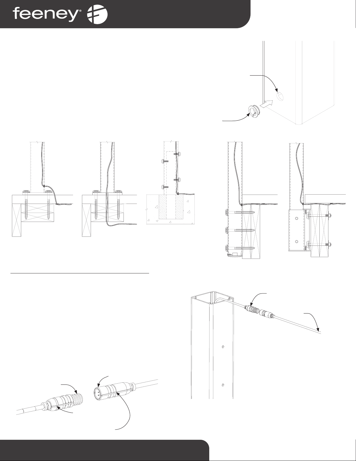
Step 1B - Drill Posts and Route Starter Cable
Determine the post that will act as the starng post, this will likely
be designated on the lighng layout schemac received with the
order. Installing the starter cable through the post is easiest when
done prior to mounng the post.
Determine the locaon that the starter cable will enter the starng
post.
Note: Depending on the post mounࢼng method, and driver locaࢼon
relaࢼve to the post, the starter cable entrance point may vary. (See
Figure 1.2 for typical recommendaࢼons) Figure 1.1
1/2" DIA.
HOLE
GROMMET
PART #1114
WIRE COMES
UP THROUGH
DECKING AND
INTO POST.
WIRE CAN BE RUN
IN CONDUIT BURIED
IN CONCRETE, OR
RUN DIRECTLY
FROM ENCLOSURE
TO POST. WIRE
INSIDE POST RUNS
BETWEEN INSIDE
POST WALL AND
STANCHION.
WIRE RUNS UNDER
DECK THROUGH
FASCIA BOARDS
AND ENTERS POST
BELOW DECKING
SURFACE BETWEEN
FACSIA AND POST
FACE.
WIRE RUNS
UNDER DECK AND
ENTERS POST
ABOVE FASICA
BRACKET BELOW
DECKING.
WIRE RUNS UNDER
DECK THROUGH 3/4"
HOLE IN BASEPLATE
AND BLOCKING.
(3/4" HOLE DRILLED BY
CUSTOMER)
Figure 1.2
For systems with Series 200, 300, 350, or 450 top rail:
Fish the connector for the starter cable through the post and out
of the top, and aach LED 2-Way Splier to Starter Cable (See
Figure 1.3).
IMPORTANT NOTE: Maintaining the polarity at all connec-
on points is crical. Constant alignment verificaon
of the of the posive and negave signs will guarantee
less problems and rework.
Use masking tape to temporarily secure starter cable to outside
of post to prevent retracng back into post.
2-WAY
SPLITTER
STARTER CABLE
Figure 1.3
MALE CONNECTOR
FEMALE CONNECTOR
Keep the straight line
on the outside maࢼng
connecࢼon aligned
1-800-888-2418 | www.feeneyinc.com 5
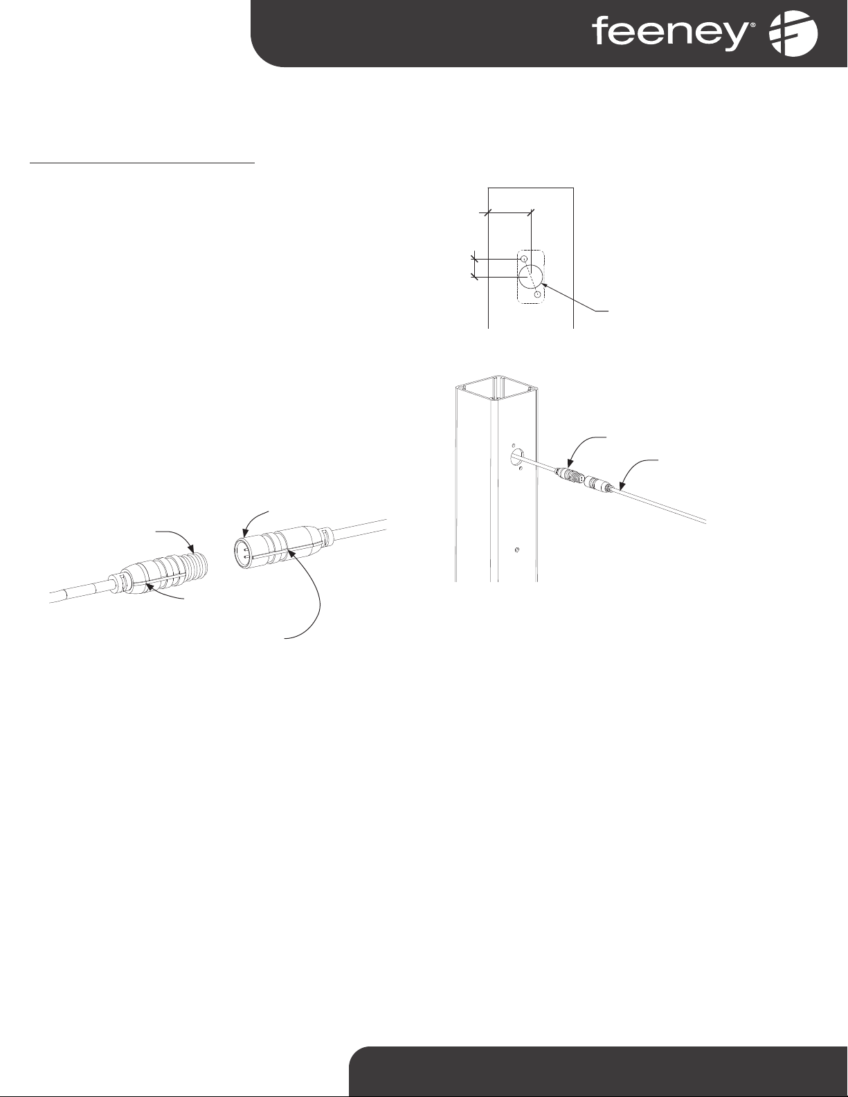
Step 1B – Conঞnued
For systems with Series 150 top rail:
Drill a 1/2” diameter hole vercally centered between the
factory pre-drilled top rail RCB holes. This will allow the LED
2-way splier and LED extension cable to pass through the RCB
hollow (See Figure 1.4). Repeat this step for each post which will
have post accent lights installed. For stair posts, pre-drill top rail
RCB holes as needed, and then pre-drill 1/2" diameter hole.
Pull one branch of the LED 2-way splier out through drilled
hole between RCB holes, and aach LED Extension Cable to the
other branch (See Figure 1.5).
IMPORTANT NOTE: Maintaining the polarity at all con-
necon points is crical. Constant alignment verifi-
caon of the of the posive and negave signs will
guarantee less problems and rework.
Use masking tape to temporarily secure starter cable to outside
of post to prevent retracng back into post.
1/2" HOLE
1-3/16"
1/2"
TOP OF POST
Figure 1.4
Figure 1.5
2-WAY SPLITTER
STARTER CABLE
MALE CONNECTOR
FEMALE CONNECTOR
Keep the straight line
on the outside maࢼng
connecࢼon aligned

1-800-888-2418 | www.feeneyinc.com6
Step 2 - Prepare Posts and Run Wiring
Step 2A – Prepare Post for Mounঞng Plate
Locate the mounng plate in the desired locaon on the post.
Place the top of the plate at least 4-1/2” down from the top of
the post. Using the mounng plate as a guide, mark the locaons
of the four mounng holes, and the lead wire hole (See Figure 2.1).
Set the mounng plate aside. Pre-drill the four mounng pilot
holes using a 1/8” diameter drill bit. Pre-drill the lead wire pilot
hole using a 1/2” diameter drill bit (See Figure 2.2).
Step 2B – Run Wiring
For systems with Series 200, 300, 350, or 450 top rail:
String an extension cable between each post, and connect
a 2-way splier. Feed one branch of the splier out through
the 1/2" lead wire pilot hole drilled in the previous step, this
becomes the lead wire for the light at this post. Feed the other
branch of the 2-way splier over the top of the post and connect
an extension cable (See Figure 2.3).
Note: A 2-way splier does not need to be used at the final post, as the
extension cable will connect to the final light to complete the circuit.
Use masking tape to temporarily secure lead wire to outside of
post to prevent retracng back into post.
MOUNTING
PLATE
4-1/2" MIN
Figure 2.1
(4x) 1/8"
MOUNTING
PILOT HOLES
1/2" LEAD WIRE
PILOT HOLE
Figure 2.2
Figure 2.3
EXTENSION
CABLE
LEAD WIRE
2-WAY
SPLITTER

1-800-888-2418 | www.feeneyinc.com 7
Step 3A – Aach Mounঞng Plate
Aach the mounng plate to the post using two of the provided
#8 x 3/4” self-tapping screws (See Figure 3.1).
Important: Use only the top two mounࢼng holes at this ࢼme.
Step 2B – Conঞnued
For systems with Series 150 top rail:
String an extension cable between each post, feeding it through
the RCB and 1/2" hole, then connect a 2-way splier. Feed one
branch of the splier out through the 1/2" lead wire pilot hole
drilled in the previous step, this becomes the lead wire for the
light at this post. Feed the other branch of the 2-way splier
through the 1/2" hole and the hollow of the RCB and connect
an extension cable (See Figure 2.4).
Note: A 2-way splier does not need to be used at the final post, as the
extension cable will connect to the final light to complete the circuit.
Use masking tape to temporarily secure lead wire to outside of
post to prevent retracng back into post.
Step 3 - Install Post Accent Lights
Figure 2.4
Figure 3.1
EXTENSION
CABLE
LEAD WIRE
2-WAY
SPLITTER
1-800-888-2418 | www.feeneyinc.com8
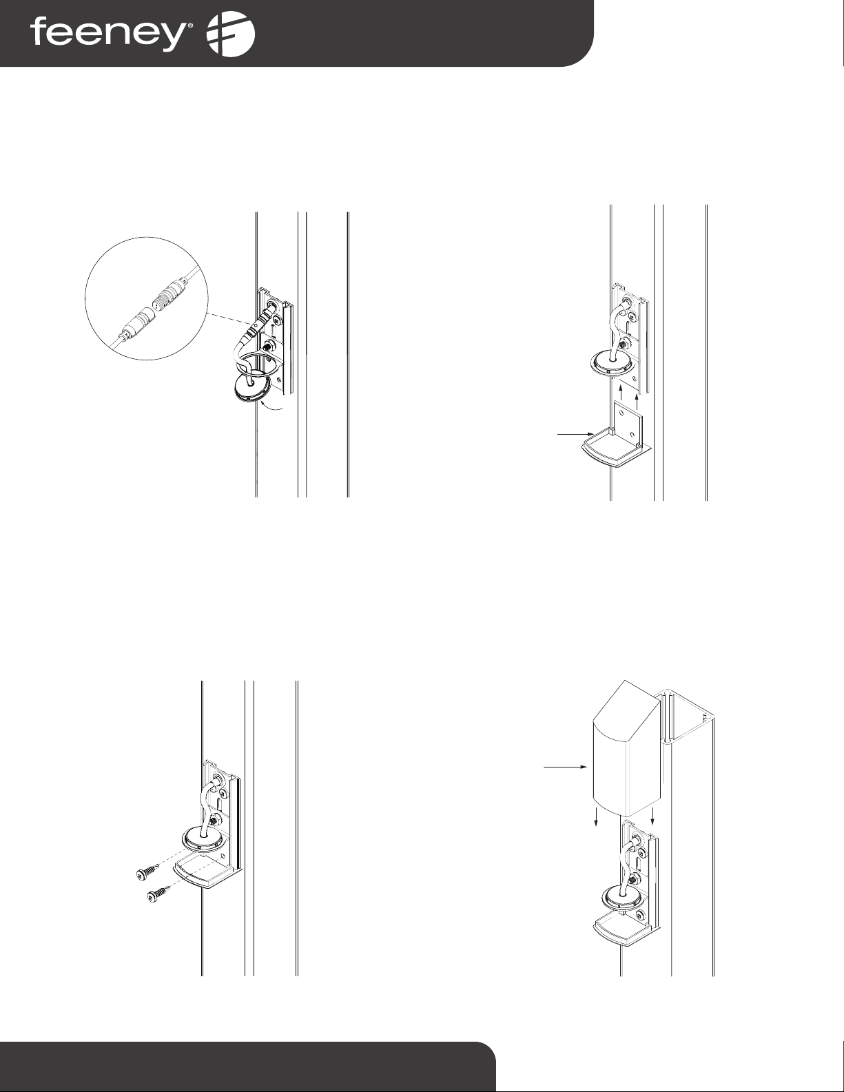
Step 3B – Aach LED Array
Feed LED array lead wire through array bracket and aach to
splier branch or . Push excess wiring and connectors back into
post through the power source lead wire hole. Insert LED array
into bracket and snap into place to secure (See Figure 3.2).
Step 3C – Insert Lens
Slide the lens onto the mounng plate, by inserng back plate
into angled receiver flanges on mounng plate (See Figure 3.4).
Step 3D – Secure Lens
Secure the lens and the mounng plate to the post using two of
the provided #8 x 3/4” self-tapping screws (See Figure 3.5).
Step 3E – Aach Cover
Aach the cover onto the mounng plate by aligning the tabs on
the cover with the slot on the sides of the mounng plate and
sliding the cover down unl it comes into contact with the lens
(See Figure 3.6).
POWER
SOURCE
LEAD WIRE
LENS
COVER
Figure 3.2 Figure 3.4
Figure 3.5 Figure 3.6

1-800-888-2418 | www.feeneyinc.com 9
Step 4 - Aperature Adjustments (opঞonal)
Step 4A – Loosen LED Array Bracket
Slide the cover upwards on mounng plate, enough to expose
the nut on the LED array bracket. Loosen the nut (See Figure 4.1).
Step 4B – Adjust LED Array Bracket
Slide the LED array bracket up or down to acheive desired light
aperture (See Figure 4.2).
Step 4C– Tighten LED Array Bracket
Once the LED array bracket is in the desired locaon, ghten the
nut on the LED array bracket (See Figure 4.3).
Step 4D – Re-aach Cover
Slide the cover down unl it comes in contact with the lens (See
Figure 4.4).
Figure 4.1 Figure 4.2
Figure 4.3 Figure 4.4

1-800-888-2418 | www.feeneyinc.com10
LED Post Accent Light - Troubleshooঞng
Scenario #1 - If all locaঞons do not illuminate, there could be a polarity issue
1. Turn offAC circuit breaker prior to connuing the next procedure.
2. Swap the wires at the driver terminals
3. Replace cover on driver unit
4. Turn on AC circuit breaker
5. Power up the driver and check all LED locaons for illuminaon
Scenario #2 - Some LED locaঞons are illuminated but others are not
1. Note which locaons are not illuminang
2. Turn offAC circuit breaker prior to connuing to next procedure
3. Rotate the connector 180 degrees at each noted locaon where the array is not illuminang
4. Repeat at all noted locaons that did not illuminate
5. Turn on AC circuit breaker
6. Power up the driver and check all locaons for illuminaon

www.feeneyinc.com
1-800-888-2418
©2021 Feeney, Inc. (10/21)
This manual suits for next models
2
Table of contents
Popular Outdoor Light manuals by other brands

EE Systems Group
EE Systems Group eLEDing EE801WLW Setup Instruction

HEPER
HEPER LIA Installation & maintenance instructions

Home Decorators Collection
Home Decorators Collection CAMBRIDGE GEM1801A Use and care guide

KMART
KMART Marmo SLR-15024 quick start guide

Yeelight
Yeelight Staria Bedside Lamp Pro user manual

Enlite
Enlite EN-WU021 manual


