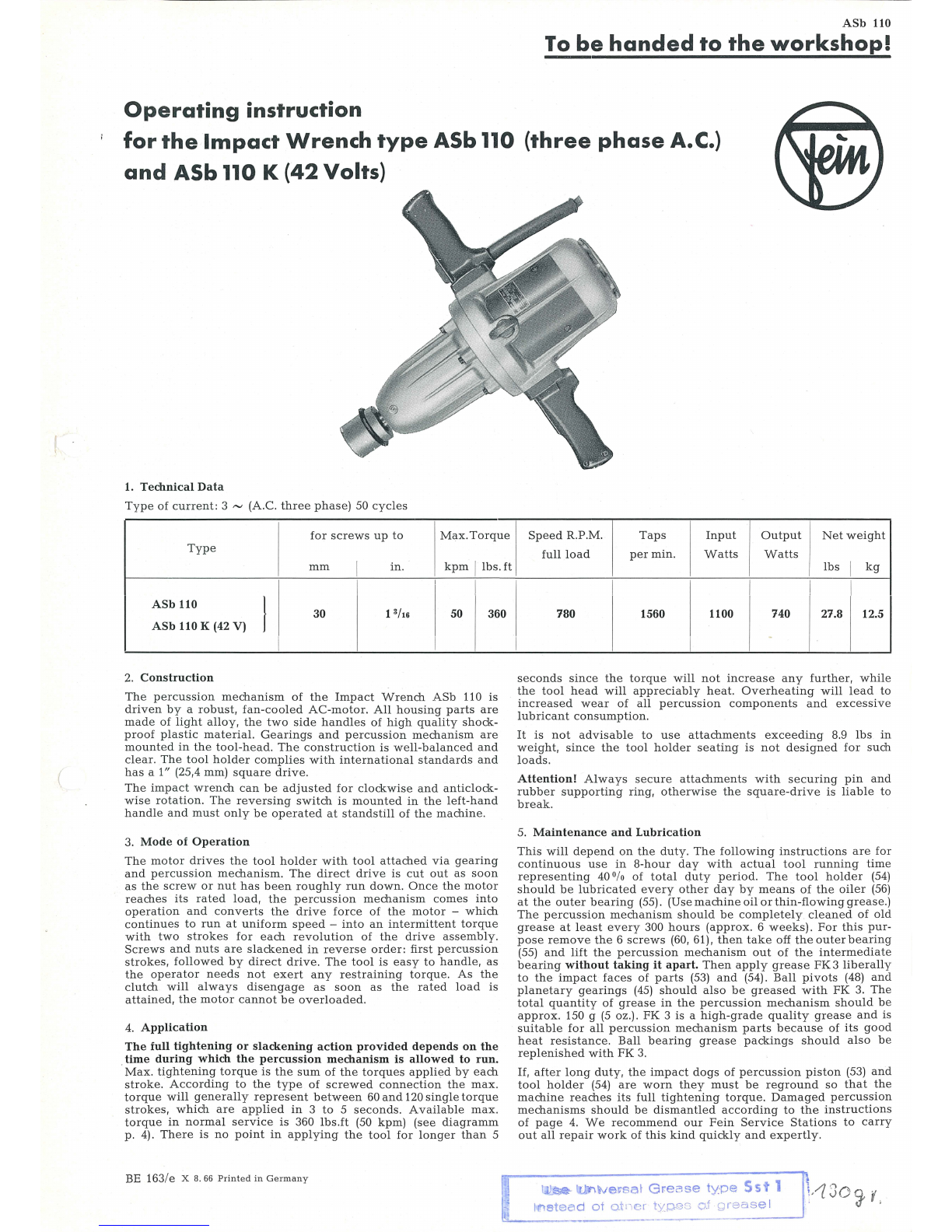
Fein ASb 110 User manual

ASb
110
To
be
handed
to
the
workshop!
Operating
instruction
for
the
Impact
Wrench
type
ASb 110
(three
phase
A.
C.)
and
ASb110 K
(42
Volts)
1.
Technical
Data
Type
of
current:
3
~
(A.C.
three
phase)
50
cycles
for
screws
up
to
Max.
Torque
I
Type
mm
I
in
.
kpm
llbs.
ft
I
ASb
110 } 13
/t6
30
50 360
ASb
110 K (42 V)
2.
Construction
The
percussion
mechanism
of
the
Impact
Wrench
A
Sb
110
is
driven
by
a
robust,
fan-cooled
AC-motor.
All
housing
parts
are
made
of
light
alloy,
the
two
side
handles
of
high
qualit
y
shock-
proof
plastic
material.
Gearings
and
percussion
mechanism
are
mounted
in
the
tool-head.
The
construction
is
well-balanced
and
clear.
The
tool
holder
complies
with
intern
at
ional
standards
and
has
a 1" (25,4 mm)
square
drive.
The
impact
wrench
can
be
adjusted
f
or
clockwise
and
anticlock-
wise
rotation.
The
reversing
switch
is
mounted
in
the
left-hand
handle
and
must
only
be
operated
at
standstill
of
the
machine
.
3.
Mode
of
Operation
The
motor
drives
the
tool
holder
with
tool
attached
via
gearing
and
percussion
mechanism.
The
direct
drive
is
cut
out
as
soon
as
the
screw
or
nut
has
been
roughly
run
down.
Once
the
motor
reaches
its
rated
load,
the
percussion
mechanism
comes
into
operation
and
converts
the
drive
force
of
the
motor
-
which
continues
to
run
at
uniform
speed
-
into
an
intermittent
torque
with
two
strokes
for
each
revolut
ion
of
the
dri
ve
assembly.
Screws
and
nut
s
are
slackened
in
reverse
order:
first
percussion
strokes,
followed
by
direct
drive.
The
tool
is
easy
to
h
an
dle,
as
the
operator
needs
not
exert
any
restraining
torqu
e.
As
th
e
clutch
w
ill
a
lways
disengage
as
soon
as
th
e
rat
ed l
oad
is
attain
ed,
the
motor
cannot
be
overloaded.
4.
Application
The
full
tightening
or
slackening
action
provided
depends
on
the
time
during
which
the
percussion
mechanism
is
allowed
to
run.
Max.
tightening
torque
is
the
sum
of
the
torques
applied
by
each
stroke.
According
to
the
typ
e
of
screwed
connection
th
e
max
.
torq
ue
will
generally
re
present
between
60
and
120s
in
gle
torqu
e
strokes,
which
are
appli
ed
in
3
to
5
seconds.
Ava
ilabl
e
max.
torque
in
normal
servic
e
is
36
0
lbs.ft
(50
kpm
)
(see
diagramm
p.
4).
There
is
no
point
in
app
ly
ing
the
tool
for
long
er
than
5
BE 163
/e
X 8.
66
Printed
in
Germany
I
Speed
R.P.M.
Taps
Input
Output
Net
weight
full
load
per
min.
Watts
Watts
lbs
I
kg
I ! I
780 1560 1100 740 27.8 12.5
seconds
since
the
torque
w
ill
not
increase
any
further,
while
the
tool
head
will
appreciabl
y
heat
.
Overheating
will
lead
to
incr
eased
wear
of
all
percussion
componen
ts
and
excessive
lubricant
consumption
.
It
is
not
advisable
to
us
e
attachments
exceed
i
ng
8.9
lbs
in
weight,
since
the
tool
hold
er
seating
is
not
de
signed
for
such
loads.
Attention!
Alwa
ys
secure
attachments
with
securing
pin
and
rubber
supporting
ring
,
otherwise
the
square-dri
ve
is
liable
to
break
.
5.
Maintenance
and
Lubrication
This
w
ill
depend
on
the
dut
y.
Th
e
following
instructions
are
for
continuous
us
e
in
8-hou
r
day
with
actual
tool
running
time
representing
40
Ofo
of
total
c!.uty
period.
The
tool
holder
(5
4)
should
be
lubricat
ed
every
o
the
r
day
by
means
of
t
he
oiler
(56)
at
the
outer
bearing
(55). (Use
machine
oil
or
thin-flowing
grease
.)
The
percussion
mechanism
should
be
completely
cleaned
of
old
grease
at
least
every
300
hours
(approx.
6
weeks).
For
this
pur-
pose
remove
the
6
screws
(60, 61).
then
take
off
theouterbearing
(55)
and
lift
the
percussion
mechanism
out
of the
intermediate
bearing
without
taking
it
apart.
Then
apply
grease
FK
3
liberall
y
to
the
impact
fac
es
of
par
ts
(53)
and
(54).
Ball
pivots
(48) and
planetary
gearings
(45)
should
also
be
greased
w ith
FK
3.
Th
e
total
quantity
of
grease
in
t
he
percu
ssion
mechanism
should
be
ap
prox.
150 g (5 oz.).
FK
3
is
a
high
-
grade
quali
ty
grease
and
is
suitable
for
all
percussion
mechanism
parts
because
of
its
good
heat
resistance.
Ball
bearing
grease
packing
s
should
also
be
replenish
ed
with
FK
3.
If,
after
long
duty,
the
impact
dogs
of
percussion
piston
(53)
and
tool
holder
(54)
are
worn
they
must
be
reground
so
that
the
machine
reaches
its
full
tightening
torque.
Damaged
percussion
me
chanisms
should
be
dismantled
according
to
the
instru
ctions
of
page
4.
We
r
ec
ommend
our
Fein
Servic
e
Stations
to
carr
y
out
a
ll
repair
work
of
this
kind
quickly
and
expe
rtly
.
lJJ~
ll);Niversat
Grease
type
Sst
1
llhetead
ot
oto-,er
types
o.t
grease
I

r-
,
I
I
I
I
55
56
he
ad
offset
through
90°
40_7
___
_
32
---
-
(>
r'(?
I I ! : I
28 1 'i
2s
1
.
26
2
~
24
\ I
59
61
62
58
--
38- -
·.
Impact Wrench
ASb
110 37-
--
--
--jj.lr=flr
34
33
35
36
I I I
I
3
-
~
I
I
22
21
20
19
23
39
\19
7:
S
ect
ion A-B
11
-·-
/ -
14
/ ·
15
<:::>
"'
'-7-
~
18
I
1
31
t:=
30
-
12
1J,
offset
through
90 °
··
---
40
=t:.=-~
~
--
--
41

Component Parts
0
z
Order
....,
Description
....
Reference
;:.,
"'
....,
p.. 0
0
z
Order
....,
Description
....
Reference
;:.,
"'
a
p..
1-18
MK
3-88-1 1
motor
housing,
assembled
40
GH
4-65 1 u
pper
handle
part
1
MK3-88
1
motor
housing
41
SR 3-M4x25 2 fillister
screw
3
state
t
ype
1
stator
assembled
with
winding
and
voltage
4
SR
12-40 2
hexagon
screw
42-44 EZ 1-55-1 1
re
versi
ng
switch,
assembled
42 EZ 1-55 1
reversing
switch
5
PT
37-11 2
securing
plate
43 EZ 19-41 1
connecting
cable
6 BF 20-24 2
pressure
piece
44 EZ 19-42 1
con
n
ecting
cable
7
SR
14-31 4
fillister
screw
8
PT
5-M6
4 el
astic
lock
washer
9
JS
19-12 2
cable
sleeve
10
SR
3-M4x8
1
fillister
screw
for
earthing
11
MZ
37-29 1
earth
screw
12
BU 10-30 1
threaded
sleeve
13
SR
27-7 1
ring
screw
14
PT
11-33 1
cover
plate
15
RJ
24-8
washers
as
required
16
RJ
30i-
30x
1,2 1
circlip
Seeger
17
PT
35-38 4
protecting
cover
18
SR6k-M5x12
1
fillister
countersunk
screw
19-21
WL
1-50-2 1
rotor
with
fan
45-53 A 10-7-1 1 drive
assembly
45 A 10-7 1
dr
ive
assembl
y
46 LK 1-50 1
groove
ball
bearing
47 WB 6-74 1
intermediate
s
haft
48 A 11-4 2
ball
pivot
49 A 11-5 4
suppo
rting
bolt
50 LK 15-2 1
ball
cage
51
LK 10-18 1
pressure
bearing
ring
52
FDl-174
1
pressure
spring
53 A 12-9 1
percussion
piston
54
A4-34
1
too
l
holder
55, 56 LA 9-52-1 ! 1 outer
bearing,
assembled
22 FL 1-110 1
fan
wheel
56
MZ3
1-1
1
oiler
23 LK 16-1 1
groove
ball
bearing
57
SR33
-M5
x25
8
hexagon
socket
scre
w
24-28
LA
6-138-1 1
intermedia
te
bearing,
assemb
l
ed
58
SR33-M6x25
3
hexagon
socket
screw
24
LA
6-138 1
intermediate
bearing
59
PT
6a-6 9 lock
was
h
er
25 LK 1-36 1
groove
ball
bearing
26
RJ
27a-35x19,5 2
Nilos
ring
27
PT
16-53 1
bearing
plate
28
SR2-M4x18
3
cylindrical
screw
60
SR33-M6x55
3
hexagon
socket
sc
re
w
61
SR33-M6x35 I 3
hexagon
socket
scre
w
62
RJ
24-50 i
wa
sher
I
29-36
GH
4-64-3 1
handle,
assembled
with
switch
Accessories
and
cable
z85 f-27 1
hexago
n
socket
to
ol
29-35
GH
4-64-2 1
handle,
assembled
with
switch
BF 35-9 1
securing
pin
29-31
GH
4-64-1 1
handle,
assembled
29
GH
4-64 1
lower
handle
part
30
GH
4-65 1
upper
handle
part
31
SR3-M4x25
2
fillister
screw
JS
19-5 1
rubber
ring
MZ60
-3/
FG4
1
tube
of
grease
z10
-7
1
socke
t
spanner
z10-8 1
socke
t
spanner
32 EZ 1-48 1
switch,
3
po
l
es
I
33
PT
31-21 1
cab
le
clamping
bridge
34 SR3-M3,5x15 2
fillister
countersunk
screw
Accessories
on
demand
35
JS
13-52 1
cable
protecting
sleeve
36 EZ 6-99 1
cable
without
plug,
16ft
I
MZ
26-14-2
1
1 I
vertical
suspension
de
vice
37-44
GH
4-66-2 1
handle,
assembled
with
reversing
switch
37
-41
GH
4-66-1 1
handle,
assemb
l
ed
37
GH4-66
1
lower
handle
part
38
JS
28
-2 1
ins
ert
39
JS
16-39 1
plug
Connecting
plan
of
the
machine

6.
Dismantling
of
the
machine
a)
Uns
c
re
w
six
screws
(60)
and
(61).
then
t
ake
off
outer
bearing
(55).
b)
Dra
~
out
pe
rcu
ss
ion
m
ec
hanism
to
the
fr
ont.
c)
Unscrew
thre
e
screws
(58)
and
remove
in
t
er
m
ed
iat
e
bearing
(24)
with
rot
or
(1
9-23).
d)
Open
handle
and
clamp
off
connecting
cables
of
the
sw
itche
s.
Distribution
of
connections
see
connecting
plan
page
3.
e)
Unscrew
axial
fixing
screws
(4)
and
radi
al
screws
(7).
Pu
sh
stator
(3)
out
of
motor
housing.
\
Fig.
1
7.
Dismantling
of
the
percussion
me
c
hanism
a)
Turn
percuss
ion
p
iston
(53)
un
til
ball
pi
v
ot
(4
8)
is
paralle
l
to
axis.
b)
Fix
percussion
mec
hanism
in
the
vic
e
and
pre
ss
spring
(5
2)
until
it
stops
. The
upper
ball
pivo
t
slides
in
the
percussion
m
ec
hanism
ou
t
of
its
sea
ting
into
the
bo
re
Cb
24
. (See fig. 1).
Her
eby
th
e
transve
r
se
s
up
por
ting
bolt
(49)
in
the
percussion
pist
on
is
mad
e
access
ibl
e
and
ma
y
be
pus
hed
o
ut
.
Remov
e s
econd
su
ppo
r
ting
bo
lt
in
perc
ussion
pi
sto
n
in
the
same
mann
er.
c)
Release
per
cussion
mechanism
.
Remov
e
percu
ssion
pis
t
on
(53).
pres
s
ur
e
spr
ing
(52).
ring
(5
1),
needle
cage
(50)
a
nd
intermediate
sh
aft
(47).
d)
Put
dri
ve
assemb
ly
(4
5)
w
ith
ball
pi
vo
ts
(48)
in
a
ve
r
tica
l
position.
Incline
ba
ll
pivots
to
cen
t
er
ax
is.
Push
suppor
ti
ng
bolts
(4
9)
ou
t
of
dr
i
ve
asse
mbl
y.
See
fig. 2.
Fig. 2
Re-assemble
in
re
v
erse
sequence
.
Make
sure
that
su
pporting
bolts
fit
co
rrectl
y
in
t
heir
original
posi
t
ion.
The
ball
cage
serves
as
counterbearing
of
the
ba
ll
pivo
t.
The
cylindrical
recess
is
required
for
fre
e
move
me
nt
of
th
e
ball
pivot
shank
.
The
ball
pivots
are
correctl
y
fitted
when
the
r
ecess
at
the
fr
ont
part
is
para
ll
el
to
th
e m
ac
hin
e
ax
is.
Diagram
for
the
destination
of
favorable
time
of
tightening
action
Standard
~
~
Screws
50
_,.,.
"""""""
~~
~
Example
E
n..
"""
~
-- '
l-
--
f--
--
,
c 40
C1)
::>
J
I -
....
·-
-
E"
.2
I 1.,--""'
II v
Ol
c I
~
c 30
2
_c:
Ol
f.=
v
I
I
II
'-
·-
~.-~oo··
20
'i
l'
/
I 1/
I
10
I
~
0 1 2 3 4 5 6 7 8 9 w
Hard
ba
s
e:
El
as
tic
base:
Soft
base:
e. g. screws
and
nuts with
was
he
rs
DIN 125
e.
g.
lock
was
her
s,
stay
bolts,
extensions
e. g.
wood
,
lead
or
fiber
washers,
packings
High-tensile screws
Striking
ti
me
in
seconds
(
This manual suits for next models
1
Other Fein Impact Driver manuals
Popular Impact Driver manuals by other brands

Sealey
Sealey GSA6006 instructions

Paoli Avvitatori
Paoli Avvitatori RED DEVIL 2.0 street legal Operating and maintenance manual

Matco Tools
Matco Tools MCL2012BIW operating instructions

Sunex Tools
Sunex Tools SX4360-6 operating instructions

Parkside
Parkside PDSSE 550 A1 Translation of the original instructions

ACDelco
ACDelco ARI1278-3 Product information manual