Fence Mower FM30 Installation instructions

OPERATOR’S AND MAINTENANCE MANUAL
FM30-FM60
For support and contact information
Visit: www.fencemower.com Phone: 713-501-5356
DANGER
Read this manual and the
manual for your tractor
carefully to acquaint yourself
with both machines before
operating!
FOR SERIAL #s STARTING
WITH 1057
RELEASED 11/3/17

MODEL NUMBER
SERIAL NUMBER
DATE OF PURCHASE
Customer Pre-Operation Check List Reference
Read, understand and follow the general safety rules listed in
this manual. Page 2
Check decals for position and legibility Page 3
Check all blades for sharpness and condition. Page 7
Check gearbox lube level. Page 8

Table of Contents
© Copyright 2016 All Rights Reserved
Wright Fence Mower, LLC provides this publication “as is” without warranty of any kind, either expressed or implied. Every precaution has been taken in the design of this manual;
however Wright Fence Mower, LLC assumes no responsibility for errors or omissions. Neither is any liability assumed for damages resulting from the use of the information contained
herein. Wright Fence Mower, LLC reserves the right to revise and improve this product at any time. The illustrations in this manual are not intended for the safe and proper assembly or
disassembly of this product, but for parts ordering reference only.
REVISED 11/3/2017
Section 1 INTRODUCTION
1
Owner’s Responsibility
1
Purpose of this Manual
1
Safety-Alert Symbol
1
Signal Words
1
Customer Assistance
1
Section 2 SAFETY INFORMATION
2
General Safety Rules
2
General Safety Rules Continued
3
Safety Decals
3
Section 3 ASSEMBLY INSTRUCTIONS
4
Assembly
4
Diagram/Photo
4A
Section 4 OPERATING INSTRUCTIONS
5
Operation
5
Lights, SMV Emblems
5
Low Speed
5
Normal Procedures
5
Traveling
5
Mowing
5
Reverse Operation
5
Obstacles
5
Positioning
5
Height Adjustment
5
Section 5 LUBRICATION
6
Spindle
6
Driveshaft
6
Tail Wheel
6
Section 6 MAINTENANCE
7
Blades
7
Check Blade Condition
7
Remove Blades
7
Replace Blades
7
Gearbox
8
Gearbox Lube Level
8
Gearbox Seals and Gasket
8
Input Shaft Seal and Cover Gasket
8
Output Shaft Seal
8
Gearbox Mounting Hardware
8
Tail Wheel
8
Replace Wheel
8
Replace Pivot
8
Reference – Parts Lists
9-14
Torque Specifications Coarse Thread
15
Torque Specifications Fine Thread & Head Markings
16
Warranty
17

Section 1
Wright Fence Mower, LLC
INTRODUCTION
FM30-FM60 1
Owner’s Responsibility
The manufacturer has no control over the ultimate use
of the mower and therefore assumes no responsibility
or liability for damage or injury resulting from the use
of this machine.
The upkeep of the fence mower is the responsibility of
the user. This upkeep includes all shielding, guards,
and safety decals (OSHA Regulation 1928.57). You
can obtain replacement parts from Wright Fence
Mower, LLC.
Read this Operator's Manual before operating the
mower. Failure to do so could result in serious injury
or death to the operator or to others. Remember that
most accidents occur due to neglect or carelessness.
The operator is responsible for inspecting and making
repairs as may be necessary. Cleaning after each use
and storage under a shelter will extend the life of the
mower.
Purpose of This Manual
This manual provides information on safety, operation,
adjustments, troubleshooting and maintenance of your
new mower. Please read and follow all the
recommendations to help ensure that you get many
years of service from your new Wright mower.
If you need additional copies of this manual please
contact Wright Fence Mower, LLC. and request part
number 24551.
Safety-Alert Symbol
This symbol is the safety alert symbol. It
appears throughout this manual to call your
attention to instructions involving your personal
safety and the safety of others. Failure to follow
these instructions can result in injury or death.
Signal Words
Safety signal words are words that call attention to the
safety sign and designate a degree or level of hazard
seriousness. The signal words used throughout this
manual are DANGER, WARNING and CAUTION.
Please read and follow all safety messages that have
these signal words shown for your protection.
DANGER
Indicates an imminently hazardous situation which, if
not avoided, will result in death or serious injury.
WARNING
Indicates a potentially hazardous situation which, if not
avoided, could result in death or serious injury.
CAUTION
Indicates a potentially hazardous situation which, if not
avoided, may result in minor or moderate injury.
Customer Assistance
The Wright Fence Mower, LLC sales team would like
you to be satisfied with your new FENCE MOWER. If
for some reason you have any questions about the
information in this manual or have a problem with your
mower and need further assistance, please contact:
WRIGHT FENCE MOWER, LLC
For support and contact information
Visit: www.fencemower.com or call: 713-501-5356
Section 2
Wright Fence Mower, LLC
SAFETY INFORMATION
FM30-FM60 2
General Safety Rules
READ AND FOLLOW THE INSTRUCTIONS IN THIS
OPERATING MANUAL AND ESPECIALLY IN THIS
SAFETY SECTION. FAILURE TO DO SO CAN
RESULT IN SERIOUS INJURY OR DEATH.
WARNING
SAFETY of the operator is one of the main concerns in
designing and developing the fence mower. However,
every year accidents occur which could have been
avoided by a few seconds of thought and a more
careful approach to handling equipment. You, the
operator, can avoid many accidents by observing the
following instructions in this manual and insist those
working with you, or for you, to follow them.
DANGER
NEVER allow an UNQUALIFIED OR UNDERAGE
person to operate the mower.
NEVER use alcoholic beverages or drugs that can
hinder alertness or coordination while operating this
equipment. Consult your doctor about operating this
machine while taking prescription medications.
WARNING
MANY varied objects, such as fence wire, can become
entangled in the operating parts of the mowing and dirt
removal blade. These items MUST BE AVOIDED.
Inspect the fence lines for loose wires, and wires that
may be buried. DO NOT ATTEMPT TO OPERATE
THE EQUIPMENT WHERE LOOSE WIRES, OR
WIRES THAT ARE NOT SECURED BY THE FENCE
POST. Repair the fence before attempting to mow
underneath.
WARNING
ALWAYS stop the tractor, disengage the PTO, set
parking brake, turn off the tractor engine, remove key
and wait for all rotary motion to stop BEFORE
dismounting the tractor.
NEVER leave the equipment unattended with the
tractor running.
DANGER
NEVER place hands or feet under the mower with
the tractor engine running or before you are sure all
motion is stopped. Stay clear of all moving parts.
DO NOT reach or place any part of your body under
equipment until it is blocked securely.
DANGER
THE rotating parts of this machine have been designed
and tested for rugged use. However, they could fail
upon impact with heavy, solid objects such as steel
guardrails, and concrete abutment. Such impact could
cause the broken objects to be thrown outward. To
reduce the possibility of damage to the equipment,
serious injury, or even death, never let the mowing and
dirt removal blade come into contact with such
obstacles.
WARNING
STAY alert for uneven terrain, loose fence wire and
hidden hazards. Keep away from drop-offs and
hazards that could cause roll over. Use extreme care
and maintain minimum ground speed when operating.
Avoid operating on steep slopes.
WARNING
ALWAYS transport the fence mower in a lifted (up)
position behind the tractor when moving from one
location to another.
DANGER
UNDER no circumstances should children under the
age of 18 be allowed to work with this equipment. Do
not allow persons to operate or assemble this unit until
they have read this operating manual and have
developed a thorough understanding of the safety
requirements.
DANGER
THIS equipment is dangerous to children and persons
unfamiliar with farm machinery.
WARNING
THE Fence Mower is designed for use only on tractors
with 540-RPM power takeoff. Disengage the power
takeoff (PTO) and place the transmission in neutral
before attempting to start the engine.
WARNING
NEVER exceed the limits of a piece of equipment. If it’s
ability to do a job, or to do so safely, is in question -
DON'T TRY IT.

Wright Fence Mower, LLC
SAFETY INFORMATION
FM30-FM60 3
General Safety Rules Continued
DANGER
DO NOT modify this equipment in any way.
Unauthorized modification could result in serious
injury or death and may impair the function and life of
the machine.
WARNING
IN addition to the design and the confirmation of this
equipment, including safety signs and safety
equipment, accident prevention is dependent upon the
awareness, concern, prudence, and proper training of
personnel involved in the operation, transport,
maintenance and storage of the machine.
WARNING
THE use of this equipment is subject to certain
hazards that cannot be protected against by the
mechanical means or product design. Most accidents
occur because of neglect or carelessness. Keep all
helpers and bystanders at least several hundred feet
from operating the Fence Mower. Only properly
trained people should operate this machine.
Safety Decals
Your Wright Fence Mower ships with all safety decals
in place. They are located in areas on the mower that
are potentially hazardous. Please locate, read and
follow the information you find on these decals.
By law, you must replace any safety decals that are
damaged or missing. You can order a replacement
decal kit from Wright Fence Mower, LLC. Ask for part
number 16808 when ordering.
To apply the replacement decals:
Clean the surface to place the new decal.
Peel the decal away from the paper backing.
Press firmly onto the clean surface.
Squeeze out any air pockets using a straight
edge.

SECTION 3
Wright Fence Mower, LLC
ASSEMBLY INSTRUCTIONS
FM30-FM60 4
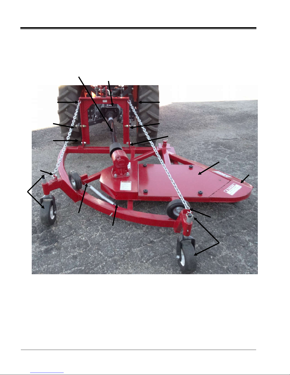
ASSEMBLY
Before beginning the assembly of your Wright
Fence Mower, read 1) the entire Operating
Manual, 2) the warning decals and 3) the PTO
manual provided. Once this is done, read
and follow the below instructions.
PLEASE REFER TO THE DIAGRAM/PHOTO
ON THE NEXT PAGE (_)
DENOTES A REFERENCE
Step 1. Remove and discard the straps holding
the mower to the pallet. (Use proper eye
protection)
Step 2. Remove the cardboard box containing the
trailing wheels.
Step 3. Remove the swing arm cover (A)
and take out the parts packages. The parts
packages will contain the following:
• (2) ¾” bolts, washers, and nuts
• (2) Category 1 lifting arm pins
• (2) Chain with chain links attached
• (1) PTO 1/2” bolt and nut (shear pin)
• (1) Spring
Step 4. Lift-up on the swing arm (B) and
pull it outward. Remove the A-frame (C) and
then return the swing arm to its original position.
Step 5. Attach the A-frame to the base frame
using the two ¾” bolts, washers, and nuts. (D)
Tighten, but allow for some movement of the
A- frame.
Step 6. Attach the category 1 lifting arm pins to
the A-frame and tighten. (E)
Step 7. Extend the swing arm (B) out to the
mowing position.
Step 8. Attach the longer eyebolt to the swing
arm. (F)
Step 9. Attach the shorter eyebolt to the base
frame. (G)
Step 10. Attach the spring to the two eyebolts.
Adjust to permit some slack (one inch) in the
swing arm.
Step 11. Attach the chains from the tail wheels
to the A-frame, as shown. (H)
Step 12. Attach the fence mower to your tractor
using the 3-point hitch. Once attached to your
tractor, start the tractor and lift the fence mower
off the ground high enough to remove the pallet.
Step 13. Remove the trailing wheels from the
cardboard box. Insert the wheels so they are below
the frame. (I) (Spacers are provided to adjust the
desired wheel height.) Insert the locking pins after
adjusting. (I)
Step 14. Install the PTO driveline. (J)
Step 15. Lift-up the fence mower using the lifting
arms of the tractor. Check to make sure there is
clearance between the mower and the rear
tractor wheels. Check to see how close you will
need to be to the fence line when cutting.
Step 16. Lower the mower, clear everyone away,
and engage the PTO to check blade rotation.
Step 17. Lower the fence mower to where the tail
wheels touch the ground. You should have a little
slack in the chain.
Step 18. Before mowing under your fence line,
operate the mower away from the fence.
Make sure the front and back of the mower are
even. Do not operate with the front of the mower
lower than the back.
Operate the mower at a slow speed so as not to
damage your fence posts.
WARNING
ALWAYS use caution when assembling and
making adjustments!
ALWAYS turn the tractor off and disengage the
PTO before making any adjustments to the fence
mower.
SECTION 3
Wright Fence Mower, LLC
ASSEMBLY INSTRUCTIONS
FM30-FM60 4A ASSEMBLY DIAGRAM/PHOTO
C
E
D
I
F
G
I
H
B
A
H
D
E
H
H
J

Section 4
Wright Fence Mower, LLC
OPERATING INSTRUCTIONS
FM30-FM60 5
OPERATION
Danger
Incorrect operation of the fence mower may produce
hazardous situations that can lead to serious injury or
death. The fence mower has been designed to minimize
the risks of accidents, but there is no substitute for a
careful operator.
Note: See SAFETY PRECAUTIONS in the introduction
section for a list of safety related cautions to be
observed while operating mower.
Lights, SMV Emblems
If operating along public roads, warning lights or slow
moving vehicle emblems should be used unless
prohibited by law. Check local and state codes.
NORMAL PROCEDURES
Traveling
Raise the mower to its maximum height when traveling.
Additional ground clearance can be obtained by
shortening the tractor hitch center arm. NEVER engage
PTO while mower is in traveling position WITHOUT a
cutting load.
Warning
Transporting the mower at maximum height changes the
center of gravity of the tractor. Do not travel at high rates
of speed with the mower in travelling position, especially
over rough or bumpy terrain. Tractor instability during
high-speed travel can cause a rollover, resulting in
serious personal injury or death.
Mowing
Watch for holes, rocks, roots or other hidden
hazards.
Keep away from drop-offs.
Do not cut near the edge of a gully or bank.
Slow down before turning.
Engage PTO as directed by tractor manufacturer.
Reverse Operation
Do not operate the mower in reverse unless absolutely
essential.
Caution
DO NOT operate fence mower in reverse unless
absolutely essential and is allowed by the tractor
manufacturer. Reverse PTO operation may damage
tractor drivetrain. Material may be thrown out
through the front of the fence mower during reverse
operation, posing a hazard to the operator and
bystanders.
Look behind mower before putting tractor in reverse
gear.
Back tractor at lowest speed available
Watch back of mower at all times while backing.
Obstacles
Review the fence or fences you are going to work
on. Look for obstructions, loose wires or any visual
item you see that you would not run a rotary fence
mower over.
When observing loose wires, or wires that are
broken and
on the ground, make the necessary
repairs BEFORE attempting to use the fence
mower in this area.
Determine which side of the fence has the best
access for driving along side of the fence line.
Positioning
Position the fence mower as shown in the top view
illustration. Once in position, you can engage the
PTO and set the RPM’s to 540. You must use the
lowest gears possible on your tractor. The speed of
your tractor and how you maintain control in driving
close to the fence line determines how successful
your mowing will be.
NOTE: When using the fence mower for the first time
it is best to choose a section of fence that has light
vegetation of only grass, weeds, and a higher than
normal bottom strand of wire. Practice until you feel
comfortable in using the up and down lever of the
tractor.
Keeping the tractor positioned as in the illustration,
continue operating at low gear speeds.
NOTE: If you start removing top soil or dirt, just
pause the Tractor (stop moving forward) and lift the
fence mower up slightly. (1 to 2 inches only)
NOTE: If you hear the V belt drives squeal, pause
the tractor and disengage the PTO. You have gone
too low, and need to move the swing arm up. Do
this slowly with the lifting arms of the tractor.After
you have moved the swing arm up, engage the
PTO, and drive the tractor forward.
Danger
NEVER get off the tractor until you have disengaged the
PTO, and have come to a complete stop. Put the tractor
in neutral, turn off the engine, and wait for the rotation of
the PTO shaft and blade to stop before getting down.

Section 5
Wright Fence Mower, LLC
LUBRICATION
FM30-FM60 6
LUBRICATION
Visually inspect the fence mower at least once a week.
Lubricate parts with good lithium EP grease. If heavy,
long-duration operation is expected, lubricate more
frequently. Wipe off excess grease after lubricating.

Section 6
Wright Fence Mower, LLC
MAINTENANCE
FM30-FM60 7
MAINTENANCE
Danger
NEVER attempt any checks, repairs or adjustments
with the tractor engine running or the power take-off
engaged. Adjustment of rotating parts while tractor
engine is running can result in serious personal injury
or death if the PTO accidentally engages.
BLADES
Check Blade Condition
Danger
Excessively worn or dull mower blades, or replacement
or sharpening of only one mower blade can cause
excessive mower vibration, damage to the gearbox and
structural damage to the mower. Excessive vibration
can cause rotating parts to break and fly off the fence
mower, resulting in serious injury or death to the
operator or bystanders.
Lift and support mower by approved means.
Danger
The fence mowers weigh BETWEEN 420 and 650
pounds and will cause severe injury or death if it falls
on the operator during maintenance. Support the
mower with a supporting device having a capacity for at
least 1 ½ times the weight or the mower (e.g. – 520
pound mower = 650 pound lifting device capacity).
Check mower blades for sharpness and condition.
Replace worn mower blades in pairs only.
Remove Blades
Remove ½” left hand thread spindle bolt.
Remove blade.
Replace Blades
Replace worn blade.
Install ½” left hand thread spindle bolt and tighten.

Wright Fence Mower, LLC
MAINTENANCE
FM30-FM60 8
Gearbox Lube Level
After periods of heavy use (at least every 10 hours of
operation), or after repairing the gearbox, or if lubricant
leaks are observed, check gearbox lubricant levels.
Caution
DO NOT operate the mower if lubricant level is low.
Replace damaged seals or gasket and add lubricant to
the correct level. DO NOT OVERFILL.
Position mower on a level surface.
Visually check and look for leaks.
Remove gearbox lubricant level plug and check
lubricant level. Lubricant should be at or near
bottom of hole.
If lubricant is low, remove gearbox Fill/Pressure
Relief Plug (P/N 15664) and add SAE 85-140
lubricant until lubricant starts to flow from level
inspection hole. DO NOT OVERFILL. Overfilling will
induce leakage and cause damage to seals and
gaskets.
Replace Lubricant Level Plug and Fill/Pressure
Relief Plug (P/N 15664).
Caution
FILL/PRESSURE RELIEF PLUG (P/N 15664) Must
not be CLOGGED OR RESTRICTED. Must be able
to vent gearbox.
Checking Gearbox Lubricant Level
GEARBOX
Gearbox Seals and Gaskets
Check the gearbox for leaks around the seals and
gasket daily when the mower is in use. If a shaft seal
or gasket is damaged, lubricant will leak out of the
gearbox.
Input Shaft Seal and Cover Gasket
Remove gearbox cover.
Replace shaft seal and cover gasket.
Replace gearbox cover.
Replace drain plug and refill with lubricant.
Output Shaft Seal
Remove gearbox from top deck. Drain lubricant.
Replace shaft seal.
Install gearbox on top deck.
Refill with lubricant and replace drain plug.
Gearbox Mounting Hardware
Check that the gearbox is tight on the mower top deck
each day the mower is in use. If it becomes loose,
tighten the mounting bolts.
TAIL WHEELS
Replace Wheel
Caution
Adequately support the mower and the wheel before
removing the axle. Both the wheel and the mower are
heavy and could cause damage to the mower or
serious injury if dropped.
Remove wheel axle nuts and axle.
Remove wheel.
Position wheel in pivot yoke.
Install wheel axle and nuts.
Replace Pivot
Raise and support mower using approved means.
Support mower high enough so that pivot shaft can
be removed from tail wheel pivot bracket.
Fill/Pressure
Relief Plug
Oil Level
Plug
REV.
DWG.
NO.
FM-3000
B
DWG SIZE
DO NOT
SCALE
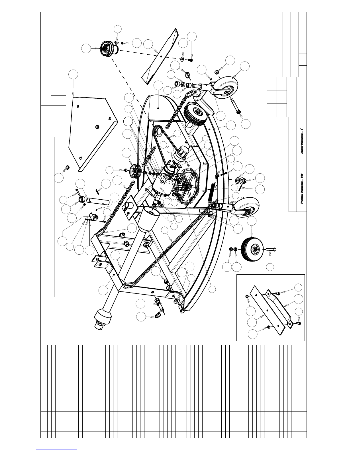
Fence Mower, FM-30 Complete
SHEET 1 of 1
DESCRIPTION
HARDEE BY
EVH MFG. CO.
LORIS S.C.
R.M.N.
N/A
Manufactured By:
EVH Mfg. Co., LLC
MATERIAL
MODELED
BY
TBB 11/17/16
CHECKED
BY
CKN 11/17/16
Decimal Dim. to Limits Shown All Holes to be +0 -1/32"
Tolerance Unless Otherwise Specified
All Dimensions in Inches Unless Otherwise Specified
Dimensions in [ ] are in Millimeters
REV CHANGE BY DATE ECN
IR INITIAL RELEASE
TBB 11/17/16
---
A
Update Pivot Pin - Changed Design
CKN 10/27/17 1690
A
FM-3000
DWG.
NO.
Item Part
Number Qty. Description
1 10002 6 Hex Bolt, 1/4"-20 X 1" Gr.5 Plated
2 10031 3 Hex Bolt 3/8 x 1 gr.5 plated
3 10034 1 Hex Bolt 3/8" x 2-1/2" gr.5 plated
4 10071 2 Hex Bolt 1/2 x 1 gr.5 plated
5 10073 1 Hex Bolt 1/2 x 2 gr.5 plated
6 10096 2 Hex Bolt 5/8"-11 x 4" gr.5 Plated
7 10111 2 Hex Bolt 3/4"-10 X 2" gr.5 Plated
8 10159 1 LOCKNUT W/NYLON INSERT(1/2" PLATED)
9 10160 4 Lock Nut 5/16" Plated
10 10162 3 3/8" Hex Nut (Gr.5 Plated)
11 10164 1 1/2" Hex Nut (Gr.5 Plated)
12 10165 4 Hex Nut 5/8" plated
13 10166 4 Lock Nut 5/8"-11 plated
14 10168 2 3/4"-10 Locknut (Gr.5 Plated)
15 10173 1 1" Castle Flange Nut
16 10175 4 3/8"-16 Locknut (Gr.5 Plated)
17 10176 2 1/2" Locknut (Gr.5 Plated)
18 10180 6 LOCK WASHER(1/4" PLATED)
19 10184 1 Lockwasher 1/2 plated
20 10185 4 Lockwasher 5/8" Plated
21 10200 6 1/4" Plated Flatwasher
22 10204 4 1/2 Flatwasher (Plated)
23 10206 4 Flatwasher 3/4 plated
24 10207 1 Flatwasher, 1" plated
25 10252 1 Cotter Pin 3/16" X 2" Plated
26 10269 1 Hex Bolt 1/2" X 3 3/4" gr.2 Plated
27 10307 2 Category I Hitch Pin
28 10322 3 1/4" Grease Fitting, 1/4"-28 Threaded
29 10346 2 3 pt. Snap Pin (Lynch Pin)
30 11172 1 40HP GEARBOX
31 11469 1 Retaining Ring
32 15392 2 1/4" - 3 pt. Snap Pin (Lynch Pin)
33 15854 1 Manual Holder
34 15860 2 U-Nut, 1/4"-20
35 16417 2 Hex Nut - 3/4"-10 Thrd Sz, 1-1/16" W, 7/8" H
36 16673 1 1/4"-Coiled Spring Pin-HD
37 16776 1 Spindle, Fence Mower
38 16777 1 PTO Driveshaft - 34"
39 16778 2 Trailing Wheel 9" , Fence Mower
40 16779 2 Trailing Wheel Fork
41 16780 2 1/2" Spacer, Fence Mower
42 16781 4 1" Spacer, Fence Mower
43 16783 1 Bushing - Idler Pulley, Fence Mower
44 16784 1 Idler Pulley (Flat)
45 16785 2 Roller Wheel 8" , Fence Mower
46 16786 1 Caster Wheel 2", Fence Mower
47 16788 1 V Belt FM-30, Fence Mower
48 16789 1 Drive Pulley 12", Fence Mower
49 16790 2 Axle Bolt, Trailing Wheel 9" - Fence Mower
50 16791 1 1/2" Spindle/Blade Bolt (Left Hand) - Replacement
51 16793 1 Spring FM-60, Fence Mower
52 16794 1 Eye Bolt - 3/8" x 6", Fence Mower
53 16795 4 QUICK LINK, 3/16' SCREW
54 16798 2 Knob - Cover, Fence Mower
55 16810 1 Eye Bolt - 3/8" x 5", Fence Mower
56 16812 1 Blade - Medium Cutting - Fence Mower
57 16815 1 Blade - Brush Removal - Fence Mower
58 16816 1 Blade - Dirt Removal - Fence Mower
59 16824 1 Conical Washer Blade - Spindle, Fence Mower
60 FM-0038 1 Deck Cover
61 FM-0080 1 Life Chain - FM-30 (53" Long)
62 FM-0081 1 Lift Chain - FM-30 (37" long)
63 FM-0084 1 Pivot Pin, Swing Arm FM-30
64 FM-0085 1 Pivot Pin Collar
65 FM-1005 1 Swing Arm Weldment - FM30
66 FM-1016 1 Base Frame Weldment
67 FM-1018 1 A Frame Weldment
Options: Blades
Fence Mower - FM-30 Complete
Hidden underneath
Plate
1
2
5
6
8
9
11
12
13
14
15
18
19
20
21
22
23
24
26
27
28
29
30
32
33
34
35
37
38
39
40
41
42
43
44
45
46
47
48
49
50
54
55
56
60
63
67
42
22
22
22
23
1
7
18
21
25
28
16
31
57
58
59
10
10
4
17
4
17
12
53
61
62
65
66
52
51
10
3
36
64
16
REFERENCE - FM 30 COMPLETE PARTS LIST
9

Revised 11/23/16
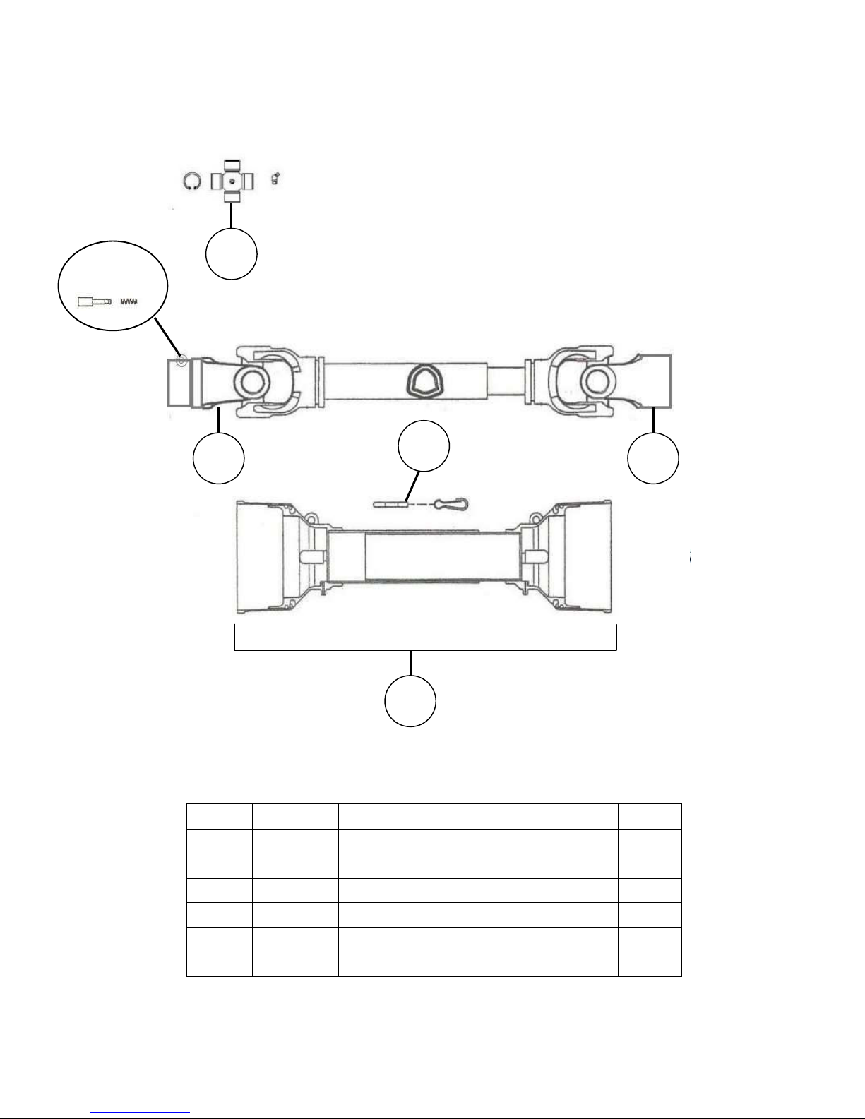
16813
Driveshaft
For FM-30
Key # Part No. Description Qty.
1
15112 Cross Kit (Series 4) 2
2 15579 Pin Kit 1
3 11436 Yoke - Tractor 1
4 15111 Yoke - Spline less 1
5 16725 Chain, Anti-Rotation 2
6 17796 Shield Kit - Complete 1
6
4 3
2
1
5

REV.
DWG.
NO.
FM-6000
B
DWG SIZE
DO NOT
SCALE
Fence Mower, FM-60 Complete
SHEET 1 of 1
DESCRIPTION
HARDEE BY
EVH MFG. CO.
LORIS S.C.
R.M.N.
N/A
Manufactured By:
EVH Mfg. Co., LLC
MATERIAL
MODELED
BY
TBB 11/17/16
CHECKED
BY
CKN 11/17/16
Decimal Dim. to Limits Shown All Holes to be +0 -1/32"
Tolerance Unless Otherwise Specified
All Dimensions in Inches Unless Otherwise Specified
Dimensions in [ ] are in Millimeters
REV CHANGE BY DATE ECN
IR INITIAL RELEASE
TBB 11/17/16
---
A
Update Pivot Pen - Changed Design
CKN 10/27/17 1690
A
FM-6000
DWG.
NO.
Item Part
Number Qty. Description
1 10002 6 Hex Bolt, 1/4"-20 X 1" Gr.5 Plated
2 10031 3 Hex Bolt 3/8 x 1 gr.5 plated
3 10034 1 Hex Bolt 3/8" x 2-1/2" gr.5 plated
4 10071 2 Hex Bolt 1/2 x 1 gr.5 plated
5 10073 1 Hex Bolt 1/2 x 2 gr.5 plated
6 10096 2 Hex Bolt 5/8"-11 x 4" gr.5 Plated
7 10111 2 Hex Bolt 3/4"-10 X 2" gr.5 Plated
8 10159 1 LOCKNUT W/NYLON INSERT(1/2" PLATED)
9 10160 4 Lock Nut 5/16" Plated
10 10162 3 3/8" Hex Nut (Gr.5 Plated)
11 10164 1 1/2" Hex Nut (Gr.5 Plated)
12 10165 4 Hex Nut 5/8" plated
13 10166 4 Lock Nut 5/8"-11 plated
14 10168 2 3/4"-10 Locknut (Gr.5 Plated)
15 10173 1 1" Castle Flange Nut
16 10175 4 3/8"-16 Locknut (Gr.5 Plated)
17 10176 2 1/2" Locknut (Gr.5 Plated)
18 10180 6 LOCK WASHER(1/4" PLATED)
19 10184 1 Lockwasher 1/2 plated
20 10185 4 Lockwasher 5/8" Plated
21 10200 6 1/4" Plated Flatwasher
22 10204 4 1/2 Flatwasher (Plated)
23 10206 4 Flatwasher 3/4 plated
24 10207 1 Flatwasher, 1" plated
25 10252 1 Cotter Pin 3/16" X 2" Plated
26 10269 1 Hex Bolt 1/2" X 3 3/4" gr.2 Plated
27 10307 2 Category I Hitch Pin
28 10322 3 1/4" Grease Fitting, 1/4"-28 Threaded
29 10336 1 Gear Oil [85W-140] - (Not Shown)
30 10346 2 3 pt. Snap Pin (Lynch Pin)
31 11172 1 40HP GEARBOX
32 11469 1 Retaining Ring
33 15392 2 1/4" - 3 pt. Snap Pin (Lynch Pin)
34 15854 1 Manual Holder
35 15860 2 U-Nut, 1/4"-20
36 16417 2 Hex Nut - 3/4"-10 Thrd Sz, 1-1/16" W, 7/8" H
37 16673 1 1/4"-Coiled Spring Pin-HD
38 16776 1 Spindle, Fence Mower
39 16777 1 PTO Driveshaft - 34"
40 16778 2 Trailing Wheel 9" , Fence Mower
41 16779 2 Trailing Wheel Fork
42 16780 2 1/2" Spacer, Fence Mower
43 16781 4 1" Spacer, Fence Mower
44 16783 1 Bushing - Idler Pulley, Fence Mower
45 16784 1 Idler Pulley (Flat)
46 16785 2 Roller Wheel 8" , Fence Mower
47 16786 1 Caster Wheel 2", Fence Mower
48 16787 1 V Belt FM-60, Fence Mower
49 16789 1 Drive Pulley 12", Fence Mower
50 16790 2 Axle Bolt, Trailing Wheel 9" - Fence Mower
51 16791 1 1/2" Spindle/Blade Bolt (Left Hand) - Replacement
52 16792 1 Spring FM-60, Fence Mower
53 16794 1 Eye Bolt - 3/8" x 6", Fence Mower
54 16795 4 QUICK LINK, 3/16' SCREW
55 16798 4 Knob - Cover, Fence Mower
56 16810 1 Eye Bolt - 3/8" x 5", Fence Mower
57 16812 1 Blade - Medium Cutting - Fence Mower
58 16815 1 Blade - Brush Removal - Fence Mower
59 16816 1 Blade - Dirt Removal - Fence Mower
60 16824 1 Conical Washer Blade - Spindle, Fence Mower
61 FM-0039 1 Deck Cover Plate
62 FM-0078 1 Life Chain - FM-60 (65" Long)
63 FM-0079 1 Lift Chain - FM-60 (45" long)
64 FM-0083 1 Pivot Pin, Swing Arm FM-60
65 FM-0085 1 Pivot Pin Collar
66 FM-1009 1 Swing Arm Weldment - FM60
67 FM-1014 1 Base Frame Weldment
68 FM-1018 1 A Frame Weldment
Options: Blades
Fence Mower - FM-60 Complete
Hidden underneath
Plate
1
2
5
6
8
9
11
12
13
14
15
18
19
20
21
22
23
24
26
27
28
30
31
33
34
35
36
38
39
40
41
42
43
44 45
46
47
48
49
50
51
52
56
55
53
57
61
64
66
67
68
43
22 22
22
23
1
7
18
21
25
28
16
10
54
62
63
32
58
59
60
10
10
4
17
4
17
3
65
16
37
11
REFERENCE - FM 60 COMPLETE PARTS LIST
Revised 11/23/16
16777
Driveshaft
For FM-60
Key # Part No. Description Qty.
1
15112 Cross Kit (Series 4) 2
2 15579 Pin Kit 1
3 11436 Yoke - Tractor 1
4 15111 Yoke - Spline less 1
5 16725 Chain, Anti-Rotation 2
6 17796 Shield Kit - Complete 1
6
4 3
2
1
5

REFERENCE - FM-30 and FM-60

Revised 7/25/16
11172
Gearbox
FM-30 and FM-60
(40 H.P. Gearbox 1:1.93 Ratio)
Key #
Part No.
Part Description
Key #
Part No.
Part Description
101
15688
Input seal
111
15664
Pressure relief plug
102
15689
Face plate
112
15753
Gasket
103
15750
Ball bearing
113
16017
Output shaft w/gear
104
15690
Retaining ring
114
15750
Ball bearing
105
15475
Input shaft
115
15695
Retaining ring
106
15545
Input gear
116
15696
Spacer
107
15695
Retaining ring
117
15750
Ball bearing
108
15691
Shim .004
118
15755
Output seal
109
15692
Ball bearing
119
15697
Bottom cap
110
15752
Housing

15
Revised 8/26/15
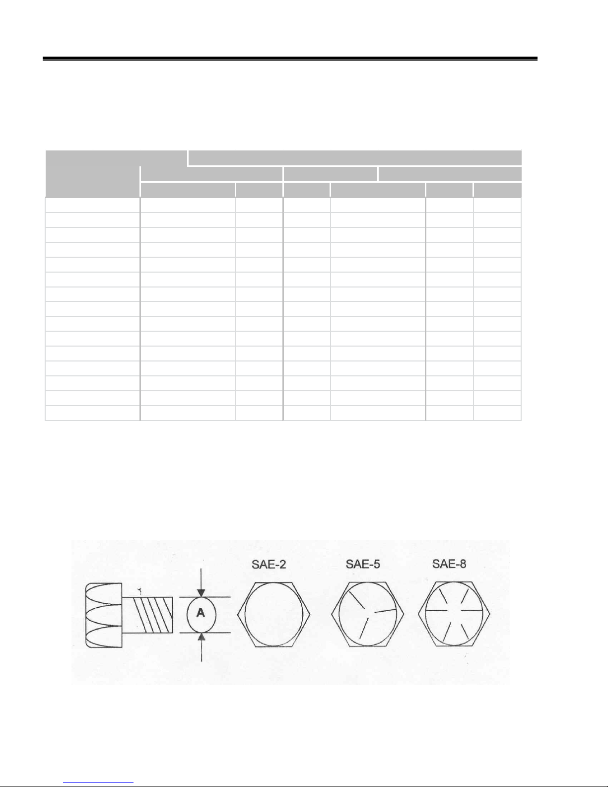
Bolt Torque
Checking Bolt Torque
The tables shown below give correct torque
values for various bolts and capscrews.
Tighten all bolts to the torque specified in the
chart unless otherwise noted. Check
tightness of bolts periodically, using bolt
torque chart as a guide. Replace hardware
with the same strength bolt. Torque figures
indicated are valid for non-greased or non-
oiled threads and heads unless otherwise
specified. Therefore, do not grease or oil
bolts or cap screws unless otherwise
specified in this manual. When using locking
elements, increase torque values by 5%.
NOTE:
Bolt Torques shown are maximum
allowable values for ultimate safe working
strength or external load-carrying capacity.
The bolt torque are not applicable in cases
where bolts are used as a pin-like device,
holding together two or more movable
objects and keeping them from spreading
apart.
–
“Clamping Torque” Being dependent
upon the application of the bolt.
-
Torque value for bolts and cap
screws are
identified by their head markings.
See Page 16
Torque Specifications for Coarse Threads
Bolt Torque Coarse Thread
N.m LB-FT LB-FT N.m
8 9 12 17
13 19 27 36
27 33 45 63
41 53 75 100
61 80 115 155
95 115 165 220
128 160 220 305
225 290 400 540
230 420 650 880
345 630 970 1320
478 794 1287 1737
675 1120 1875 2531
884 1470 2382 3216
1175 1950 3161 4267
500
655
870
354 1072
1512
1985
2632
1” - 8 225 850
1 1/8" - 7
1 1/4" - 7
1 3/8" - 6
1 1/2" - 6
3/4” - 10 165 390
7/8” - 9 170 570
9/16” - 12 70 155
5/8” - 11 95 215
7/16” - 14 30 72
1/2” - 13 45 110
5/16” - 18 10 25
3/8” - 16 20 45
“A” LB-FT N.m
1/4” - 20 612
Diameter SAE-2 SAE-5 SAE-8
See page 20 for
Torque Specifications
for
Fine Threads
and
Head Markings
16
Revised 8/26/15
Torque Specifications for Fine Threads
Bolt Torque Fine Thread
N.m LB-FT LB-FT N.m
810 14 19
16 19 27 36
31 35 49 66
49 55 78 105
74 85 120 162
108 122 172 232
148 170 240 324
270 297 420 567
243 474 668 402
370 705 995 1343
378 721 1019 1376
536 890 1444 1950
747 1241 2012 2716
1007 1672 2712 3661
1322 2194 3557 4802
1"-14 280 973
1 3/8" - 12 746 2257
1 1/2" - 12 979 2962
1 1/8" - 12 397 1201
1 1/4" - 12 553 1675
7/8” -14 180 640
1” - 12 274 952
5/8” - 18 110 230
3/4” - 16 200 400
1/2” - 20 55 115
9/16” - 18 80 165
3/8” - 24 22 47
7/16” - 20 36 74
1/4” - 28 614
5/16” - 24 12 26
Diameter SAE-2 SAE-5 SAE-8
“A” LB-FT N.m
Head Markings
This manual suits for next models
1
Table of contents
Popular Farm Equipment manuals by other brands

BROWN
BROWN 2000 Series Owner's/operator's manual

DuraTech Industries
DuraTech Industries HAYBUSTER CMF-830 Operating Instructions and Parts Reference

Chore-Time
Chore-Time 108 FLEX-AUGER Installation instruction

Swisher
Swisher QuadBoss QBRC11544 owner's manual

T.I.P.
T.I.P. GS-48 Operator instructions

Agria
Agria Taifun 5900 Series Translation of the original operating instructions


