Fender PASSPORT SR6300 User manual

SR6300 / SR8500 Powered Mixers®™
(These are the model name for warranty claims)
Fender® Musical Instruments Corp. 8860 East Chaparral Road Suite 100 Scottsdale, AZ 85250
p/n 0716200000 (120V)
p/n 0718500000 (120V)
SERVICE MANUAL
CONTENTS:
Notices .............................. 2
Specifications SR6300...... 3
Specifications SR8500...... 4
Service Notes.................... 5
Circuit Description............. 6
Parts Lists ......................... 7
Service Diagrams.............. 9

SR6300 / SR8500 Powered Mixers®™
(These are the model name for warranty claims)
2
August, 2004
IMPORTANT NOTICE
•Copyright © 2002 FMIC. All rights reserved. All
information contained herein is CONFIDENTIAL
and PROPRIETARY and is the property of
Fender® Musical Instruments Corporation. It is
not to be sold or assigned to another party and is
disclosed soley for use by Fender Authorized Ser-
vice Centers for purposes of product service and
maintenance. All information is not to be dis-
closed to others without the expressed permission
of Fender® Musical Instruments Corporation. All
specifications are subject to change without no-
tice. This information and any copies produced
electronically or otherwise must be surrendered
upon demand of Fender Musical Instruments Cor-
poration.
•Parts marked with two asterisks (**) indicate the
required use of that specific part. This is neces-
sary for RELIABILITY and SAFETY requirements.
DO NOT USE A SUBSTITUTE!
PARTS LIST CODES
The description codes used in the itemized Parts Lists are defined below:
CAPACITOR CODES
CAP AE = Aluminum Electrolytic
CAP CA = Ceramic Axial
CAP CD = Ceramic Disk
CAP MPF = Metalized Polyester Film
CAP MY = Mylar
CAP PFF = Polyester Film/Foil
RESISTOR CODES
RES CC = Carbon Comp
RES CF = Carbon Film
RES FP = Flame Proof
RES MF = Metal Film
RES WW = Wire Wound
HARDWARE CODES
BLX = Black Oxide
CR = Chrome Plated
HWH = Hex Washer Head
M = Machine Screw
NI = Nickel Plated
OHP = Oval Head Phillips
PB = Particle Board
PHP = Pan Head Phillips
PHPS = Pan Head Phillips Sems
SMA = Sheet Metal "A" Point
SMB = Sheet Metal "B" Point
SS = Stainless Steel
TF = Thread Forming
ZI = Zinc Plated

SR6300 / SR8500 Powered Mixers®™
(These are the model name for warranty claims)
3
SPECIFICATIONS
! " #$
! " #% &
' ( ! " #) $
( ! " #$ *
( ! " #) +
( ! " #, $
( - ! " #.
! " # / *
0
/ 1
! " # !
) 1 2 3 $ %
4 1 5 6 4 1 &
5 4 1 &
) 1 4 &
1 7 1 ' ()
8 ! 9 *
& *
8 1 *
& 9 + * & "
Product specifications are subject to change without notice

SR6300 / SR8500 Powered Mixers®™
(These are the model name for warranty claims)
4
SPECIFICATIONS
: ( :
! " #$
! " #% &
' ( ! " #) $
( ! " #$ *
( ! " #) +
( ! " #, $
( - ! " #.
! " # / *
0
/ 1
! " # !
) 1 2 3 $ %
4 1 5 6 4 1 &
5 4 1 &
) 1 4 &
1 7 1 ' ()
8 ! 9 *
& *
8 1 *
& 9 + * & "
Product specifications are subject to change without notice

SR6300 / SR8500 Powered Mixers®™
(These are the model name for warranty claims)
5
SERVICE NOTES
FRONT PANEL REMOVAL is accomplished by
removing the 6 screws from the front. It helps to
remove the “PROGRAMS” and “MAIN MAS-
TER” knobs for leverage to pull the panel from
the chassis. Clip the wire tie and remove the
two connectors (CON5 + CON6) to completely
remove the front panel. Ensure that all wires
are re-attached onto wire tie point to prevent a
safety hazard.
REAR PANEL REMOVAL is accomplished by
first removing the front panel as in # 1. There
are 6 screws in the rear panel that must be re-
moved; after which the rear panel including
power supply and power amplifier can be re-
moved.
EFFECTS board is permanently connected to
the main mix board (NOT the input section, an
additional board on the front panel). The effects
board is part of the main mix module. To re-
move this module, remove the knobs, nuts and
washers from the “PROGRAMS” and “MAIN
MASTER” controls. There are 5 connectors on
the board that must be disconnected for full re-
moval of effects and main mixer section.
PCB REMOVAL is generally not necessary
since part replacement is done at the module
level only.
POWER AMPLIFIER MODULE REMOVAL is
accomplished by removing the screws on the 4
corners of the heatsink (which is part of the
module). Remove connectors from CON1,
CON2, CON7 and DC FAN.
MODULE EXCHANGE POLICY
If a failure due to one of the modules is
detected, please contact the Fender® Dealer
Customer Service Department to order the
complete Module Assembly.

SR6300/SR8500 Parts List
Part Number Description
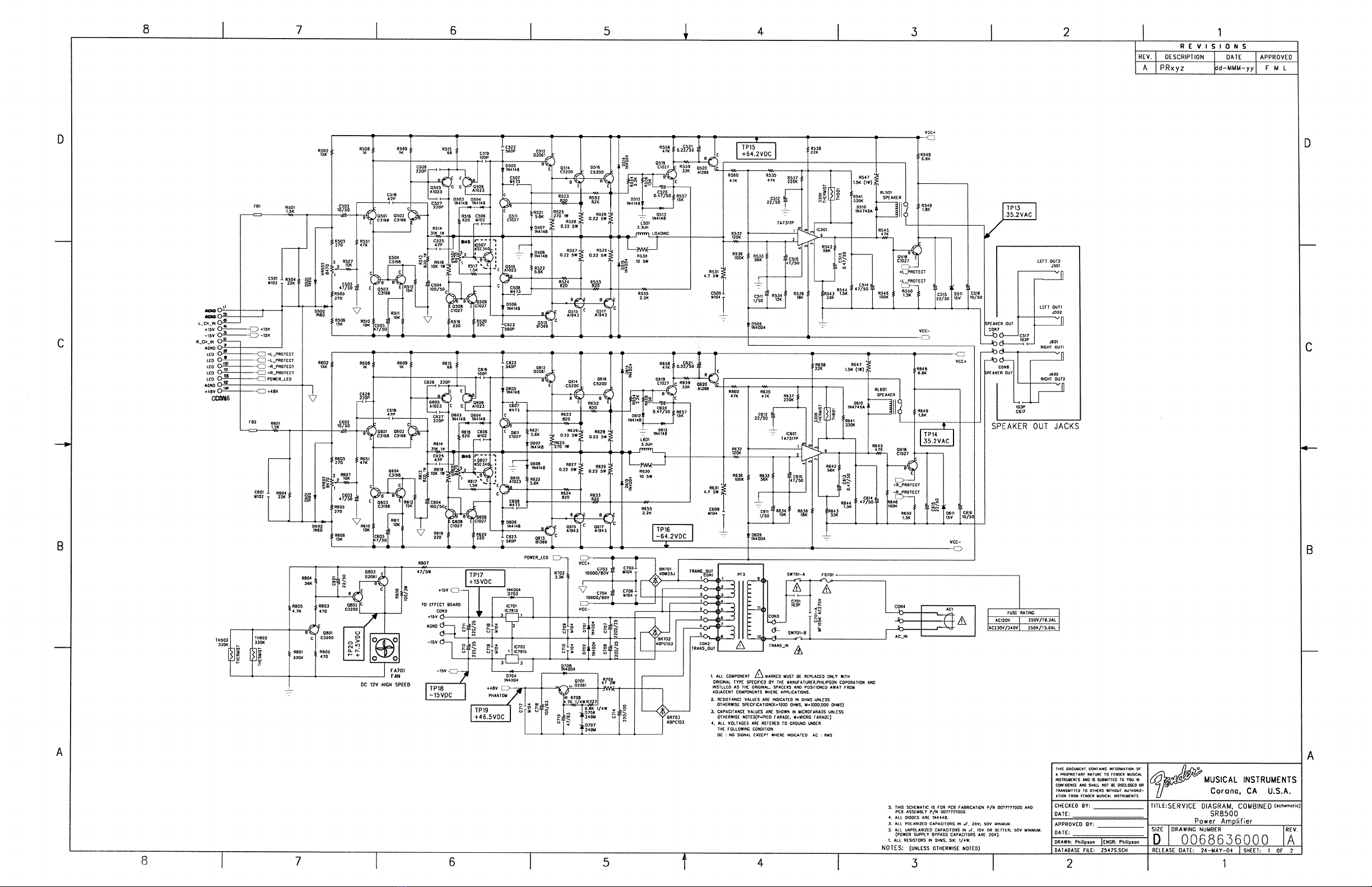
0069912000 Power Amp Module, SR6300
0069913000 Power Amp Module, SR8500
0069914000 Transformer, 120V, SR6300
0069915000 Transformer, 230V, SR6300
0069916000 Transformer, 120V, SR8500
0069917000 Transformer, 230V, SR8500
0069918000 Cooling Fan, SR6300
0069919000 Cooling Fan, SR8500
0069920000 Speaker Output Board, SR Mixers
0069921000 DFX Board, SR Mixers
0069922000 Front Panel Assy, SR6300
0069923000 Front Panel Assy, SR8500
0069924000 Chassis, SR Mixers
0069925000 Knob, Grey Tip, SR Mixers
0069926000 Knob, Red Tip, SR Mixers
0069927000 Knob Green Tip, SR Mixers
0069928000 Knob Blue Tip, SR Mixers
0069929000 Knob, Grey, Phantom Pwr, SR Mixers
0069930000 Knob, Red, DSP, SR Mixers
0069931000 IEC Socket, 120V, SR6300
0069932000 IEC Socket, 120V, SR8500
0069933000 IEC Socket, 230V, SR6300
0069934000 IEC Socket, 230V, SR8500
0069935000 Rubber Feet w/screws, SR Mixers
0069936000 Corner, w/screws, SR Mixers
0069937000 Strap Handle w/cover/scews, SR Mixers
0069938000 Pot, Channel Pan, SR Mixers
0069939000 Pot, Channel Level, SR Mixers
0069940000 Pot, Channel EFX/Mon, SR Mixers
0069941000 Pot, Channel EQ/lo/mid/high, SR Mixers
0069942000 Pot, Master EFX/Aux/Tape, SR Mixers
0069943000 Pot, Master Mon out/L/R, SR Mixers
0069944000 Pot, Main Master, SR Mixers
0069945000 Switch, EFX on/off, SR Mixers
0069946000 Switch, Level Meter Mode, SR Mixers
0069947000 Switch, Phantom Pwr, SR Mixers
0069948000 Switch, System Mode, SR Mixers
0069949000 Jack, TRS, all exept spkr, SR Mixers
0069950000 Jack, XLR, SR Mixers
0069951000 Jack, RCA, SR Mixers
0069952000 Jack, TRS, speaker out, SR Mixers

SR6300 / SR8500 Powered Mixers®™
(These are the model name for warranty claims)
6
CIRCUIT DESCRIPTION
This section provides concise information
about new or unusual circuitry designs
incorporated into the mixer. The purpose is to
aid the service technician by providing insight
into the design areas most likely to become
obstacles in troubleshooting. Information is
focused for its effective use while maintaining
the security of Fender® proprietary information
wherever possible.
FRONT PANEL MIXER SECTION
The mixer section is mainly made of operational
amplifiers and gain stage and therefore requires
only a brief description. The mixer section
consists of 6 or 8 Mic and line inputs with
volume, EQ and pan controls. There are also
monitor and effects bus levels on each channel.
Line inputs can be operated as either balanced
or unbalanced. There is a gain selection switch
(0dB / -20dB) on the front panel for each
channel. Each channel is routed to one of 4
main mixer busses (Left, Right, Monitor and
Effects). The “Main” bus is a mono sum of the
left and right busses. There are many access
points to each bus (tape in/out, aux in etc.) that
are best described in the user’s manual block
diagram.
POWER AMPLIFIER
The power amplifier is a standard class AB
stereo 150 Watt per side amplifier. Note that the
program material sent to the amplifier is switch-
able between Left and Right, Main and Monitor,
and Bridged. Bridge mode level is controlled by
the left volume control.
POWER SUPPLY
The power supply is located on the power
amplifier board.
DIGITAL EFFECTS
The effects are located on a permanently affixed
daughter board on the front panel. This module
converts the effects bus to digital audio,
processes it with the selected effect, and
converts it back to analog audio to later be
mixed onto one of the main channels.
.


This manual suits for next models
1
Table of contents
Other Fender Music Mixer manuals

Fender
Fender 3106 User manual

Fender
Fender SR-6520PD User manual

Fender
Fender Music Mixer User manual

Fender
Fender SR-6520 User manual

Fender
Fender MX-5200 User manual

Fender
Fender SR6325 User manual

Fender
Fender LX-1504 User manual

Fender
Fender PASSPORT SR8500 User manual

Fender
Fender PX-2208 User manual

Fender
Fender MX 5224 User manual