Ferm FIW-500 User manual

PL
RU
EL
Pneumatic imPact
wrench
ATM1043
www.ferm.com
50
EN
DE
NL
FR
ES
PT
IT
SV
FI
NO
DA
HU
CS
SL
09
© 2010 Ferm B.V. 1012-13

2
Fig. C
Fig. B
Fig. A

3
Fig. F Fig. G
Fig. D Fig. E

EN
4
By doing so you now have an excellent product,
delivered by one of Europeís leading suppliers.
All products delivered to you by Ferm are
manufactured according to the highest standards
of performance and safety. As part of our
philosophy we also provide an excellent customer
service, backed by our comprehensive Warranty.
We hope you will enjoy using this product for
many years to come.
The numbers in the text refer to the diagrams
on pages 2-3.
Read the operating instructions
carefully before using this device.
Familiarize yourself with its functions
and basic operation. Service the device
as per the instructions to ensure that it
always functions properly. The
operating instructions and the
accompanying documentation must be
kept in the vicinity of the device.
Your impact wrench has been designed for firmly
tightening and loosening fasteners.
1. Machine information
2. Safety instructions
3. Mounting accessories
4. Operation
5. Service & maintenance
1 Impact wrench
10 Air sockets, 9,10,11,13,14,17,19,22,24 and
27 mm
1 5” Extension bar
1 Oil pot
1 Hex wrench
1 Nipple
1 Mini oiler
1 Instruction manual
1 Safety instruction
1 Warranty card
Check the appliance, any loose parts and
accessories for damage caused during transport.
No load speed 7000/min
Max. operating pressure 6.3 bar
Air consumption 228 l/min (8 cfm)
Air inlet 1/4” - 3/8”
Bolt size capacity 16 mm (5/8”)
Max. torque 310 Nm
Weight 2.2 kg
Lpa (sound pressure) 84.4 + 3 dB(A)
Lwa (acoustic power) 95.4 + 3 dB(A)
Vibration 2.6 + 1.5 m/s2
The vibration emission level stated in this
instruction manual has been measured in
accordance with a standardised test given in
EN 60745; it may be used to compare one tool
with another and as a preliminary assessment of
exposure to vibration when using the tool for the
applications mentioned
- using the tool for different applications, or with
different or poorly maintainted accessories,
may significantly increase the exposure level
- the times when the tool is switched off or when
it is running but not actually doing the job, may
signifi cantly reduce the exposure level
Protect yourself against the effects of vibration by
maintaining the tool and its accessories, keeping your
hands warm, and organizing your work patterns
Fig. A
1. Trigger switch
2. Impact force adjusting knob
3. Air hose connection
4. Accessory holder
5. Forward/reverse switch
Denotes risk of personal injury, loss of life
or damage to the tool in case of non-obser-
vance of the instructions in this manual.

EN
5
Wear ear and eye protection
• Avoid too high pressure
• Keep bystanders and pets away
• Children and animals should be kept far away
from the area of operation of the machine.
• If the compressor is no longer in use, always
take the plug out of the plug socket.
• Always make sure that compressed-air hoses
are used for compressed air and which are
characterized by a maximum pressure
adjusted to that of the compressor. Do not try
to repair the hose if it is damaged.
• Preferably wear safety glasses.
• Do not use the tool in a work area where
stairs, ladders or scaffolding are involved.
• Use accessories with adequate speed rating.
• Never aim the air flow at people or animals.
• Be cautious when using compressed air.
• Only use clean and dry compressed air as a
power source for the tool. Never use oxygen
or a combustible gas.
• Do not exceed maximum operating pressure.
• Keep the tool clean. Do not use any
aggressive or alcohol-based cleaner.
• Never use gasoline or other flammable liquids
to clean the tool. Vapours in the tool will ignite
by a spark and cause the tool to explode.
• Disconnect the tool from the air supply before
troubleshooting or servicing, or during non-
operation.
• Only carry the tool at the grip and never with
the trigger actuated.
• Never carry the tool by the air hose or pull the
air hose to move the tool.
Fig. B
• Wrap a piece of sealing tape around the
connecting piece (7) of the air hose.
• Fit the connecting piece of the air hose into
the connection (3).
• Check whether the air hose is connected
properly.
Fig. C & D
• Fit a socket onto the accessory holder (4).
• Firmly press the socket onto the accessory
holder.
Fig. E & F
• Turn the adjusting knob (2) counterclockwise
to increase the impact force.
• Turn the adjusting knob clockwise to reduce
the impact force.
1 - 190 Nm
2 - 220 Nm
3 - 260 Nm
4 - 310 Nm
Fig. A
• Push the forward/reverse switch (6) forward
for clockwise rotation.
• Push the forward/reverse switch backward for
counterclockwise rotation.
• Tighten the screw.
• Check whether the trigger can move freely.
• Make sure that the tool is lubricated before
connecting it to compressed air.
• Check if the air hose is correctly fitted.
• Set the air pressure to a value within the
allowable operating pressure.
• Only keep your finger on the trigger at the
moment of starting the tool.
• To switch on the tool, press the trigger switch (1).
• To switch off the tool, release the trigger
switch.
Fig. A, C & D
• Fit a required socket.
• Select the direction of rotation.
• Place the tool on the fastener.
• Switch on the tool.
• If necessary, adjust the impact force.

DE
6
The machine does not require any special
maintenance. Regulary check the tool for
possible damages
Fig. G
Pneumatic tools should be lubricated frequently.
• Mount an in-line oiler between the tool and the
air hose.
• If no in-line oiler is installed, insert a few drops
of oil into the air hose connection before use.
Fig. G
The impact mechanism must be lubricated on a
daily basis.
• Remove the screw (12) from the oil filling
point (13).
• Insert a few drops of oil into the mechanism.
• Replace the screw and tighten it.
Should a fault occur, e.g. after wear of a part,
please contact the service address on the
warranty card. In the back of this manual you find
an exploded view showing the parts that can be
ordered.
To prevent damage during transport, the
appliance is delivered in a solid packaging which
consists largely of reusable material. Therefore
please make use of options for recycling the
packaging.
The guarantee conditions can be found on the
separately enclosed guarantee card.
The product and the user manual are subject to
change. Specifications can be changed without
further notice.
Sie besitzen nun ein hervorragendes Produkt von
einem führenden europäischen Lieferanten.
Alle Ferm-Produkte werden nach höchsten
Leistungs- und Sicherheitsstandards gefertigt.
Gemäß unserer Philosophie bieten wir Ihnen
einen exzellenten Kundenservice sowie eine
vollständige Garantie auf unsere Produkte.
An diesem Produkt werden Sie noch viele Jahre
Ihre Freude haben.
Die Ziffern im nachstehenden Text verweisen
auf die Abbildungen auf Seite 2-3.
Lesen Sie diese Bedienungsanleitung
aufmerksam, bevor Sie die Maschine in
Betrieb nehmen. Machen Sie sich mit
der Funktionsweise und der Bedienung
vertraut. Warten Sie die Maschine
entsprechend der Anweisungen, damit
sie immer einwandfrei funktioniert. Die
Betriebsanleitung und die dazugehörige
Dokumentation müssen in der Nähe der
Maschine aufbewahrt werden.
Ihr Druckluftwerkzeugsatz wurde zum Festdrehen
und entfernen von Muttern und Schrauben
konstruiert.
1. Technische Daten
2. Sicherheitsvorschriften
3. Montage des zubehörs
4. Bedienung
5. Wartung und Pflege
1 Druckluftwerkzeugsatz
10 Druckluft-Steckschlüsseleinsätze
9,10,11,13,14,17,19,22,24 und 27 mm
1 5” Verlängerung
1 Ölkanne
1 Sechskant-Stiftschlüssel
1 Nippel
1 Mini-Öler
1 Bedienungsanleitung
1 Sicherheitsvorschriften
1 Garantiekarte

DE
7
Überprüfen Sie die Maschine, lose Teile und
Zubehör auf Transportschäden.
Leerlaufdrehzahl 7000/min
Max. Betriebsdruck 6,3 bar
Luftverbrauch 228 L/min
Lufteinlass 1/4” 3/8” (8 cfm)
Max. Stift-/Klammernlänge 16 mm (5/8”)
Max. Drehmoment 310 Nm
Gewicht 2.2 kg
Lpa (Schalldruckpegel) 84.4 + 3 dB(A)
Lwa (Schallleistungspegel) 95.4 + 3 dB(A)
Vibration 2.6 + 1.5 m/s2
Die im dieser Bedienungsanleitung angegebene
Vibrationsemissionsstufe wurde mit einem
standardisierten Test gemäß EN 60745
gemessen; Sie kann verwendet werden, um ein
Werkzeug mit einem anderen zu vergleichen und
als vorläufige Beurteilung der Vibrationsexposition
bei Verwendung des Werkzeugs für die
angegebenen Anwendungszwecke
- die Verwendung des Werkzeugs für andere
Anwendungen oder mit anderem oder
schlecht gewartetem Zubehör kann die
Expositionsstufe erheblich erhöhen
- Zeiten, zu denen das Werkzeug
ausgeschaltet ist, oder wenn es läuft aber
eigentlich nicht eingesetzt wird, können die
Expositionsstufe erheblich verringern
Schützen Sie sich vor den Auswirkungen der
Vibration durch Wartung des Werkzeugs und
des Zubehörs, halten Sie Ihre Hände warm und
organisieren Sie Ihren Arbeitsablauf
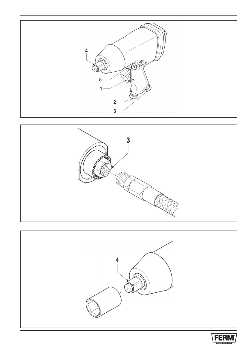
Abb. A
1. Auslöseschalter
2 . Einstellknopf für die Schlagzahl
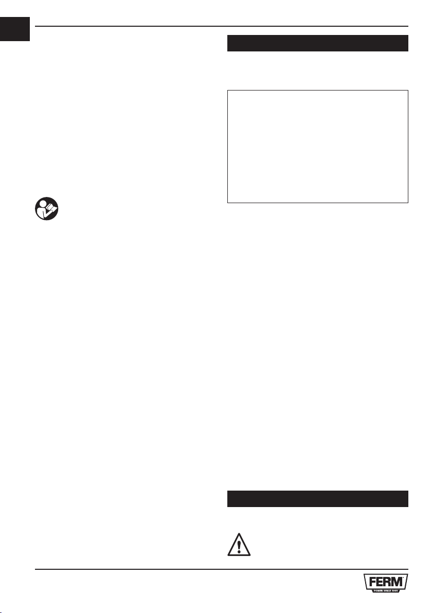
3 . Luftschlauchverbindung
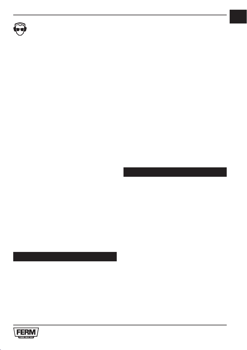
4 . Zubehörhalter
5 . Linkslauf-/Rechtslauf-Umschalter
Lebens- und Verletzungsgefahr und
Gefahr von Beschädigungen am Gerät
bei Nichteinhaltung der Sicherheits-
vorschriften in dieser Anleitung.
Schutzbrille und Gehörschutz tragen
• Überdruck vermeiden.
• Den Strahl nie auf Sie selbst oder andere
Personen richten. Dies kann ernsthafte
Verletzungen verursachen.
• Umstehende und Haustiere fernhalten.
• Kinder und Tiere weit vom Funktionsbereich
des Geräts entfernt halten.
• Tragen Sie am besten eine Schutzbrille.
• Verwenden Sie das Werkzeug niemals in
einem Arbeitsbereich mit Treppen, Leitern
oder Gerüsten.
• Verwenden Sie Zubehör mit geeigneter
Drehzahl.
• Richten Sie den Luftstrom niemals auf
Personen oder Tiere.
• Vorsicht beim Umgang mit Druckluft.
• Verwenden Sie zur Speisung des Werkzeugs
ausschließlich saubere und trockene
Druckluft. Verwenden Sie niemals Sauerstoff
oder brennbare Gase.
• Überschreiten Sie niemals den maximalen
Betriebsdruck.
• Halten Sie das Werkzeug sauber. Verwenden
Sie keine aggressiven oder alkoholhaltigen
Reinigungsmittel.
• Verwenden Sie niemals Benzin oder andere
brennbare Flüssigkeiten zur Reinigung des
Werkzeugs. Die Dämpfe im Werkzeug
werden durch Funken gezündet, und das
Werkzeug explodiert.
• Trennen Sie das Werkzeug von der
Luftversorgung, bevor Sie Fehlersucheoder
Servicearbeiten durchführen bzw. wenn das
Werkzeug nicht verwendet wird.
• Tragen Sie das Werkzeug ausschließlich am
Griff und niemals mit betätigtem Auslöser.
• Tragen Sie das Werkzeug niemals am

DE
8
Schlauch, und ziehen Sie niemals am
Schlauch, um das Werkzeug zu bewegen.
Abb. B
• Wickeln Sie ein Dichtungsband um das
Verbindungsstück (7) des Luftschlauchs.
• Befestigen Sie das Verbindungsstück des
Luftschlauchs an der Verbindung (3).
• Vergewissern Sie sich, daß der Luftschlauch
richtig angeschlossen ist.
Abb. C & D
• Befestigen Sie einen Stecker am
Zubehörhalter (4).
• Drücken Sie den Stecker fest in den
Zubehörhalter.
Abb. E & F
• Drehen Sie den Einstellknopf (2) gegen den
Uhrzeigersinn, um die Schlagzahl zu erhöhen.
• Drehen Sie den Einstellknopf im
Uhrzeigersinn, um die Schlagzahl zu
verringern.
1 - 190 Nm
2 - 220 Nm
3 - 260 Nm
4 - 310 Nm
Abb. A
• Drücken Sie den Linkslauf-/Rechtslauf-
Umschalter (6) für eine Drehung im
Uhrzeigersinn nach vorne.
• Drücken Sie den Linkslauf-/Rechtslauf-
Umschalter für eine Drehung im
Gegenuhrzeigersinn zurück.
• Ziehen Sie die Schraube an.
• Prüfen Sie, ob sich der Auslöser frei bewegen
kann.
• Vergewissern Sie sich, daß das Werkzeug
geschmiert ist, bevor Sie es mit der
Druckluftquelle verbinden.
• Stellen Sie sicher, daß der Luftschlauch
richtig angeschlossen ist.
• Stellen Sie den Luftdruck auf einen Wert ein,
der innerhalb des zulässigen Betriebsdrucks
liegt.
• Legen Sie Ihren Finger nur dann auf den
Auslöser, wenn Sie das Werkzeug starten.
• Zum Einschalten des Werkzeugs drücken Sie
den Auslöseschalter (1).
• Zum Ausschalten des Werkzeugs lassen Sie
den Auslöseschalter los.
Abb. A, C & D
• Befestigen eines gewünschten Steckers.
• Auswählen der Drehrichtung.
• Setzen Sie das Werkzeug auf die
Befestigung.
• Schalten Sie das Werkzeug ein.
• Falls erforderlich, stellen Sie die Schlagzahl
ein.
Das Elektrowerkzeug erfordert keine besondere
Wartung. Überprüfen Sie das Werkzeug
regelmäßig auf Beschädigungen.
Abb. G
Druckluftwerkzeuge sollten häufig geschmiert
werden.
• Anbringen eines Druckluftölers zwischen
Werkzeug und Luftschlauch.
• Wird kein Druckluftöler installiert, geben Sie
einige Tropfen Öl vor dem Gebrauch in die
Luftschlauchverbindung.
Abb. G
Der Schlagmechanismus muß täglich geschmiert
werden.
• Entfernen Sie die Schraube (12) von der
Öleinfüllstelle (13).
• Geben Sie einige Tropfen Öl in den

NL
9
Mechanismus.
• Bringen Sie die Schraube wieder an und
ziehen Sie sie an.
Sollte beispielsweise nach Abnutzung eines Teils ein
Fehler auftreten, dann setzen Sie sich bitte mit der
auf der Garantiekarte angegebenen Serviceadresse
in Verbindung. Im hinteren Teil dieser Anleitung
befindet sich eine ausführliche Übersicht über die
Teile, die bestellt werden können.
Um Transportschäden zu verhindern, wird die
Maschine in einer soliden Verpackung geliefert. Die
Verpackung besteht weitgehend aus verwertbarem
Material. Benutzen Sie also die Möglichkeit zum
Recyclen der Verpackung.
Die Garantiebedingungen finden Sie auf der lose
beigefügten Garantiekarte.
Das Produkt und das Benutzerhandbuch können
geändert werden. Die technischen Daten können
ohne Vorankündigung geändert werden.
Hiermee heeft u een uitstekend product
aangeschaft van één van de toonaangevende
Europese distributeurs.
Alle Ferm producten worden gefabriceerd volgens
de hoogste prestatie- en veiligheidsnormen. Deel
van onze filosofie is de uitstekende klantenservice
die wordt ondersteund door onze uitgebreide
garantie.
Wij hopen dat u vele jaren naar tevredenheid
gebruik zult maken van dit product.
De nummers in de nu volgende tekst ver-
wijzen naar de afbeeldingen op pagina 2-3
Voor uw eigen veiligheid en die van
anderen raden wij u aan deze
gebruikershandleiding zorgvuldig door te
lezen, voordat u deze machine in gebruik
neemt. Bewaar deze
gebruikershandleiding en de overige
documentatie bij de machine.
Uw slagsleutel is ontworpen voor het vast- en
losdraaien van bouten en moeren.
1. Technische informatie
2. Veiligheidsvoorschriften
3. Montage van accessoires
4. Bediening
5. Service en onderhoud
1 Slagsleutel
10 Luchtdoppen, 9,10,11,13,14,17,19,22,24 and
27 mm
1 5” Verlengstuk
1 Olietank
1 Inbussleutel
1 Nippel
1 Kleine oliespuit
1 Gebruiksaanwijzing
1 Veiligheidsvoorschriften
1 Garantiekaart
Controleer de machine, losse onderdelen en
accessoires op eventuele transportschade.

NL
10
Onbelast toerental 7000/min
Max. luchtdruk 6,3 bar
Luchtdoorvoer 228 L/min (8 cfm)
Luchttoevoer 1/4” – 3/8”
Maximale boutmaat 16 mm (5/8”)
Max. torsie 310 Nm
Gewicht 2.2 kg
Lpa (geluidsdruk) 84.4 + 3 dB(A)
Lwa (geluidssterkte) 95.4 + 3 dB(A)
Vibratie 2.6 + 1.5 m/s2
Het trillingsemissieniveau, dat in deze
gebruiksaanwijzing wordt vermeld, is gemeten in
overeenstemming met een gestandaardiseerde
test volgens EN 60745; deze mag worden
gebruikt om twee machines met elkaar te
vergelijken en als voorlopige beoordeling van de
blootstelling aan trilling bij gebruik van de machine
voor de vermelde toepassingen
- gebruik van de machine voor andere
toepassingen, of met andere of slecht
onderhouden accessoires, kan het
blootstellingsniveau aanzienlijk verhogen
- wanneer de machine is uitgeschakeld of
wanneer deze loopt maar geen werk verricht,
kan dit het blootstellingsniveau aanzienlijk
reduceren
Bescherm uzelf tegen de gevolgen van
trilling door de machine en de accessoires te
onderhouden, uw handen warm te houden en uw
werkwijze te organiseren
Afb. A
1. Trekker
2 . Instelknop slagsterkte
3 . Aansluiting luchtslang
4 . Accessoirehouder
5 . Links/rechts-omschakelaar
Gevaar voor lichamelijk letsel of
materiële schade.
Draag oog- en oorbescherming
• Voorkom een te hoge druk
• Blaas of spuit nooit in de richting van uzelf of
anderen; dit zou ernstig letsel kunnen
veroorzaken.
• Houd omstanders en huisdieren uit de buurt.
• Kinderen en dieren moeten ver van de
werkingszone van de machine gehouden
worden.
• Draag bij voorkeur een veiligheidsbril.
• Gebruik het apparaat niet in een werkgebied
met trappen, ladders of steigers.
• Gebruik accessoires met adequaat toerental.
• Richt de luchtstroom nooit op mensen of dieren.
• Wees voorzichtig wanneer u perslucht
gebruikt.
• Gebruik alleen schone, droge perslucht als
stroombron voor het apparaat. Gebruik geen
zuurstof of brandbare gassen.
• Overschrijd nooit de maximale werkdruk.
• Houd het apparaat schoon. Gebruik geen
agressief of alcoholbevattend
schoonmaakmiddel.
• Gebruik geen benzine of andere ontvlambare
vloeistoffen om het apparaat te reinigen.
Dampen in het apparaat zullen door een vonk
ontsteken en het apparaat doen ontploffen.
• Koppel het apparaat los van de luchttoevoer
voordat u foutopsporing of
onderhoudswerkzaamheden verricht, of
wanneer de machine niet in gebruik is.
• Draag het apparaat alleen bij de handgreep
en nooit met de vinger aan de trekker.
• Draag het apparaat nooit bij de luchtslang en
trek nooit aan de luchtslang om het
apparaat te verplaatsen.

NL
11
Fig. B
• Wikkel een stuk afdichtingstape om het
aansluitstuk (7) van de luchtslang.
• Breng het aansluitstuk van de luchtslang in de
aansluiting (3).
• Controleer of de luchtslang correct is
aangesloten.
Fig. C & D
• Breng een dopsleutel aan op de
accessoirehouder (4).
• Druk de dopsleutel stevig op de
accessoirehouder.
Fig. E & F
• Draai de afstelknop (2) linksom om de
slagsterkte te vergoten.
• Draai de afstelknop rechtsom om de
slagsterkte te verkleinen.
1 - 190 Nm
2 - 220 Nm
3 - 260 Nm
4 - 310 Nm
Fig. A
• Duw de links/rechts-omschakelaar (6) naar
voren voor draaiing met de klok mee.
• Duw de links/rechts-omschakelaar naar
achteren voor draaiing tegen de klok in.
• Draai de schroef aan.
• Controleer of de trekker vrijuit kan bewegen.
• Zorg ervoor dat het apparaat is gesmeerd
voordat u het aan perslucht aansluit.
• Controleer of de luchtslang correct is
aangebracht.
• Stel de luchtdruk in op een waarde binnen de
toegestane werkdruk.
• Houd uw vinger alleen aan de trekker op het
moment dat u het apparaat start.
• Om het apparaat in te schakelen, drukt u de
trekker (1) in.
• Om het apparaat uit te schakelen, laat u de
trekker los.
Fig. A, C & D
• Plaats de gewenste dopsleutel.
• Selecteer de draairichting.
• Plaats het apparaat op het bevestigingmiddel.
• Schakel het apparaat in.
• Stel indien nodig de slagsterkte in.
De machine vergt geen speciaal onderhoud.
Controleer het apparaat regelmatig op
eventuele beschadigingen.
Fig. G
Luchtdrukgereedschap dient regelmatig te
worden gesmeerd.
• Monteer een doorlopende olieaanvoer tussen
het apparaat en de luchtslang.
• Indien geen doorlopende olieaanvoer is
geïnstalleerd, brengt u voor gebruik een
aantal druppels olie in de
luchtslangaansluiting aan.
Fig. G
Het slagmechanisme dient dagelijks te worden
gesmeerd.
• Verwijder de schroef (12) van het olievulpunt
(13).
• Breng een aantal druppels olie in het
mechanisme aan.
• Breng de schroef weer aan en draai hem vast.
Wanneer er zich een storing voordoet,
bijvoorbeeld bij slijtage van een onderdeel, neem
dan contact op met het onderhoudsadres op de
garantiekaart. Achter in deze handleiding ziet u
een opengewerkte afbeelding van de onderdelen
die besteld kunnen worden.

FR
12
Om transportbeschadiging te voorkomen, wordt
de machine in een stevige verpakking geleverd.
De verpakking is zo veel mogelijk gemaakt van
recyclebaar materiaal. Maak daarom gebruik van
de mogelijkheid om de verpakking te recyclen.
Lees voor de garantievoorwaarden de afzonderlijk
bijgesloten garantiekaart.
Het product en de gebruikershandleiding zijn
onderhevig aan wijzigingen. Specificaties kunnen
zonder opgaaf van redenen worden gewijzigd.
Vous disposez désormais d’un excellent produit,
fourni par un des premiers distributeurs d’Europe.
Tous les produits qui vous sont livrés par Ferm
sont fabriqués selon les standards les plus élevés
en ce qui concerne performances et sécurité et
sont étayés par une garantie totale et un excellent
service après vente.
Nous espérons que vous profiterez pendant de
nombreuses années de ce produit.
Les numeros du texte ci-apres font reference
aux schemas de la page 2-3.
Lisez attentivement ce mode d’emploi
avant la mise en service de l’appareil.
Familiarisez-vous avec le
fonctionnement et la manipulation de
l’appareil. Entretenez l’appareil
conformément aux instructions, afin
qu’il fonctionne parfaitement à chaque
utilisation. Ce mode d’emploi et toute
documentation relative à l’appareil
doivent être conservés près de celui-ci.
Votre visseuse à chocs pour écrous a été conçue
pour desserrer et serrer fermement la visserie.
1. Données de l’apareil
2. Consignes de sécurité
3. Montage des accessoires
4. Utilisation
5. Entretien
1 Visseuse à chocs
10 Prises d’air, 9, 10, 11, 13, 14, 17, 19, 22, 24 et
27 mm
1 Barre d’extension 5”
1 Réservoir d’huile
1 Clé hexagonale
1 Connecteur d’air
1 Mini-huileuse
1 Mode d’emploi
1 Consignes de sécurité
1 Carte de garantie
Vérifiez que la machine, les pièces détachées
et les accessoires n’ont pas été endommagés

FR
13
durant le transport
Vitesse à vide 7000/min
Pression de fonctionnement maxi. 6,3 bar
Consommation d’air 228 L/min (8 cfm)
Admission d’air 1/4 de po -3/8 de po
Taille de boulon 16 mm (5/8 de po)
Couple maxi. 310 Nm
Poids 2.2 kg
Lpa (pression acoustique) 84.4 + 3 dB(A)
Lwa (puissance acoustique) 95.4 + 3 dB(A)
Vibration 2.6 + 1.5 m/s2
Le niveau de vibrations émises indiqué en ce
manuel d’instruction a été mesuré conformément
à l’essai normalisé de la norme EN 60745; il peut
être utilisé pour comparer plusieurs outils et pour
réaliser une évaluation préliminaire de l’exposition
aux vibrations lors de l’utilisation de l’outil pour les
applications mentionnées
- l’utilisation de l’outil dans d’autres
applications, ou avec des accessoires
différents ou mal entretenus, peut
considérablement augmenter le niveau
d’exposition
- la mise hors tension de l’outil et sa non-
utilisation pendant qu’il est allumé peuvent
considérablement réduire le niveau
d’exposition
Protégez-vous contre les effets des vibrations
par un entretien correct de l’outil et de ses
accessoires, en gardant vos mains chaudes et en
structurant vos schémas de travail
Fig. A
1. Interrupteur de mise en marche
2. Bouton de réglage de la force de percussion
3. Raccord du tuyau à air
4 . Support d’accessoires
5 . Sélecteur de rotation gauche/droite
Danger de blessure physique ou de
dommage matériel.
Portez des lunettes de sécurité et des
protège-ouïe
• Évitez les pressions excessives
• Ne dirigez jamais le jet d’air ou le jet de
pulvérisation sur vous-même ou toute autre
personne; ceci peut causer des blessures
graves.
• Gardez à prudente distance les spectateurs et
les animaux.
• Les enfants et les animaux ne doivent pas
entrer dans la zone de fonctionnement de
l’appareil.
• Le port de lunettes de sécurité est recommandé.
• N’utilisez pas l’outil dans une zone de travail
avec des escaliers, des échelles ou des
échafaudages.
• Utilisez des accessoires présentant des
vitesses appropriées.
• Ne pointez jamais l’appareil en direction de
personnes ou d’animaux.
• Soyez prudent lorsque vous utilisez de l’air
comprimé.
• Utilisez uniquement de l’air comprimé propre et
sec comme source d’alimentation de l’outil.
N’utilisez jamais d’oxygène ou de gaz
combustible.
• N’excédez pas la pression maximale de
fonctionnement.
• Maintenez l’outil propre. N’utilisez pas de produits
de nettoyage puissants ou à base d’alcool.
• N’utilisez jamais d’essence ni d’autres liquides
inflammables pour nettoyer l’outil. Toute vapeur
présente dans l’outil pourrait s’enflammer par
une étincelle et faire exploser l’outil.
• Débranchez l’outil de l’alimentation d’air avant
de le réparer ou de l’entretenir, ainsi que lorsqu’il
n’est pas en fonctionnement.
• Transportez l’outil uniquement en le saisissant
par la poignée et jamais avec l’interrupteur

FR
14
enclenché.
• Ne transportez jamais l’outil par le tuyau d’air et
ne tirez pas sur le tuyau pour le déplacer.
Fig. B
• Enroulez du ruban adhésif autour de la pièce
de raccordement (7) du tuyau d’air.
• Enfoncez la pièce de raccordement du tuyau
à air dans le raccord (3).
• Vérifiez si le tuyau à air est correctement
branché.
Fig. C & D
• Montez une douille sur le support
d’accessoires (4).
• Enfoncez fermement la douille sur le support
d’accessoires.
Fig. E & F
• Faites tourner le bouton de réglage (2) dans
le sens inverse des aiguilles d’une montre
pour accroître la force de percussion.
• Faites tourner le bouton de réglage dans le
sens des aiguilles d’une montre pour réduire
la force de percussion.
1 - 190 Nm
2 - 220 Nm
3 - 260 Nm
4 - 310 Nm
Fig. A
• Poussez l’interrupteur de marche avant/
arrière (6) vers l’avant pour une rotation dans
le sens des aiguilles d’une montre.
• Poussez l’interrupteur de marche avant/
arrière vers l’arrière pour une rotation dans le
sens inverse des aiguilles d’une montre.
• Serrez la vis.
• Vérifiez si l’interrupteur bouge librement.
• Vérifiez la lubrification correcte de l’outil avant
de le raccorder à l’air comprimé.
• Vérifiez que le tuyau à air est bien
correctement monté.
• Réglez la pression de l’air dans les limites de
la pression de travail recommandée.
• Maintenez votre doigt sur l’interrupteur
uniquement au démarrage de l’outil.
• Pour mettre l’outil en marche, appuyez sur
l’interrupteur (1).
• Pour arrêter l’outil, relâchez l’interrupteur.
Fig. A, C & D
• Montez la douille requise.
• Sélectionnez le sens de rotation.
• Placez l’outil sur la visserie.
• Allumez l’outil.
• Si nécessaire, réglez la force de percussion.
La machine n’exige pas d’entretien particulier.
Contrôlez régulièrement l’outil quant à la
présence d’éventuels dommages.
Fig. G
Il convient de lubrifier fréquemment les outils
pneumatiques.
• Montez un graisseur en ligne entre l’outil et le
tuyau à air.
• En l’absence de graisseur en ligne, déposez
quelques gouttes d’huile dans le raccord de
tuyau à air avant usage.
Fig. G
Le mécanisme de percussion doit être ubrifié tous
les jours.
• Retirez la vis (12) du point de graissage (13).
• Déposez quelques gouttes d’huile dans le
mécanisme.
• Remettez la vis et serrez-la.
Veuillez vous adresser au centre de service
indiqué sur la carte de garantie en cas d’un

ES
15
dysfonctionnement, par exemple après l’usure
d’une pièce. Vous trouverez, à la fin de ce
manuel, un schéma avec toutes les pièces que
vous pouvez commander.
Pour éviter les dommages liés au transport, la
machine est livré dans un emballage robuste.
L’emballage est autant que possible constitué
de matériau recyclable. Veuillez par conséquent
destiner cet emballage au recyclage.
Pour les conditions de garantie, lisez le certificat
de garantie joint à part.
Le produit et le manuel d‘utilisation sont sujets
à modifications. Les spécifications peuvent
changer sans autre préavis.
Ahora dispone de un producto excelente,
proporcionado por uno de los principales
distribuidores de Europa.
Todos los productos Ferm ofrecen los niveles
más altos de calidad en cuanto a funcionamiento
y seguridad y, como parte de nuestra filosofía,
prestamos un servicio superior de atención al
cliente avalado por nuestro sello de garantía total.
Esperamos que disfrute utilizando este producto
durante muchos años.
Los números contenidos en el texto siguiente
se refieren a las ilustraciones de la página 2-3.
Lea atentamente estas instrucciones de
uso antes de poner el aparato en
funcionamiento. Póngase al corriente
con la forma de funcionamiento y el
manejo. Cuide la máquina de acuerdo
con las instrucciones para que funcione
siempre de forma correcta. Las instruc-
ciones de uso y la correspondiente
documentación deben guardarse en la
proximidad de la máquina.
El atornillador de percusión se ha diseñado para
apretar firmemente y aflojar elementos de fijación.
1. Datos técnicos
2. Normas de seguridad
3. Montaje de los accessorios
4. Manejo
5. Mantenimiento
1 Atornillador de percusión
10 Tomas de aire de 9, 10, 11, 13, 14, 17, 19, 22,
24 y 27 mm
1 Barra de extensión de 5”
1 Depósito de aceite
1 Llave hexagonal
1 Boquilla de acoplamiento
1 Mini-engrasador
1 Manual de instrucciones
1 Prescripciones de seguridad
1 Tarjeta de garantía

ES
16
Compruebe la máquina, las piezas sueltas y
los accesorios para ver si existen daños de
transporte.
Velocidad sin carga 7000/min.
Máx. presión de trabajo 6,3 bar
Consumo de aire 228 L/min. (8 cfm)
Entrada de aire 1/4” – 3/8”
Tamaño del perno 16 mm (5/8”)
Torsión máx. 310 Nm
Peso 2.2 Kg.
LpA (presión acústica) 84.4 + 3 dB (A)
LwA (nivel sonoro) 95.4 + 3 dB (A)
Vibración 2.6 + 1.5 m/s2
El nivel de emisión de vibraciones indicado en
este manual de instrucciones ha sido medido
según una prueba estándar proporcionada en
EN 60745; puede utilizarse para comparar una
herramienta con otra y como valoración preliminar
de la exposición a las vibraciones al utilizar la
herramienta con las aplicaciones mencionadas.
- al utilizarla para distintas aplicaciones o con
accesorios diferentes o con un mantenimiento
defi ciente, podría aumentar de forma notable
el nivel de exposición.
- en las ocasiones en que se apaga la herramienta
o cuando está funcionando pero no está
realizando ningún trabajo, se podría reducir el
nivel de exposición de forma importante.
Protéjase contra los efectos de la vibración
realizando el mantenimiento de la herramienta
y sus accesorios, manteniendo sus manos
calientes y organizando sus patrones de trabajo.
Fig. A
1. Interruptor de gatillo
2. Pomo de ajuste de la fuerza de percusión
3. Conexión de la manguera de aire
4. Porta-accesorio
5. Interruptor de avance/retroceso
Indica peligro de accidente, de muerte o
riesgo de provocar averías en el
aparato en caso de no seguir las
instrucciones de este manual.
Utilice siempre gafas de seguridad y
protección para los oídos.
• Evita la presión demasiado alta.
• No sople o pulverice nunca en dirección a
usted mismo o de otras personas; podría
ocasionar heridas de gravedad.
• Mantenga alejadas a terceras personas y
mascotas.
• Mantenga a los niños y a los animales
retirados del área de funcionamiento del
equipo.
• Utilice gafas de protección.
• No utilice la herramienta en áreas de trabajo
donde haya escalones, escaleras de mano o
andamios.
• Utilice accesorios con una velocidad nominal
adecuada.
• Nunca apunte el flujo de aire hacia personas
ni animales.
• Tome precauciones cuando use aire comprimido.
• Use únicamente aire comprimido limpio yseco
como fuente de energía para la herramienta.
No use nunca oxígeno ni gases combustibles.
• Nosobrepaselapresiónmáximadetrabajo.
• Mantenga la herramienta limpia. No utilice
ningún limpiador agresivo ni con base de
alcohol.
• No use nunca gasolina ni otros líquidos
inflamables para limpiar la herramienta. Los
vapores de la herramienta podrían inflamarse
a causa de una chispa haciéndola explotar.
• Desconecte la herramienta del suministro de
aire antes de cualquier tarea de reparación o
mantenimiento o mientras no esté
funcionando.
• Transporte la herramienta únicamente por el
asa y nunca con el gatillo accionado.
• No sujete nunca la herramienta por la

ES
17
manguera de aire ni tire de la manguera de
aire para desplazar la herramienta.
Fig. B
• Enrolle un pedazo de cinta de aislante
alrededor de la pieza de conexión (7) de la
manguera de aire.
• Coloque la pieza de conexión de la manguera
de aire dentro de la conexión (3).
• Compruebe si la manguera de aire está
adecuadamente conectada.
Fig. C & D
• Coloque un encaje en el portaaccesorios (4).
• Presione firmemente el encaje en el
portaaccesorios.
Fig. E & F
• Gire el pomo de ajuste (2) en el sentido
contrario a las agujas del reloj para aumentar
la fuerza de percusión.
• Gire el pomo de ajuste en el sentido de las
agujas del reloj para reducir la fuerza de
percusión.
1 - 190 Nm
2 - 220 Nm
3 - 260 Nm
4 - 310 Nm
Fig. A
• Empuje el interruptor de avance/retroceso (6)
hacia delante para una rotación en el sentido
de las agujas del reloj.
• Empuje el interruptor de avance/retroceso
hacia atrás para una rotación en el sentido
contrario las agujas del reloj.
• Apriete el tornillo.
• Compruebe si el gatillo puede moverse
libremente.
• Asegúrese de que la herramienta esté
lubricada antes de conectarla al aire
comprimido.
• Compruebe si la manguera de aire está
colocada correctamente.
• Fije la presión de aire a un valor que esté
dentro de la presión de trabajo permitida.
• Mantenga su dedo en el gatillo únicamente en
el momento de arrancar la herramienta.
• Para encender la herramienta, presione el
interruptor de gatillo (1).
• Para apagar la herramienta, suelte el
interruptor de gatillo.
Fig. A, C & D
• Coloque el encaje que necesite.
• Seleccione la dirección de rotación.
• Coloque la herramienta sobre el elemento de
fijación.
• Encienda la herramienta.
• Si fuera necesario ajuste la fuerza de
percusión.
La máquina no requiere ningún mantenimiento
especial. Compruebe regularmente la
herramienta para comprobar si hay sufrido daños.
Fig. G
Las herramientas neumáticas deben lubricarse
con frecuencia.
• Monte un engrasador dentro del conducto
entre la herramienta y la manguera de aire.
• Si no hay instalado un engrasador en el
conducto, ponga unas gotas de aceite dentro
de la conexión de la manguera de aire antes
del uso.
Fig. G
El mecanismo de percusión debe lubricarse a diario.
• Quite el tornillo (12) del punto de llenado de
aceite (13).

PT
18
• Ponga unas gotas de aceite en el mecanismo.
• Vuelva a colocar el tornillo y apriételo.
Si se presenta una avería, por ejemplo, por el
desgaste de una pieza, póngase en contacto con
el proveedor de servicios indicado en la tarjeta de
garantía. En el dorso de este manual encontrará
un amplio resumen de las partes de recambio que
se pueden ordenar.
Para prevenir los daños durante el transporte, el
aparato ha sido embalado. Dicho embalaje está
hecho, en la medida de lo posible, de material
reciclable. Le rogamos, por lo tanto, que recicle
dicho material.
Lea atentamente las condiciones de garantía
indicadas en la tarjeta de garantía que aparece en
este manual de instrucciones.
El producto y el manual de usuario están
sujetos a cambios. Las especificaciones pueden
modificarse sin previo aviso.
Agora possui um produto excelente, fornecido por
um dos principais distribuidores Europeus.
Todos os produtos que lhe são entregues pela
Ferm são fabricados segundo as mais rigorosas
normas de desempenho e segurança, e como
parte da nossa filosofia, disponibilizamos um
excelente serviço ao cliente acompanhado da
nossa garantia total.
Esperamos que goze a utilização deste produto
durante muitos anos.
Os números no texto seguinte correspondem
às figuras da página 2-3.
Leia este manual de instruções com
atenção antes de colocar o aparelho em
funcionamento. Familiarize-se com o
modo de funcionamento e de operação.
Efectue a manutenção ao aparelho de
acordo com as indicações, de forma a
garantir um bom funcionamento. O
manual de instruções e a documen-
tação correspondente devem ser
guardadas perto do aparelho.
A sua chave de impacto foi concebida paraapertar
firmemente e soltar prendedores.
1. Dados da máquina
2. Instruções de segurança
3. Montar acessórios
4. Funcionamiento
5. Manutenção
1 Chave de impacto
10 Soquetes pneumáticos,
9,10,11,13,14,17,19,22,24 e 27 mm
1 Barra de extensão de 5”
1 Recipiente do óleo
1 Chave hexagonal
1 Bocal de lubrificação
1 Mini almotolia
1 Manual de instruções
1 Cartão de garantia
1 Instruções de segurança

PT
19
Verifique a máquina e acessórios para identificar
danos ocorridos no transporte.
Velocidade sem carga 7000/min
Pressão máxima de funcionamento 6,3 bar
Consumo de ar 228 L/min (8 cfm)
Admissão de ar 1/4” – 3/8”
Cap. de tamanho das cavilhas 16 mm (5/8”)
Binário máximo 310 Nm
Peso 2.2 kg
Lpa (pressão sonora) 84.4 + 3 dB(A)
Lwa (potência acústica) 95.4 + 3 dB(A)
Vibração 2.6 + 1.5 m/s2
O nível de emissão de vibrações indicado na
parte posterior deste manual de instruções foi
medido de acordo com um teste normalizado
fornecido na EN 60745; pode ser utilizado para
comparar uma ferramenta com outra e como uma
avaliação preliminar de exposição à vibração
quando utilizar a ferramenta para as aplicações
mencionadas
- utilizar a ferramenta para diferentes
aplicações ou com acessórios diferentes ou
mantidos defi cientemente, pode aumentar
signifi cativamente o nível de exposição
- o número de vezes que a ferramenta é
desligada ou quando estiver a trabalhar sem
fazer nada, pode reduzir signifi cativamente o
nível de exposição
Protejase contra os efeitos da vibração,
mantendo a ferramenta e os acessórios,
mantendo as mãos quentes e organizando os
padrões de trabalho
Fig. A
1. Interruptor do gatilho
2. Parafuso de ajuste da força de impacto
3. Ligação do tubo de ar
4. Suporte para acessórios
5. Interruptor de avanço/recuo
Perigo de ferimentos ou danos no
material.
Use óculos de protecção e protecção
auditiva
• Evite pressão elevada demais
• Nunca sopre ou pulverize na sua direcção ou
na de outros, porque isto pode provocar
ferimentos graves.
• Mantenha pessoas e animais afastados.
• Crianças e animais deverão ser mantidos
afastados da área de operação da máquina.
• De preferência, utilize óculos protectores.
• Não utilize a ferramenta numa área de
trabalho onde existam escadas, escadotes ou
andaimes.
• Utilize acessórios com uma velocidade
adequada.
• Nunca aponte o fluxo de ar a pessoas ou
animais.
• Tenha especial atenção sempre que utilizar ar
comprimido.
• Utilize apenas ar comprimido limpo e seco
como fonte de energia para a ferramenta.
• Nunca utilize oxigénio ou um gás
combustível.
• Não exceda a pressão máxima de
funcionamento.
• Mantenha a ferramenta limpa. Não utilize
materiais de limpeza agressivos ou à base de
álcool.
• Nunca utilize gasolina ou outros líquidos
inflamáveis para limpar a ferramenta. Os
vapores na ferramenta poderão incendiar
com uma faísca e dar origem a que a
ferramenta exploda.
• Desligue a ferramenta do abastecimento de
ar antes de proceder à resolução de
problemas ou reparação, ou durante o
período de não funcionamento.
• Transporte a ferramenta apenas pelo punho e
nunca com o gatilho accionado.

PT
20
• Nunca transporte a ferramenta pelo tubo de
ar nem puxe pelo mesmo para deslocar a
ferramenta.
Fig. B
• Enrole um pedaço de fita vedante à volta da
peça de ligação (7) do tubo de ar.
• Fixe a peça de ligação do tubo de ar à ligação
(3).
• erifique se o tubo de ar está correctamente
ligado.
Fig. C & D
• Fixe uma tomada ao suporte dos acessórios
(4).
• Prima firmemente a tomada contra o suporte
dos acessórios.
Fig. E & F
• Rode o botão de ajuste (2) para a esquerda
para aumentar a força de impacto.
• Rode o botão de ajuste para a direita para
diminuir a força de impacto.
1 - 190 Nm
2 - 220 Nm
3 - 260 Nm
4 - 310 Nm
Fig. A
• Empurre o interruptor de avanço/recuo (6)
para a frente, para rodar para a direita.
• Empurre o interruptor de avanço/recuo para
trás, para rodar para a esquerda.
• Aperte o parafuso.
• Certifique-se de que é possível mover
livremente o gatilho.
• Certifique-se de que a ferramenta foi
lubrificada antes a ligar ao ar comprimido.
• Verifique se o tubo de ar está montado
correctamente.
• Defina a pressão do ar para um valor dentro
da pressão de funcionamento permitida.
• Coloque o dedo no gatilho apenas no
momento de ligar a ferramenta.
• Para ligar a ferramenta, prima o interruptor do
gatilho (1).
• Para desligar a ferramenta, liberte o
interruptor do gatilho.
Fig. A, C & D
• Aplique uma tomada necessária.
• Seleccione a direcção de rotação.
• Coloque a ferramenta sobre o prendedor.
• Ligue a ferramenta.
• Caso seja necessário, ajuste a força de
impacto.
A sua ferramenta não precisa de manutenção
particular. Verifique a ferramenta regularmente
quanto à existência de possíveis danos.
Fig. G
As ferramentas pneumáticas devem ser
lubrificadas com frequência.
• Monte um lubrificador em linha entre a
ferramenta e o tubo de ar.
• Caso não esteja instalado um lubrificador em
linha, aplique algumas gotas de óleo na
ligação do tubo de ar antes de proceder à
utilização da ferramenta.
Fig. G
O mecanismo de impacto deve ser lubrificado
diariamente.
• Retire o parafuso (12) do ponto de
enchimento de óleo (13).
• Aplique algumas gotas de óleo no
mecanismo.
• Recoloque o parafuso e aperte-o.
Se ocorrer alguma falha, por exemplo, devido
Table of contents
Languages:
Other Ferm Impact Driver manuals