-9-
• Reassembly of the hammer assembly
[13]
J-297 base for washer (S)
• Mounting the mechanical parts
2. Mounting the mechanical parts
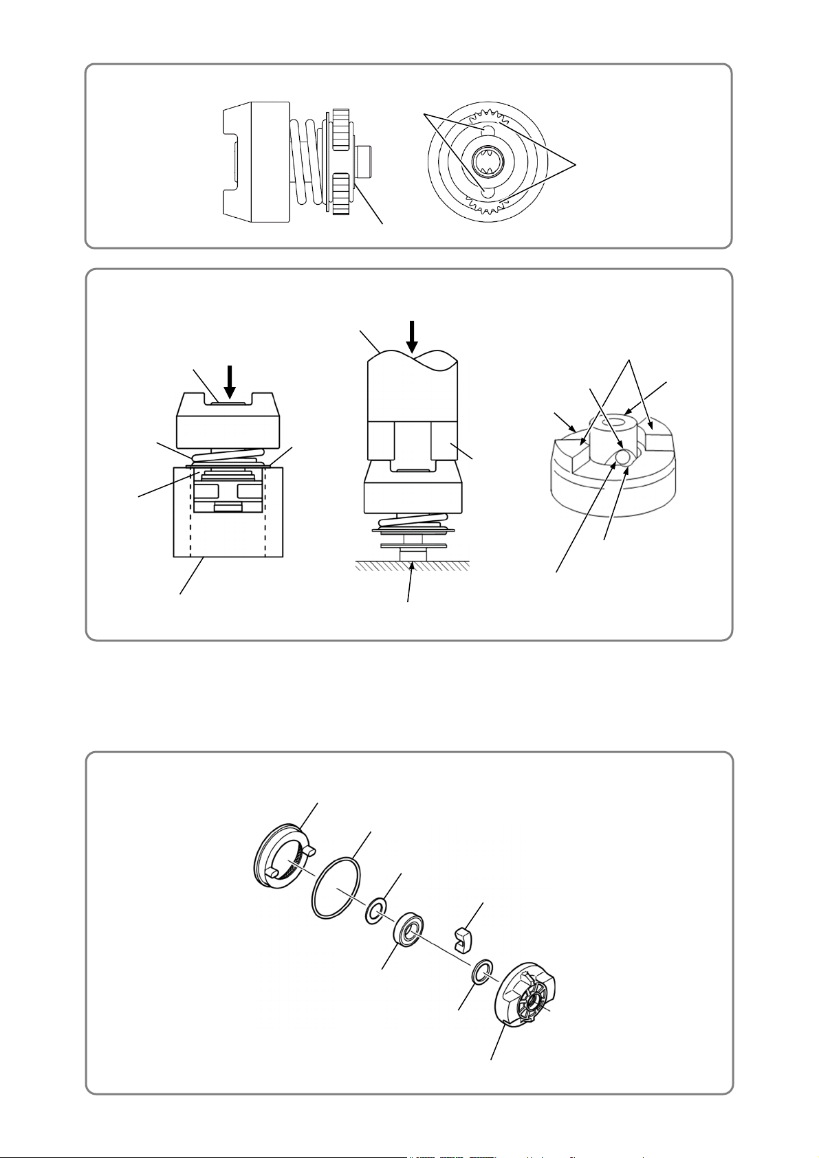
(1) With twenty-eight Steel Balls D3.175 [11] inserted into the Hammer [10], mount Washer (J) [12], Hammer
Spring (J) [13], Washer (S) [14], and the Spindle [18] to the Hammer [10] in this order.
(2) Align the top of the cam groove on the Spindle [18] with the steel ball guide groove on the Hammer [10].
Push down the tab at the tip of the Hammer [10] with a hand press or similar tool to compress Hammer
Spring (J) [13] until it contacts the Spindle [18] and hold it there.
(3) Insert one Steel Ball D5.556 [16] into the steel ball guide groove, then insert another Steel Ball D5.556
[16] into the steel ball guide groove on the other side. Check that the two Steel Balls D5.556 [16] are
properly put in the cam groove. Then release the hand press.
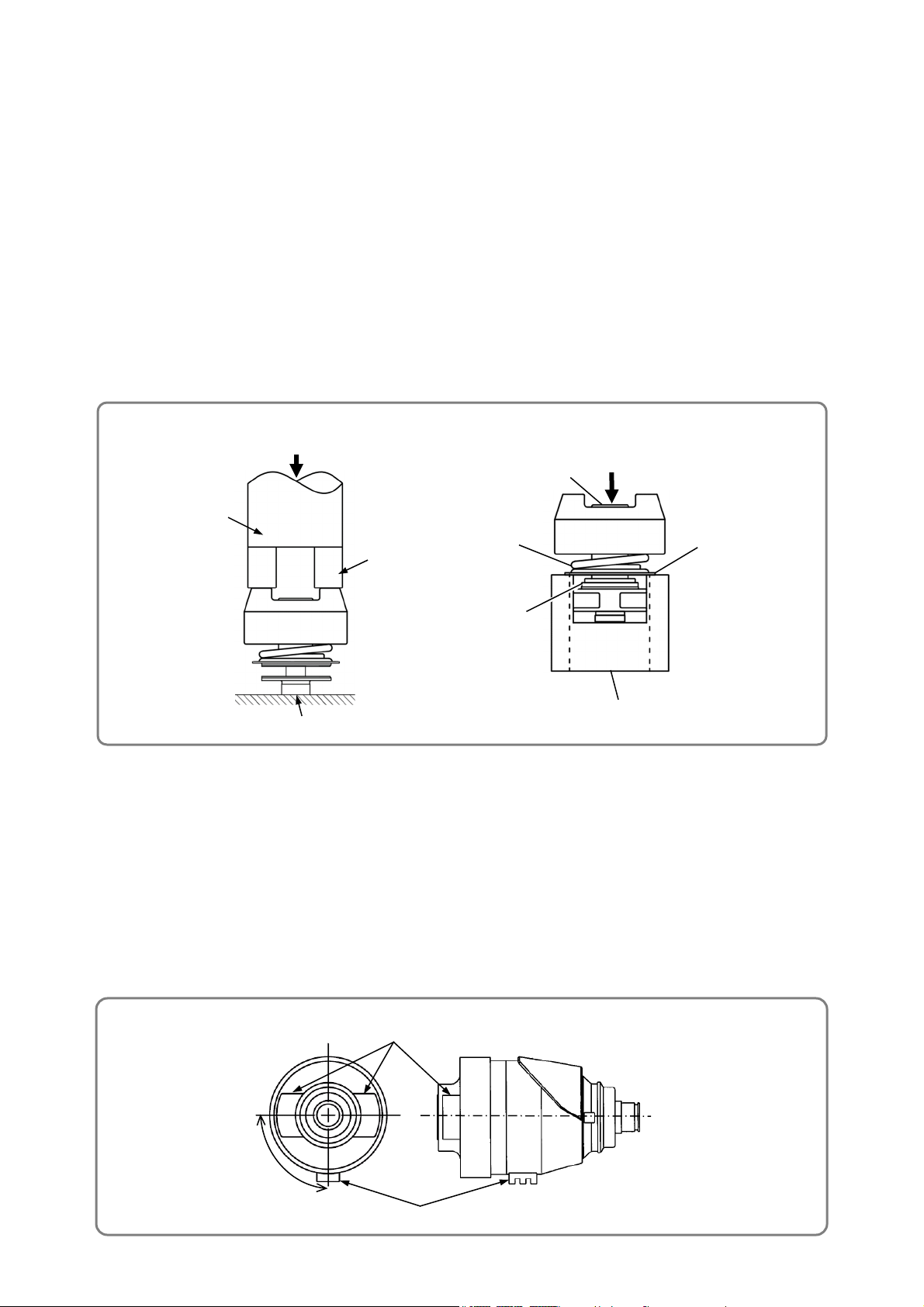
(4) Mount the hammer assembly onto the J-297 base for washer (S) (Code No. 317063). With a hand press,
press down on the top of the Spindle [18] to compress Hammer Spring (J) [13]. In this condition, mount
Stopper (C) [15] onto the spindle shaft facing its convex side upward. Then release the hand press.
(5) Mount the Idle Gear Set (2 pcs.) [17] and two Needle Rollers [19] to the Spindle [18], and insert Washer
(E) [22] to assemble the hammer assembly.
(6) Mount Felt (B) [25] to the Inner Cover [26]. Press-fit the Ball Bearing 6901VV [23] into the Inner Cover
[26]. Mount two Dampers (A) [24] to the Inner Cover [26]. Mount the O-ring (S-42) [21] to Ring Gear (E)
[20]. Mount Ring Gear (E) [20] to the Inner Cover [26] aligning the retaining ribs of Ring Gear (E) [20]
with the concave portions of Dampers (A) [24].
(7) Check that Washer (E) [22] is mounted to the Spindle [18]. Mount the hammer assembly to the Inner
Cover [26] meshing the Idle Gear Set (2 pcs.) [17] with Ring Gear (E) [20] properly.
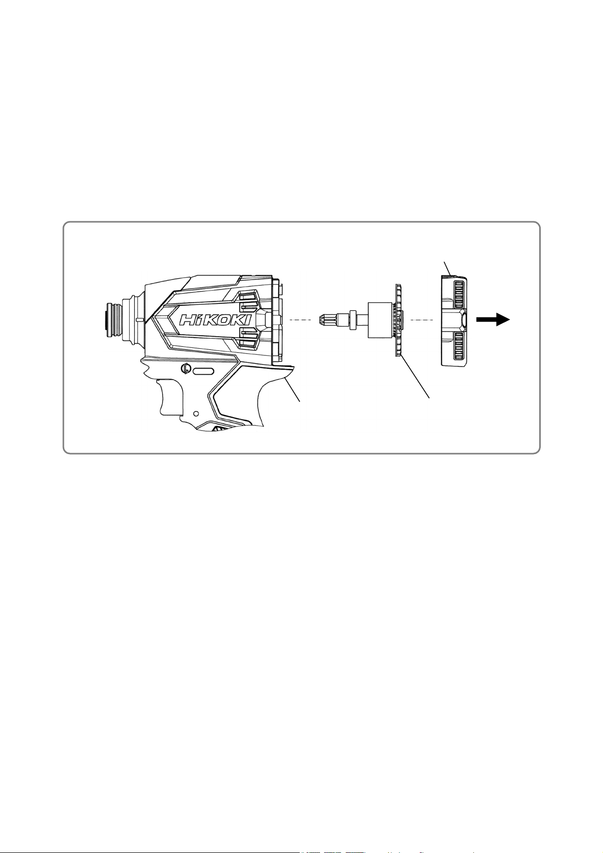
(8) Mount Anvil [9] to the tip of the Spindle [18]. Mount Washer (F) [7] to the Hammer Case [6]. Then mount
the Hammer Case [6].
NOTE: Check that the thick ribs on the Inner Cover [26] are positioned at 90° relative to the
retaining tabs on the Hammer Case [6].
Press down.
End surface of the Spindle [18]
Hand press
[15]
[14]
Press down.
[18]
90°
Retaining tabs on the Hammer Case [6]
Thick ribs on the Inner Cover [26]
Jig (block etc.)