Festo HMP-...-SL Series User manual

%HGLHQXQJVDQOHLWXQJ
6HQVRUOHLVWHIU
/LQHDUPRGXO+03
7\S+036/
2SHUDWLQJLQVWUXFWLRQV
6HQVRUPDQLIROGIRU+03
OLQHDUPRGXOH
W\SH+036/
Einbau und Inbetriebnahme sind nur
durchzuführen von Fachpersonal mit
entsprechender Qualifikation gemäß Be-
dienungsanleitung.
Fitting and commissioning must be car-
ried out only by qualified technicians in
accordance with these operating instruc-
tions.
Es bedeuten:/Symbols:
Warnung
Warning, Caution
Hinweis
Note
Recycling
Recycling
Zubehör
Accessories
395 417
9908a D/GB 1

2SHUDWLQJSDUWVDQG
FRQQHFWLRQV
%HGLHQWHLOHXQG$QVFKOVVH
1
2
3
4
5
6
7
8
9
0
Magnet
Zylinderstift zur Positionierung des
Magnethalters
Magnethalter
Nut für max. 2 Näherungsschalter
Enddeckel
Einfräsung für Kabelabgang
(im Enddeckel des Linearmoduls)
Nut für max. 3 Näherungsschalter
Sensorleiste
Frontdeckel
Kugellaufbahn des Führungsrohrs
zur Winkelausrichtung des
Magnethalters
1
2
3
4
5
6
7
8
9
0
Magnet
Cylinder pin for positioning the
magnet support
Magnet support
Groove for max. 2 prox. switches
End cover
Recess for cable exit
(in end cover of linear module)
Groove for max. 3 prox. switches
Sensor manifold
Front cover
Ball-bearing track of the guide tube
for setting the angle of the magnet
support
123
6
54
7
8
0
9
)LJ
+036/
9908a D/GB 2

)XQNWLRQXQG$QZHQGXQJ
Die Sensorleiste HMP-...-SL ist ein Er-
gänzungsmodul zum pneumatischen Li-
nearmodul HMP-... . Es können bis zu 5
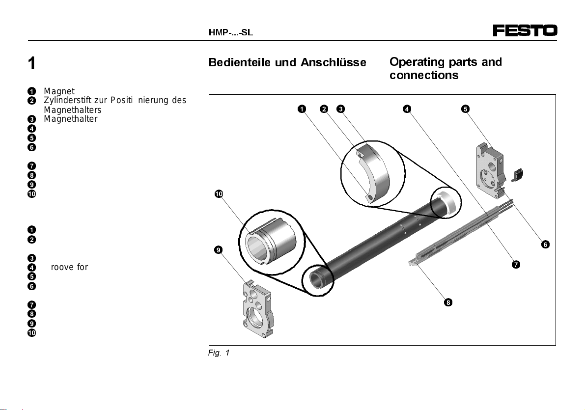
Näherungsschalter in den Nuten
4
und
7
der Sensorleiste plaziert werden. Die
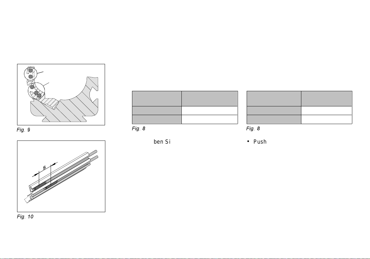
elektrischen Kabel werden durch eine
Profilaussparung am Enddeckel des Li-
nearmoduls nach außen geführt. Dabei
ist die Kabelführung gemäß Fig. 2 zu
beachten.
Die Sensorleiste dient bestimmungsge-
mäß zur Abfrage von Endlagen- und
Zwischenpositionen mit Näherungs-
schaltern vom Typ SME-8-.../SMT-8-... .
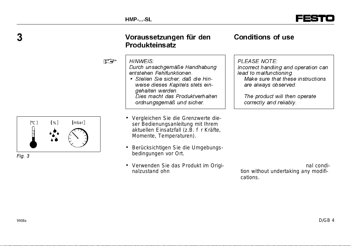
+,1:(,6
6WDUNH0DJQHWIHOGHULQXQPLWWHOEDUHU
1lKHGHV/LQHDUPRGXOV]%EHL
6FKZHLDQODJHQIKUHQ]XHLQHU
'DXHUPDJQHWLVLHUXQJGHUIHUURPDJ
QHWLVFKHQ7HLOH'LH)ROJHLVWHLQH
EOHLEHQGH9HUVFKLHEXQJGHU6FKDOW
SXQNWHGHU1lKHUXQJVVFKDOWHU
•
6WHOOHQ6LHVLFKHUGDVWDUNH
HOHNWURPDJQHWLVFKH6W|UIHOGHUYRP
+03IHUQJHKDOWHQZHUGHQ
]%PLW$EVFKLUPXQJHQDXVHLQHP
7UDIREOHFK
)XQFWLRQDQGDSSOLFDWLRQ
The HMP-...-SL sensor manifold is a
supplementary module to the pneumatic
linear module type HMP-... . Up to 5
proximity switches can be placed in the
sensor grooves
4
and
7
. The electric
cables can be passed out through a re-
cess on the end cover of the linear mo-
dule. Please note the cable routing as
shown in Fig. 2.
The sensor manifold is intended for
scanning both the end and intermediate
positions of the piston in the linear mo-
dule. The proximity switches used are of
type SME-8-.../SMT-8-... .
3/($6(127(
6WURQJPDJQHWLFILHOGVLQWKHLPPHGL
DWHYLFLQLW\RIWKHOLQHDUPRGXOHLH
ZLWKZHOGLQJV\VWHPVFDQOHDGWRFRQ
WLQRXVPDJQHWL]DWLRQRIWKHIHUURPDJ
QHWLFSDUWV7KLVUHVXOWVLQFRQWLQRXV
GLVSODFHPHQWRIWKHVZLWFKLQJSRLQWV
RIWKHSUR[LPLW\VZLWFKHV
•
0DNHVXUHWKHUHIRUHWKDWWKHUHDUH
QRVWURQJILHOGVRIHOHFWURPDJQHWLF
LQWHUIHUHQFHLQWKHYLFLQLW\RIWKH
+03HJE\VFUHHQLQJPDGHRI
WUDQVIRUPHUPDJQHWLFVWHHHO
4
7
)LJ
9908a D/GB 3

9RUDXVVHW]XQJHQIUGHQ
3URGXNWHLQVDW]
+,1:(,6
'XUFKXQVDFKJHPlH+DQGKDEXQJ
HQWVWHKHQ)HKOIXQNWLRQHQ
•
6WHOOHQ6LHVLFKHUGDGLH+LQ
ZHLVHGLHVHV.DSLWHOVVWHWVHLQ
JHKDOWHQZHUGHQ
'LHVPDFKWGDV3URGXNWYHUKDOWHQ
RUGQXQJVJHPlXQGVLFKHU
•Vergleichen Sie die Grenzwerte die-
ser Bedienungsanleitung mit Ihrem
aktuellen Einsatzfall (z.B. für Kräfte,
Momente, Temperaturen).
•Berücksichtigen Sie die Umgebungs-
bedingungen vor Ort.
•Verwenden Sie das Produkt im Origi-
nalzustand ohne jegliche eigenmäch-
tige Veränderung.
&RQGLWLRQVRIXVH
3/($6(127(
,QFRUUHFWKDQGOLQJDQGRSHUDWLRQFDQ
OHDGWRPDOIXQFWLRQLQJ
•
0DNHVXUHWKDWWKHVHLQVWUXFWLRQV
DUHDOZD\VREVHUYHG
7KHSURGXFWZLOOWKHQRSHUDWH
FRUUHFWO\DQGUHOLDEO\
•Compare the limit values in these
operating instructions with your ac-
tual application (e.g. in respect of
forces, torques, temperatures).
•Take the ambient conditions at the
location site into consideration.
•Use the product in its original condi-
tion without undertaking any modifi-
cations.
C%mbar
)LJ
+036/
9908a D/GB 4

(LQEDX
(LQEDXPHFKDQLVFK
+,1:(,6
)HKOVFKDOWXQJHQGHU1lKHUXQJV
VFKDOWHUN|QQHQGXUFKHLQHQIDOVFK
SRVLWLRQLHUWHQ0DJQHWKDOWHURGHU
HLQHIDOVFKSRVLWLRQLHUWH6HQVRUOHLVWH
HQWVWHKHQ
•
6WHOOHQ6LHVLFKHUGDGHU0DJQHW
KDOWHUXQGGLH6HQVRUOHLVWHQXULQ
GHUEHVFKULHEHQHQ:HLVHXQGDQ
GHUYRUJHJHEHQHQ3RVLWLRQEHIH
VWLJWZLUG
Zur Vorbereitung des Magnethalterein-
baus:
•Vollziehen Sie folgende Schritte:
1. Anschlag des Magnethalters auf
der Enddeckelseite am Führungs-
rohr
0
plazieren.
2. Magnethalter
3
im Uhrzeigersinn
drehen (vom Frontdeckel
9
gesehen), bis der Zylinderstift
2
in der oberen Kugellaufbahn des
Führungsrohrs an der rechten
Flanke anliegt.
3. Magnethalter wieder herausnehmen.
4. Auflagefläche reinigen.
)LWWLQJ
0HFKDQLFDOILWWLQJ
3/($6(127(
7KHSUR[LPLW\VZLWFKHVPD\QRW
VZLWFKFRUUHFWO\LIWKHPDJQHWVXS
SRUWRUWKHVHQVRUPDQLIROGLVLQFRU
UHFWO\SRVLWLRQHG
•
0DNHVXUHWKDWWKHPDJQHW
VXSSRUWDQGWKHVHQVRUPDQLIROG
DUHIDVWHQHGRQO\DVGHVFULEHG
DQGRQO\LQWKHSRVLWLRQVSHFLILHG
In order to prepare the magnet support
for fitting:
•proceed as follows:
1. Place the stop of the magnet sup-
port on the end cover side of the
guide tube
0
.
2. Turn the magnet support
3
in a
clockwise direction (as seen from
the front cover
9
), until the cylinder
pin
2
lies in the upper ball-bearing
track of the guide tube on the right
side.
3. Remove the magnet switch again.
4. Clean the fastening surfaces.
0 mm
)LJ
2
)LJ
9908a D/GB 5

Zur Befestigung des Magnethalters:
5. Dem Klebstoff beigefügte Klebe-
vorschriften beachten.
6. Auflagefläche des Magnethalters
mit einem unter Luftabschluß aus-
härtenden Klebemittel (z.B. Loctite
3660) dünn bestreichen.
7. Magnethalter gem. Punkt 1 und 2
aufkleben und bis zum Aushärten
fixieren.
Zum Einbau der Sensorleiste:
•Vollziehen Sie folgende Schritte:
1. Führungsrohr ausfahren.
2. Auflageflächen (A) reinigen.
3. Sensorleiste in die Kontur des
HMP-Grundprofils plazieren (siehe
Fig. 6).
4. Sensorleiste bis zum Anschlag in
Richtung Enddeckel schieben.
5. Sensorleiste in dieser Position
einkleben und bis zum Aushärten
fixieren. Dabei muß die gesamte
Auflagefläche der Sensorleiste in
der Kontur aufliegen.
In order to fasten the magnet support:
5. Follow the instructions supplied
with the adhesive.
6. Spread a thin layer of adhesive,
which hardens under exclusion of air
(e.g. Loctite 3660), onto the fasten-
ing surface of the magnet support.
7. Glue the magnet support into place
in accordance with points 1 and 2.
In order to fit the sensor support:
•proceed as follows:
1. Move the piston rod out.
2. Clean the fastening surface (A).
3. Place the sensor manifold in the
contour of the HMP base profile
(see Fig. 6).
4. Push the sensor manifold as far
as possible in the direction of the
end cover.
5. Glue the sensor support into place
in this position and let the glue
harden. In doing this, make sure
that the complete fastening surface
of the sensor support lies in the
contour.
(A)
)LJ
)LJ
+036/
9908a D/GB 6

When pre-fitting the proximity switches:
•observe the following points:
– the cable exit for the proximity
switches faces in the direction
of the end cover.
– the cable grooves are intended
for the following number of
proximity switches:
Intended number of
sensor cables
Upper sensor groove 2
Lower sensor groove 3
)LJ
•Push the proximity switches for scan-
ning the piston position into the sen-
sor manifold.
A short switching distance S can be
implemented if the proximity switches
are placed in separate sensor
grooves.
•Fasten the proximity switches first in
the desired position.
Possible corrections to the position
can be made during a test run.
Zur Vormontage der Näherungsschalter:
•Beachten Sie folgende Punkte:
– der Kabelabgang der Näherungs-
schalter zeigt in Richtung End-
deckel.
– die Kabelführungsnuten sind für
folgende Anzahl an Näherungs-
schaltern vorgesehen:
Vorgesehene Anzahl
an Kabeln
Obere Nut 2
Untere Nut 3
)LJ
•Schieben Sie die Näherungsschalter
zur Positionsabfrage in die Sensor-
leiste.
Eine kurze Schaltfolge S kann durch
Näherungsschalter in getrennten Nu-
ten realisiert werden.
•Befestigen Sie die Näherungsschal-
ter zunächst an der gewünschten
Stelle.
Mögliche Positionskorrekturen kön-
nen im Probelauf vorgenommen wer-
den.
23
)LJ
)LJ
9908a D/GB 7

•Press the cables for the proximity
switches into the cable groove.
Only then can the maximum inten-
ded number of proximity switches be
used.
•Replace the profile sealing (B).
The connecting cables for the
proximity switches are brought to the
outside through the recess
8
in the
end cover of the linear module (see
Fig. 12).
(OHFWULFDOILWWLQJ
•Connect the cables of the proximity
switches (e.g. with terminating mo-
dule type HMP-...-EL).
Make sure here that there is suffi-
cient cable in case the position of the
proximity switch must later be modi-
fied.
•Drücken Sie die Kabel der Nä-
herungsschalter in die Kabelfüh-
rungsnut. Nur dann kann die maxi-
mal vor-
gesehene Anzahl der Näherungs-
schalter verwendet werden.
•Entfernen Sie die Profildichtung (B).
Die Anschlußkabel der Näherungs-
schalter werden über die Einfräsung
8
im Enddeckel des Linearmoduls
nach außen geführt (siehe Fig. 12).
(LQEDXHOHNWULVFK
•Verkabeln Sie die Näherungs-
schalter (z. B. mit Abschlußmodul
HMP-...-EL).
Dabei ist auf genügend Kabelreserve
für mögliche Positionskorrekturen der
Näherungsschalter zu achten.
)LJ
8
(B)
)LJ
+036/
9908a D/GB 8

If you use terminating module type
HMP-...-EL, make sure that all the
proximity switches to be connected
on the terminal strip have the switch-
ing output PNP.
Otherwise the LED will not light up.
&RPPLVVLRQLQJ
•Start a test run on the linear module.
•During this test run check to see if
the desired switching point of the
proximity switches is achieved.
$FFHVVRULHV
Designation Type
Proximity switch
– electric
– electronic SME-8-...
SMT-8-...
Adhesive Loctite 3660
)LJ
In Verbindung mit dem Abschlußmo-
dul HMP-...-EL eignen sich nur Nä-
herungsschalter mit Schalterausgang
PNP.
Sonst leuchtet die LED nicht.
,QEHWULHEQDKPH
•Starten Sie einen Probelauf des Line-
armoduls.
•Prüfen Sie im Probelauf, ob die ge-
wünschten Schaltpunkte der Nä-
herungsschalter erreicht werden.
=XEHK|U
Bezeichnung Typ
Näherungsschalter
– elektrisch
– elektronisch SME-8-...
SMT-8-...
Klebemittel Loctite 3660
)LJ
)LJ
9908a D/GB 9

6W|UXQJVEHVHLWLJXQJ
(OLPLQDWLQJIDXOWV
Störung Mögliche Ursache Abhilfe
Näherungsschalter schaltet nicht Anschlußfehler Näherungsschalter gemäß dessen
Bedienungsanleitung anschließen
Kabelbruch Näherungsschalter austauschen
Ungenaue Montage von Sensorleiste oder Magnethalter Linearmodul zu Festo senden
Näherungsschalter defekt Näherungsschalter austauschen
Mehrfachschaltungen eines Näherungsschalters Ungenaue Montage von Sensorleiste oder Magnethalter Linearmodul zu Festo senden
LED am Näherungsschalter leuchtet nicht Schalterausgang der Näherungsschalter NPN Näherungsschalter mit Schalter-
ausgang PNP wählen
)LJ
Fault Possible cause Remedy
Proximity switch does not switch Connection fault Connect proximity switch according
to relevant operating instructions
Cable fracture Replace proximity switch
Fitting fault in sensor manifold or magnet support Return linear module to Festo
Proximity switch defective Replace proximity switch
Proximity switch switches several times Fitting fault in sensor manifold or magnet support Return linear module to Festo.
LED on proximity switch does not light up Switching output of the proximity switches is NPN Select proximity switches with
switching output PNP
)LJ
+036/
9908a D/GB 10

7HFKQLVFKH'DWHQ
7HFKQLFDOVSHFLILFDWLRQV
Typ HMP-16-...-SL HMP-20-...-SL HMP-25-...-SL HMP-32-...-SL
Bauart Sensorleiste
Einbaulage In der Kontur des HMP-Grundprofils
Zulässiger Temperaturbereich 0... max. + 60 °C
Mindest-Schaltweg: – SME-8-..
– SMT-8-...
8 mm
4 mm
Minimaler Abstand der Schaltpunkte zweier
Näherungsschalter in gleicher Nut 35 mm
Werkstoffe Sensor-/Magnethalter: Al Zylinderstift: St
)LJ
Type HMP-16-...-SL HMP-20-...-SL HMP-25-...-SL HMP-32-...-SL
Design Sensor manifold
Fitting position In the contour of the HMP base profile
Permitted temperature range 0... max. + 60 °C
Switching path: – SME-8-..
– SMT-8-...
8 mm
4 mm
Minimum distance between switching points of
two proximity switches in the same groove 35 mm
Materials Sensor/magnet support: Al Cylinder pin: St
)LJ
9908a D/GB 11

Postfach
D-73726 Esslingen
Phone +49/711/347-0
Quelltext: Deutsch
Version: 9908a
Weitergabe sowie Vervielfätigung dieses
Dokuments, Verwertung und Mitteilung
seines Inhalts verboten, soweit nicht
ausdrücklich gestattet. Zuwiderhandlun-
gen verpflichten zu Schadenersatz. Alle
Rechte vorbehalten, insbesondere das
Recht, Patent-, Gebrauchsmuster- oder
Geschmacksmusteranmeldungen durch-
zuführen.
The copying, distribution and utilization
of this document as well as the com-
munication of its contents to others with-
out expressed authorization is pro-
hibited. Offenders will be held liable for
the payment of damages. All rights
reserved, in particular the right to carry
out patent, utility model or ornamental
design registrations.
9908a D/GB 12
Other manuals for HMP-...-SL Series
2
This manual suits for next models
4
Other Festo Digital Manifold manuals