FFEI alinte4page User manual


PRELIMINARIES
IMPORTANT: FFEI Ltd products are so designed and constructed as to be safe without risk to
health when properly used (in accordance with the supplied documentation) and when the
safety precautions contained in this document are fully observed.
This manual must not be copied without prior written authorization and is subject to change
without notice. For further information, contact FFEI Ltd at the address given on the front page
of this manual.
WARNING: All precautions mentioned in this document must be strictly observed at all times.
Personnel must read the contents of any documentation supplied and used with this product
BEFORE commencing any work with equipment described in this document.
NOTE: Measured noise level for this product is less than 65 dBa.
CAUTION: FFEI Limited cannot be held responsible for any loss or damage to customer’s data
by unauthorised third parties accessing the system. In the event that FFEI Ltd becomes aware
of any computer virus which will or is likely to affect the system it will take reasonable steps to
bring this to the attention of customers but advises customers to take their own precautions
against unauthorised access.
TRADEMARKS and COPYRIGHT: Fuji and Fujifilm are trademarks of Fuji Photo Film Co., Ltd
that may be registered in certain jurisdictions; Luxel, Celix, FineScan, Celsis, C-dot, C-Scan,
Quattro, Lanovia, ColourKit and Celebrant are trademarks of FUJIFILM Corporation that may
be registered in certain jurisdictions; Adobe, Accurate, PageMaker, Illustrator, PostScript, Pho-
toshop and Type Manager are trademarks of Adobe Systems Inc. that may be registered in
certain jurisdictions; Microsoft and Windows are either registered trademarks or trademarks
of Microsoft Corporation in the United States and/or other countries; all other company names,
products or brand names are trademarks of their respective holders.
The manual was written and illustrated using the best possible information at the time of pub-
lication. Any differences between the manual and equipment reflect improvements intro-
duced after publication of the manual. Changes, technical inaccuracies and typographic
errors will be corrected in subsequent editions. As part of our policy of continuous improve-
ment, we reserve the right to alter design and specifications without further notice.
For installations with a nominal line voltage greater than 220 V and a frequency of 50 Hz: The
equipment is intended for use in premises having a service current capacity of >= 100 A per
phase. The user should determine in consultation with the supply authority, if necessary, that
the service current capacity at the interface point (ie building entry) is sufficient for the
equipment.

ALINTE4PAGE CTP
Electromagnetic Compatibility Notice - USA
This equipment has been tested and found to be compliant with the limits for a Class A digital
device, pursuant to Part 15 of the FCC Rules. These limits are designed to provide reasonable
protection against harmful interference when the equipment is operated in a commercial envi-
ronment. This equipment generates, uses and can radiate radio frequency energy and, if not
installed and used in accordance with the instruction manual, may cause harmful interference
to radio communications. Operation of this equipment in a residential area is likely to cause
harmful interference in which case the user will be required to correct the interference at their
own expense.
Electromagnetic Compatibility Notice - Europe
This product has been found to satisfy the Class A limits for a radio interface of information tech-
nology equipment. Class A equipment is intended for use in a light industrial or commercial en-
vironment for which the 30 metre protection distance is used. Operation of this equipment in a
domestic or residential environment may result in interference to other equipment, in which
case the user will be required to correct the interference at their own expense. In some coun-
tries this equipment may be subject to restrictions on its use. Where applicable the user should
inform the relevant local authority that Class A Information Technology Equipment has been
taken into service.
This equipment may also be susceptible to strong electromagnetic fields and should not be sit-
ed close to high power radio transmitters or radio installations. If the intended site of operation
is prone to electromagnetic disturbances due to lightening strikes, additional precautions
should be taken to protect the equipment from the resulting electromagnetic disturbance. Typ-
ical examples for the intended environment of this equipment would include:
• business premises, for example, offices, banks, etc.
• retail outlets, for example, shops, supermarkets, etc.
• light industrial locations, for example, workshops, service centres, etc.
Locations which are characterised by being supplied directly at low voltage from the public
mains are considered to be residential, commercial or light industrial.
This equipment conforms to the requirements of EC directives:
• 73/23/EEC - Low Voltage Directive
• 89/336/EEC - EMC Directive.

PRELIMINARIES
About this Manual
This manual describes how to install one of the following Alinte4page Compu-
ter-to-Plate (CTP) systems after an on-site pre-installation check has been com-
pleted.
•
alinte4page entry level: Manual and Semi-Automatic
.
•
alinte4page: Manual, Semi-Automatic and Fully-Automatic Single-Cassette
(SAL) with and without manual load slot (MLS)
.
•
alinte4page: Fully-Automatic with Multi-Cassette Autoloader (MAL)
.
Engineers are recommended to refer to the safety practice information in Chap-
ter Two before starting the installation.
Procedures in this manual should only be carried out by engineers who have
attended an approved FFEI platesetter engineering course.

ALINTE4PAGE CTP
TABLE OF CONTENTS
Chapter 1 Introducing the alinte4page
The alinte4page CTP System .................................................................. 1-1
Alinte4page Entry Level Manual and Semi-Automatic............... 1-2
Alinte4page Manual ............................................................................... 1-3
Alinte4page Semi-Automatic............................................................... 1-4
Alinte4page Single-Cassette (SAL)....................................................... 1-5
Alinte4page Multi-Cassette (MAL) Autoloader .............................. 1-7
Network Connections................................................................................ 1-9
Loading Applications and Options...................................................... 1-10
Completing the Installation Report .................................................... 1-10
Chapter 2 Safety on the alinte4page
Health and Safety at Work ..................................................................... 2-1
Warnings and Cautions ........................................................................... 2-2
Clothing and Jewellery............................................................................ 2-2
Equipment and Tools ............................................................................... 2-2
Site Safety Rules......................................................................................... 2-2
Safety Labels and Indicators................................................................... 2-3
Mains Rating Label ................................................................................... 2-3
Drum and Traverse Warning Labels.................................................... 2-4
Autoloader Warning Labels................................................................... 2-5
Autofeeder Warning Labels .................................................................. 2-5
Optics Warning Labels ............................................................................. 2-9
Electrical Warning Labels........................................................................ 2-10

PRELIMINARIES
Interlock Warning Labels.........................................................................2-11
Safety Devices..............................................................................................2-14
Unattended Equipment ...........................................................................2-14
Dust Prevention ..........................................................................................2-14
Plate Handling.............................................................................................2-14
Electrical Safety...........................................................................................2-15
Mechanical Safety ......................................................................................2-15
Spinner Safety .............................................................................................2-16
Moving Parts Safety..............................................................................2-16
Acoustic Noise Safety ...........................................................................2-16
Safety Interlock System .............................................................................2-16
Interlocked Covers .....................................................................................2-17
Locked Covers..............................................................................................2-19
Interlock Over-rides...................................................................................2-20
Laser Safety .....................................................................................................2-21
Laser Precautions........................................................................................2-22
Laser Safety Shutter ..................................................................................2-22
Laser Safety Warnings ..............................................................................2-23
A DLA Room ............................................................................................2-24
A DLA Curtain.........................................................................................2-24
Chapter 3 Unpacking and Handling
Unpacking the Equipment.......................................................................3-1
Consignment Check...................................................................................3-1
Inspection of Boxes....................................................................................3-2
Unpacking the Modules...........................................................................3-3
Unpacking the Processor .........................................................................3-6

ALINTE4PAGE CTP
Handling the Equipment ......................................................................... 3-6
Using a Fork-Lift......................................................................................... 3-7
Chapter 4 Installing alinte4page Equipment and
Software
Start the Installation .................................................................................. 4-1
Special Tools Required............................................................................. 4-1
Pre-Install Checks....................................................................................... 4-2
Check Floor Gradient........................................................................... 4-2
Remove the Module Covers................................................................... 4-3
Remove Engine Top Cover................................................................. 4-5
Remove Entry Level Engine Top Cover (Manual)....................... 4-5
Remove Entry Level Engine Top Cover (Semi-Auto)................. 4-6
Heavy Lifting Operations........................................................................ 4-6
Installation Sequence ............................................................................... 4-7
Semi-Automatic (alinte4page entry level) ................................... 4-7
Semi-Automatic (alinte4page) ......................................................... 4-7
Alinte4page SAL.................................................................................... 4-8
Alinte4page MAL.................................................................................. 4-9
Install the Processor.................................................................................... 4-9
Install the Engine......................................................................................... 4-9
Remove Engine Transit Fixings ............................................................. 4-9
Traverse Carriage Transit Fixing....................................................... 4-10
Platen Transit Fixings (Entry Level Only)....................................... 4-12
Integrate the Processor and Engine.................................................... 4-13
Set the Processor Height .................................................................... 4-13
Mate the Engine to the Processor................................................... 4-13
Level the Engine ........................................................................................ 4-15

PRELIMINARIES
Manual System .......................................................................................4-15
All Variants ..............................................................................................4-16
Install the Autoloader................................................................................4-17
Remove Autoloader Transit Fixings.....................................................4-17
Remove the MLS Transit Fixings.......................................................4-19
Mate the Autoloader and Engine ........................................................4-21
Level the Trolley and Cassette ...............................................................4-24
Set the Second Trolley Height ...............................................................4-28
Install the Multi-Cassette Autofeeder (MAL) .................................4-28
Integrate and Level the Autofeeder (Basic Level) ..........................4-29
Connect the Autofeeder Cables............................................................4-33
Remove Transit Fixings Using the Brake Override..........................4-37
Set up the Brake Override ..................................................................4-38
Lower the Elevator................................................................................4-40
Raise the Elevator..................................................................................4-40
Remove the Brake Override...............................................................4-40
Remove the Transit Fixings .....................................................................4-40
Integrate and Level the Autofeeder (Fine) .......................................4-43
Levelling the Trolley..................................................................................4-46
Set up the System.........................................................................................4-49
Align Carriage and Ball Cage .................................................................4-49
Connect Power and Equipment ............................................................4-50
Attach the PAT Air Filtering System ....................................................4-52
Connect the Vacuum Pump ....................................................................4-53
Connect the Processor Earth Cable ......................................................4-54
G&J Earth Cable Fitting .......................................................................4-54
Heights (Inca) Earth Cable Fitting....................................................4-56
Fitting the PC G10 Film Filter .................................................................4-56
Final Visual Checks.....................................................................................4-56

ALINTE4PAGE CTP
Plate Output Alignment Checks ...................................................... 4-57
Clean Engine Drum ................................................................................... 4-59
Install Desktop Applications and Device Driver............................ 4-59
System Pre-Requirements ....................................................................... 4-59
Installing the Server.................................................................................. 4-60
Install the Server (Device Drivers) ........................................................ 4-60
Install the Desktop .................................................................................... 4-60
Installing Licence Options and Upgrades ........................................ 4-60
Obtaining Licence Keys ........................................................................... 4-61
Chapter 5 Commissioning the alinte4page Sys-
tem
Start to Commission the Platesetter................................................... 5-1
Initial Software Checks and Setups..................................................... 5-2
Open Main Diagnostics and Check Engine Clock ........................... 5-2
Check Power Supply Voltages............................................................... 5-3
Check Cover Interlocks............................................................................. 5-4
Check Engine Traverse Level.................................................................. 5-5
Set up the Processor (if Installed)......................................................... 5-7
Setting up Optics and Imaging............................................................. 5-8
Check Beam Focus ..................................................................................... 5-8
Calculating Values for 96 Resolution Test Strips ............................ 5-12
Calculating Values for 48 Resolution Test Strips ............................ 5-14
Calibrate for Laser Exposure.................................................................. 5-15
MMI Menus ............................................................................................. 5-15
PCI Menu (Entry Level) ........................................................................ 5-17
Check Registration and Tint Quality................................................... 5-17

PRELIMINARIES
Check Plate Registration .....................................................................5-17
Expose a 50% Prediction Test Plate ................................................5-18
Test Image Quality...............................................................................5-20
Check Edge Detect Function ..................................................................5-20
Checking Plate Output (without a Punch).......................................5-21
Check Image Skew Accuracy ..................................................................5-21
Check Image Base and Edge Accuracy................................................5-22
Set Image Base Offset ..............................................................................5-23
Set Image Edge Offset .............................................................................5-24
Checking Plate Output (with a Punch)..............................................5-25
Punch Configuration Check....................................................................5-25
Check Image to Top of Plate Accuracy ...............................................5-27
Check Image to Punch Crop Accuracy.................................................5-28
Check Image Base Position in RIP .........................................................5-29
Check for Image Centering.....................................................................5-29
Installing the Remote Alert Forwarding...........................................5-30
Preliminaries ................................................................................................5-30
Setup the Mail Configuration................................................................5-31
Local Mail Server:...................................................................................5-32
Web-Based Mail Servers ......................................................................5-32
SMTP Authentication ...........................................................................5-32
Web-Based Mail Host ...........................................................................5-33
POP Authentication ..............................................................................5-33
Local Host:.............................................................................................5-33
Web-Based Mail Servers:....................................................................5-34
Web-Based Mail Host:.........................................................................5-34
Configure the Alert System ....................................................................5-35

ALINTE4PAGE CTP
Chapter 6 Demonstrating the alinte4page Sys-
tem
Demonstrate the Platesetter.................................................................. 6-1
Platesetter Safety and Interlocks ......................................................... 6-2
Laser Safety.................................................................................................. 6-2
Electrical Safety .......................................................................................... 6-2
Mechanical Safety ..................................................................................... 6-2
Accessing the Platesetter ........................................................................ 6-2
Using the MMI (if Fitted) and PCI........................................................ 6-3
Platesetter Maintenance.......................................................................... 6-3
Emptying the Chad Tray (with Punch) ............................................... 6-3
Emptying the Interleaf Bin (SAL & MAL)........................................... 6-3
Cleaning the Spinner Mirror.................................................................. 6-3
Checking the Platesetter Environment .............................................. 6-3
Vacuum Clean the Platesetter............................................................... 6-4
Recovering From Platesetter Errors .................................................... 6-4
Operator Recovery From Media Jams................................................. 6-4
Recovery From System Errors............................................................ 6-5
Loading Cassettes (Single- and Multi-Cassette)............................ 6-5
Running the RIP............................................................................................ 6-5
Switching On/Off Sequence................................................................... 6-5
Calibrating the Platesetter Output ..................................................... 6-5
Ordering New Options ............................................................................ 6-6

PRELIMINARIES

INTRODUCING THE
ALINTE4PAGE
1.1 The alinte4page CTP System
This installation manual explains how to install the following B2 family
of platesetters fitted with Violet laser optics and supplied options:
Alinte4page Entry Level Manual and Semi-Automatic system
:
See “Alinte4page Entry Level Manual and Semi-Automatic” on
page 1-2
Alinte4page Manual system
: See “Alinte4page Manual” on
page 1-3.
Alinte4pageSemi-Automatic system
: See “Alinte4page Semi-
Automatic” on page 1-4.
Alinte4page Single-Cassette Autoloader system (SAL) with and
without Manual Load Slot (MLS)
: See “Alinte4page Single-
Cassette (SAL)” on page 1-5
1
This chapter describes the main equipment modules of the alinte4page
platesetters.
The alinte4page CTP System ........................................................................1-1
Network Connections ....................................................................................1-9
1-2 INTRODUCING THE ALINTE4PAGE
Alinte4page Multi-Cassette Autoloader (MAL system
: See
“Alinte4page Multi-Cassette (MAL) Autoloader” on page 1-7.
NOTE: Before starting an installation, the site should be
assessed by a Distributor representative for all site require-
ments described in the Alinte4page Pre-Installation Guide.
1.1.1 Alinte4page Entry Level Manual and
Semi-Automatic
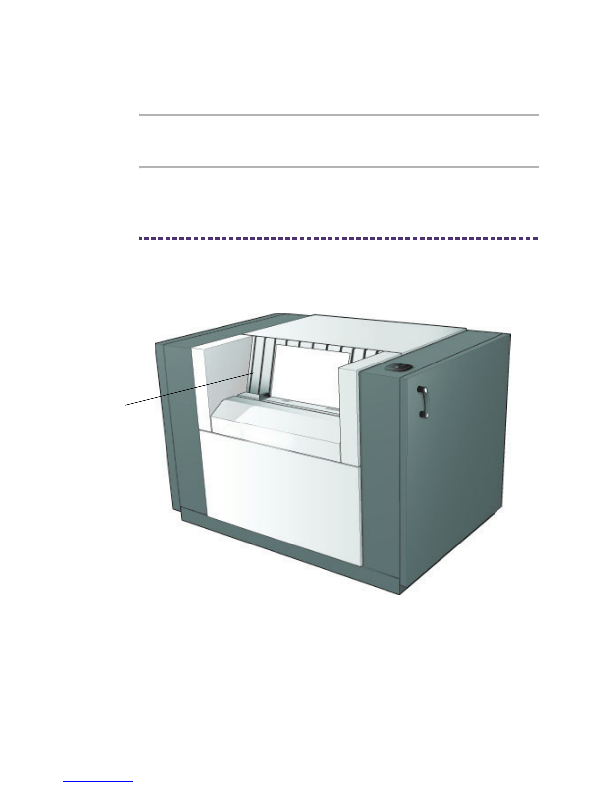
A typical Entry Level Manual platesetter is illustrated in Figure 1.1 on
page 1-2.
Figure 1.1 Entry level: manual
This module comprises the following equipment and modules:
Engine with I/O load platen.
Processor (semi-automatic only).
PAT Air Filter.
INPUT/OUTPUT
LOAD PLATEN

ALINTE4PAGE INSTALLATION GUIDE 1-3
Vacuum pump (external manufacturer supply).
RIP/PCI PC (supplied separately by the customer).
RIP application software with the options of:
Celebrant
Gateway
Rampage.
PCI (Dashboard) application - see Installation Notes with PCI
software.
1.1.2 Alinte4page Manual
A typical alinte4page manual platesetter system is illustrated in
Figure 1.2 on page 1-3.
Figure 1.2 alinte4page: manual
It comprises the following equipment and modules:
Engine with input platen.
PAT Air Filter (external manufacturer supply).
ENGINE
INPUT PLAT
EN

1-4 INTRODUCING THE ALINTE4PAGE
Vacuum pump.
RIP/PCI PC (supplied separately by the customer).
RIP application software with the options of:
Celebrant.
Gateway.
Rampage.
PCI (Dashboard) application - see Installation Notes with PCI
software.
1.1.3 Alinte4page Semi-Automatic
A typical alinte4page semi-automatic system is illustrated in
Figure 1.3 on page 1-4.
Figure 1.3 Alinte4page: semi-automatic
It comprises the following equipment and modules:
Engine with input platen.
INPUT PLATEN
ENGINE PROCESSOR

ALINTE4PAGE INSTALLATION GUIDE 1-5
PAT Air Filter (external manufacturer supply).
Vacuum pump.
Processor (external manufacturer supply).
Stacker (external manufacturer supply).
RIP/PCI PC server (supplied separately by the customer).
RIP application software with options of:
Celebrant
Gateway
Rampage.
PCI (Dashboard) application - see Installation Notes with PCI
software CD.
1.1.4 Alinte4page Single-Cassette (SAL)
A typical single-cassette alinte4page platesetter
without
a Manual
Loading Slot (MLS) is illustrated in Figure 1.4 on page 1-6. An
alinte4page
with
MLS is shown in Figure 1.5 on page 1-7.

1-6 INTRODUCING THE ALINTE4PAGE
Figure 1.4 Alinte4page: single-cassette (without MLS)
A single-cassette comprises the following equipment and modules:
Engine.
Autoloader with MLS option.
Trolley with cassette (one trolley supplied as standard with the
option ofup to five).
PAT Air Filter (external manufacturer supply).
Vacuum pump.
Processor (external manufacturer supply).
Stacker (external manufacturer supply).
RIP/PCI PC server (supplied separately by the customer)
ENGINE
AUTOLOADER
TROLLEY/ CASSETTE
PROCESSOR

ALINTE4PAGE INSTALLATION GUIDE 1-7
.
Figure 1.5 Alinte4page: single-cassette (with MLS)
RIP application software with options of:
Celebrant
Gateway
Rampage.
PCI application (see Installation Notes with PCI software CD).
1.1.5 Alinte4page Multi-Cassette (MAL)
Autoloader
A typical multi-cassette autoloader alinte4page platesetter with an
autofeeder module is illustrated in Figure 1.6 on page 1-8.
MANUAL LOAD SLOT

1-8 INTRODUCING THE ALINTE4PAGE
Figure 1.6 Alinte4page: multi-cassette (MAL)
A multi comprises the following equipment and modules:
Engine.
Autoloader.
Autofeeder.
Trolley and cassette (one trolley and two cassettes is supplied as
standard with the option of up to seven cassettes). The standard
trolley has a fixed platen. An optional tilt trolley has an adustable
platen to allow passage through narrow doorways.
PAT Air Filter (external manufacturer supply).
Vacuum pump.
Processor (external manufacturer supply).
Stacker (external manufacturer supply).
RIP/PCI PC server (supplied separately by the customer).
AUTOLOADERAUTOLOADER
AUTOLOADERAUTOFEEDER
Table of contents


