FIAMA F1X5 RS Guide

Display F1X5_RS
Data: 13/01/16 file: F1X5_RS_ing.doc Pag 1/12
USER’S MANUAL AND MAINTENANCE
MICROPROCESSOR DISPLAY F1X5_RS
WITH MODBUS RTU SERIAL OUTPUT RS232, RS485

Display F1X5_RS
Data: 13/01/16 file: F1X5_RS_ing.doc Pag 2/12
Manual purpose
This manual has been designed by the Manufacturer to provide the necessary information regarding the
instrument to those who are authorized to carry out safely its installation, maintenance, dismantling and disposal.
All the necessary information for the buyers and planners can be found in the “Sales catalogue”.
Besides than adopting good technical construction methods, the information should be read carefull yand strictly
applied.Inobservance of this information could cause risks for the health and safety of people and economical
damage. This infor-mation, provided by the Manufacturer in the original language(Italian) is also available in other
languages to satisfy legislative and/or commercial needs.
This manual must be kept in a good condition by a responsible person in an ideal place so that it is always
available for consultation. In case of loss or deteriorioraation of the manual, a replacement should be requested
directly from the manu-facturer quoting the manual’s code.
This manual reflects the state of skill of the instrument at the time of input on the market: however the
manufacturer reserves the right to make changes , add or improve the manual without giving any reason to hold
the present manual inade-quate.
Identification of the equipment
The identification plate represented is applied to the instrument. To find the
identification code of the instrument, consult the sales catalogue.
Environmental conditions
Temperature setting: min. 0°C, max. + 50°C.
It is forbidden to use the instrument other than its specific use and in potentially explosive conditions or where anti-
explosive elements are used.
Storage
Here below are some references to be followed for the storage of the instrument
Avoid environments with excessive humidity and those exposed to bad weather (avoid open areas). Avoid putting
the instrument directly on the ground. Store the instrument in its original packing.
Conformity declaration and EC marking
The instrument answers to the following Communitarian Directives:
2014/30/EU Electromagnetic compatibility, 2014/35/EU Low voltage, 2011/65/EU RoHS.
Maintenance
Reparations should be done only and exclusively at the FIAMA technical assistance centre.
Turn off the power before touching the internal parts. Clean the external plastic parts using a soft, damp cloth with
ethylic alcohol or water.
Do not use hydrocarbon solvents (petrols, diluants): using these products could affect the proper mechanical
functioning of the instrument.
Calibrations and tests
It is advisable to calibrate the instrument periodically, once every working year. To do the calibration , follow the
calibration procedure indicated in the present manual .
For any kind of technical assistance request, contact the sales department of the Manufacturer directly indicating
the information given on the identification plate, the number of hours used and the type of defect.
Manufacturer’s responsibility
The manufacturer declines any responsibility in case of :
• Using the instrument contrary to the national safety and accident-prevention laws.
• Wrong installation, inobservnace or wrong procedures of the instructions provided in the present manual.
• Defective electrical power supply.
• Modifications or tamperings.
• Operations carried out by untrained or unqualified personnel.
The safety of the instrument also depends on the strict observance of the procedures indicated in the manual:
always operate the instument in its functioning capacity and carry out a careful routine maintenance.
• All phases of inspection and maintenance should be done by qualified personnel.
• The configurations provided in the manual are the only ones permitted.
• Do not try to use them anyway contrary to the indications provided.
• The instructions in this manual do not substitute but accomplish the obligations of the current legislation
regarding the safety laws.

Display F1X5_RS
Data: 13/01/16 file: F1X5_RS_ing.doc Pag 3/12
Description
The F1X5_ is a mono-bidirectional microprocessor multiple keyboard counter, that processes signals
supplied by incremental transducers (encoders, optical lines, etc…) on a 5 digit display (reading scale –99999
+99999). The programming of this microprocessor is carried out by means of four keys on the frontal panel,
after introducing a password. The microprocessor allows the operator to set the input pulse correction
factors, and to multiply these factors by a 6 digit coefficient. The device has a serial output connection RS485
(or RS232) with MODBUS RTU protocol to dialogue with remote units. This instrument can keep its data in
memory also when the machine is switched off thanks to a not volatile Eeprom memory. The Reset-Enter
digit is employed to input a Preset quote too. By means of the input located on the terminal-board you can
switch on the Reset or Preset functions. This instrument is set inside a 48 x 96 panel case according to DIN
43700.
Front view
RESET
ENTER
PGM
set1 set2
Rear view
12345678
123456
Terminal Block
Power Supply/Transducer
Terminal Block:
Serial Output
M2
M1
78
910
Installation
Before installing the instrument, read the following warnings:
a) Connect the instrument strictly following the instructions of the manual.
b) Carry out the connections using the correct wires within the limits of the tension and power supply as indicated
in
the technical data.
c) The instrument does not have an ON/OFF switch, hence it comes on when connected to the power supply. For
safety reasons, the equipment connected permanently to the power supply requires a bi-phasal selector switch
which should be within easy reach of the operator.
d) If the instrument is connected to any apparatus not isolated electrically, carry out an earth connection to avoid it
being connected directly through the structure of the machine.
d) It is the responsibility of the user to check, before using, the correct settings of the parameters of the instrument
to avoid damage to persons or things.
e) The instrument cannot function in a dangerous environment (inflammable or explosive). It can be connected to
elements that operate in the same atmosphere only through appropriate interfaces, according to the current safety
regulations.
g) Avoid dust, humidity, corrosive gases, heat sources.
h) Do not block air vents, the work temperature should be maintained between 0 ÷ 50°C.

Display F1X5_RS
Data: 13/01/16 file: F1X5_RS_ing.doc Pag 4/12
Power supply
a) Before connecting the instrument, check that the the power supply tension is within the permitted limits and that
it corresponds to the one indicated on the tag.
b) Carry out the electrical connections with the instrument disconnected.
c) For the power line to instruments and sensors, a power supply line separate from that of the power is required :
it is necessary to use an isolating transformer.
d) The power line should forsee a device that separates the set fuses of the instruments and should not be used to
regulate, meters, etc.
e) If the network tension is very disordered (eg. from the change-over of the power units, motors, inverters,
welders,
etc.), use the appropriate filters of the network.
f) If an earth connection is needed, ensure that the plant has a good earth system: tension between neutral and
earth <1V and the resistance <6 Ohm.
Connections entries and exits
a) Physically separate the entry wires from those of the power supply, the exits and the power connections; use
twined and shielded wires with the display connected to the earth only at one point.
b) Connect the exits of adjustments, alarms (meters, electrovalves, motors, ventilators, etc.) assembling units RC
(resistance and condenser in series) parallel to the charged inductives that work alternatively.
Assembly of the instrument
To carry out the correct installation of the instrument, it is necessary to follow the shown procedure:
1. Insert the instrument in the opening provided.
2. Screw the screw on the fixing block.
3. Hook the block to the instrument through the joints.
4. Block the instrument by screwing the screws of the two blocks.
5. Then carry out the electrical connections.
To assemble several instruments placed side by side, it is necessary to follow the interaxes as shown in the
design.
The articles A and B can be read under space dimensions found in the present manual.

Display F1X5_RS
Data: 13/01/16 file: F1X5_RS_ing.doc Pag 5/12
PROGRAMMING
In the scheme below you can find the programming digits associated to their peculiar functions:
PGM To start the programming
To increase the number, which is being modified.
To select the constant to modify
To proceed from one numeral to the following one.
To leave the constant programming sections
RESET/ENTER To confirm the data you have just inserted
Press PGM To start the programming section: the number “000” , whose first numeral on the
right flashes, is displayed. At this point you are requested to insert the number 273
in the following way:
press to increase the flashing number
Press to select the flashing number
After introducing 273 pls. confirm by means of RESET/ENTER . For some seconds you will read the word
“Set1” followed by its own value.
N.B.: If you input a false password, the instrument will immediately leave the programming phase.
Press RESET/ENTER and modify the constant value by means of the digits
Press RESET/ENTER again to confirm your choice
Press to start working with other constants or
Press to leave the programming section
The constants, which have to be programmed, and can be run over by the digit are the following ones:
Threshold for relay 1, not used in version without relay
Threshold for relay 1, not used in version without relay
The display shows a value after 1 encoder revolution
Impulse number after one encoder revolution
Decimal numbers
Preset quote
Zero setting
Input selection (encoder or proximity sensor)
Debounce of the count inputs
Start of the output relay , not used in version without relay
Thresholds for the relays, not used in version without relay
# % Baud rate serial port comunication
%%. Address device
Constants
Threshold for Relay 1
Not used in version without relay.
Threshold for Relay 2
Not used in version without relay.

Display F1X5_RS
Data: 13/01/16 file: F1X5_RS_ing.doc Pag 6/12
Value which Corresponds to 1 Encoder Revolution
This instrument can correct the impulses, and multiply them by a coefficient, which corresponds to the ratio
between constant and . If you programme these two constants correctly the display will
visualize the value you need with a certain number of impulses (they are reckoned in the inputs). The
programmed value of this parameter represents the value visualized on the display.
The interval value of this count is programmable between 0 ÷999999.
Number of Impulses for every Encoder Revolution
The value, which should programmed in this section, represents the number of impulses for every encoder
revolution, this is to say the division factor of input impulses.
The interval of the allowed values is 0 ÷999999.
Example 1:
If you have a 100 impulse/rev. Encoder, and for every revolution you need to visualize 123,4567 pls. follow
the next description: VISUAL=1234 and IMPULS=100 . If you need to input a decimal number in the second
position too, pls. insert N.DEC=1.
N.B:In order to reduce the approximation error we suggest you to multiply VISUAL and IMPULS by 10 or 100 or
1000 . With reference to the above mentioned values you will get :123.4567 x 100 =123456 and
IMPULS=10000.
The value will be composed by 6 numerals (instead of 4) for every visualization.
Example 2:
If you have a proximity sensor, and after 10 impulses you need to see the value 7, pls. programme in the
following way: VISUAL=7 and IMPULS=10.
Decimal Numbers
This constant shows the decimal point position : programme 0 if you have not any decimal number, 1 for 1
decimal number, ecc… Accepted values: from 0 to 4.
Preset
This instrument allows you to programme a value which will be shown after pressing RESET/ENTER or after
activating the Reset input in the key-board according to the scheme M.Azz. “Zero setting” .
The allowed values are included between –999999 and 999999.
Zero setting
By means of the zero-setting programming you can select the function of the instrument after choosing the
RESET/ENTER digit or after starting the RESET in the terminal board.
The Reset function zeros the visualized quote on the display, while the Preset shows the value, which has been
programmed in the constant before hand.
According to the following scheme, please choose your preferred type of zero setting :
PRESET Input RESET/ENTER Digit
0 Reset Disabled Digit
1 Preset Disabled Digit
2 Reset Reset
3 Reset Preset
4 Preset Reset
5 Preset Preset
6 Disabled Input Reset
7 Disabled Input Preset
8 Disabled Input Disabled Digit
9 Disabled Input Delayed Reset (press for about 3 sec)

Display F1X5_RS
Data: 13/01/16 file: F1X5_RS_ing.doc Pag 7/12
Inputs
By means of this constant you can programme the input types, and count according to the following scheme:
Input
0 Bidirectional count from an encoder with 2 quadrate channels
1 Monodirectional count with input coming from a sensor or a mechanical
contact :
A = count impulses (from open to closed)
B = count direction: when B is open, the count increases,
when B is closed the count decreases *
2 Monodirectional count with input coming from a sensor or a mechanical
contact:
A = Count impulses (from open to closed)
B = count direction: when B is open the count increases,
when B is closed the count decreases
3 Bidirectional count with inputs coming from sensors or mechanical
contacts :
A = Increasing count impulses from open to closed phase
B = Decreasing count impulses from open to closed phase
4 Bidirectional count with inputs coming from sensors or mechanical
contacts :
A = Increasing count impulses from closed to open phase
B = Decreasing count impulses from closed to open phase
* B has to be connected to GND if the sensor is NPN; to +12V if the sensor is PNP ( see connection scheme )
Debounce Filter for Count Inputs
If you use an input coming from a mechanical contact in order to avoid debounce impulses you have to
programme this constant “1”. In this case you can start a filtre of 10Hz in the count inputs, which avoids
interferences in the opening or in the mechanical connection of the instrument.
This constant can have only a 0 value (except for the filtre), and 1 (working filtre).[ It does not matter if you
chose a bidirectional encoder with quadrature channels in the opening phase! ( INPUT CONSTANT = 0)].
Output Relays
Not used in version without relay.
Relay Thresholds Outside the Password Section
Not used in version without relay.
# % Baud rate serial port comunication
# % Baude rate
0 600
1 1200
2 2400
3 4800
4 9600
5 19200
%%. Address device
This is the identification address of the unit, it must be unique for every device connected to the bus network,
admitted value from 1 to 247.

Display F1X5_RS
Data: 13/01/16 file: F1X5_RS_ing.doc Pag 8/12
Transducers connection scheme Terminal Block M1
GND
A
B
+12V
/A
/B
GND
A
B
+Vcc
Bi-directional encoder connection
open collector or push-pull output
NPN
A
B
+12V
/A
/B
GND
GND
A
B
+Vcc
Bi-directional encoder connection
Open collector or push-pull
PNP
Mono-directional or proximity transducer connection
Open collector or push-pull
NPN
Mono-directional or proximity encoder connection
Open collector or push-pull
PNP
GND
B
A
+12V
/A
/B
GND
A
B
+12V
/B
/A
GND
A
+Vcc
GND
A
+Vcc
NB
With jumper
Decreasing count
B-GND
Without jumper
Increasing
B-GND
count
NB
With jumper
Decreasing
/B +12V
count
Without any jumper
increasing
/B +12V
Count
5
3
6
4
2
1
5
3
6
2
1
4
6
5
3
1
4
2
5
6
3
1
4
2
Overall dimensions

Display F1X5_RS
Data: 13/01/16 file: F1X5_RS_ing.doc Pag 9/12
Connections scheme
1
2
3
4
5
6
7
8
9
10
GND
A
/A
B
/B
+12V
R/P
230Vac
115Vac 0
24Vac 0
15-30Vdc GND
+Vcc
/B
GND
A
/A
B
M1
Bi-directional connection to the encoder
Line-driver differential output
Micro RESET/PRESET
(max 60 mA)
F1X50
F1X52
F1X53
0F1X51
SERIAL OUTPUT CONNECTION
M2
1
2
3
4
5
6
GND SERIAL OUT
7
8
RX (RS232) / RS+ (RS485)
TX (RS232) / RS- (RS485)
NB: only one serial output port (RS232 or RS485) is active.
Please refer to F1X5 model.

Display F1X5_RS
Data: 13/01/16 file: F1X5_RS_ing.doc Pag 10/12
MODBUS PROTOCOL OF SERIAL PORT CONNECTION
The device has a serial output connection RS485 (or RS232) with MODBUS RTU protocol to dialogue with
remote units, 8bit data; 1 bit di stop; no parity. The Protocol is based on a QUERY/RESPONSE structure: the
slave devices reply to the queries with a message that contains the identifying address and the requested
data. It is possible to read and write the parameters of the F1X5_RS, called configuration registers.
The MODBUS protocol ensures the validity of the exchanged data through the line by a “Cyclic Redundance
Check” error check; two CRC bytes of are added to the messages. The algorithm to make two bytes of CRC
in Pascal language and C is provided.
Routine CRC in linguaggio PASCAL Routine CRC in linguaggio C
Function CRC16(messaggio:string; var Hi: byte; var Lo: byte):Word;
const auchCRCHi: array[0..255] of byte = (
$00, $C1, $81, $40, $01, $C0, $80, $41, $01, $C0,
$80, $41, $00, $C1, $81, $40, $01, $C0, $80, $41,
$00, $C1, $81, $40, $00, $C1, $81, $40, $01, $C0,
$80, $41, $01, $C0, $80, $41, $00, $C1, $81, $40,
$00, $C1, $81, $40, $01, $C0, $80, $41, $00, $C1,
$81, $40, $01, $C0, $80, $41, $01, $C0, $80, $41,
$00, $C1, $81, $40, $01, $C0, $80, $41, $00, $C1,
$81, $40, $00, $C1, $81, $40, $01, $C0, $80, $41,
$00, $C1, $81, $40, $01, $C0, $80, $41, $01, $C0,
$80, $41, $00, $C1, $81, $40, $00, $C1, $81, $40,
$01, $C0, $80, $41, $01, $C0, $80, $41, $00, $C1,
$81, $40, $01, $C0, $80, $41, $00, $C1, $81, $40,
$00, $C1, $81, $40, $01, $C0, $80, $41, $01, $C0,
$80, $41, $00, $C1, $81, $40, $00, $C1, $81, $40,
$01, $C0, $80, $41, $00, $C1, $81, $40, $01, $C0,
$80, $41, $01, $C0, $80, $41, $00, $C1, $81, $40,
$00, $C1, $81, $40, $01, $C0, $80, $41, $01, $C0,
$80, $41, $00, $C1, $81, $40, $01, $C0, $80, $41,
$00, $C1, $81, $40, $00, $C1, $81, $40, $01, $C0,
$80, $41, $00, $C1, $81, $40, $01, $C0, $80, $41,
$01, $C0, $80, $41, $00, $C1, $81, $40, $01, $C0,
$80, $41, $00, $C1, $81, $40, $00, $C1, $81, $40,
$01, $C0, $80, $41, $01, $C0, $80, $41, $00, $C1,
$81, $40, $00, $C1, $81, $40, $01, $C0, $80, $41,
$00, $C1, $81, $40, $01, $C0, $80, $41, $01, $C0,
$80, $41, $00, $C1, $81, $40) ;
const auchCRCLo: array [0..255] of byte = (
$00, $C0, $C1, $01, $C3, $03, $02, $C2, $C6, $06,
$07, $C7, $05, $C5, $C4, $04, $CC, $0C, $0D, $CD,
$0F, $CF, $CE, $0E, $0A, $CA, $CB, $0B, $C9, $09,
$08, $C8, $D8, $18, $19, $D9, $1B, $DB, $DA, $1A,
$1E, $DE, $DF, $1F, $DD, $1D, $1C, $DC, $14, $D4,
$D5, $15, $D7, $17, $16, $D6, $D2, $12, $13, $D3,
$11, $D1, $D0, $10, $F0, $30, $31, $F1, $33, $F3,
$F2, $32, $36, $F6, $F7, $37, $F5, $35, $34, $F4,
$3C, $FC, $FD, $3D, $FF, $3F, $3E, $FE, $FA, $3A,
$3B, $FB, $39, $F9, $F8, $38, $28, $E8, $E9, $29,
$EB, $2B, $2A, $EA, $EE, $2E, $2F, $EF, $2D, $ED,
$EC, $2C, $E4, $24, $25, $E5, $27, $E7, $E6, $26,
$22, $E2, $E3, $23, $E1, $21, $20, $E0, $A0, $60,
$61, $A1, $63, $A3, $A2, $62, $66, $A6, $A7, $67,
$A5, $65, $64, $A4, $6C, $AC, $AD, $6D, $AF, $6F,
$6E, $AE, $AA, $6A, $6B, $AB, $69, $A9, $A8, $68,
$78, $B8, $B9, $79, $BB, $7B, $7A, $BA, $BE, $7E,
$7F, $BF, $7D, $BD, $BC, $7C, $B4, $74, $75, $B5,
$77, $B7, $B6, $76, $72, $B2, $B3, $73, $B1, $71,
$70, $B0, $50, $90, $91, $51, $93, $53, $52, $92,
$96, $56, $57, $97, $55, $95, $94, $54, $9C, $5C,
$5D, $9D, $5F, $9F, $9E, $5E, $5A, $9A, $9B, $5B,
$99, $59, $58, $98, $88, $48, $49, $89, $4B, $8B,
$8A, $4A, $4E, $8E, $8F, $4F, $8D, $4D, $4C, $8C,
$44, $84, $85, $45, $87, $47, $46, $86, $82, $42,
$43, $83, $41, $81, $80, $40) ;
var i, index: integer;
begin
Hi := $FF ;
Lo := $FF ;
for i:=1 to length(messaggio) do
begin
index := Hi xor ORD(messaggio[i]);
Hi := Lo xor auchCRCHi[index];
Lo := auchCRCLo[index];
end;
static unsigned char auchCRCHi[] = {
0x00, 0xC1, 0x81, 0x40, 0x01, 0xC0, 0x80, 0x41, 0x01, 0xC0,
0x80, 0x41, 0x00, 0xC1, 0x81, 0x40, 0x01, 0xC0, 0x80, 0x41,
0x00, 0xC1, 0x81, 0x40, 0x00, 0xC1, 0x81, 0x40, 0x01, 0xC0,
0x80, 0x41, 0x01, 0xC0, 0x80, 0x41, 0x00, 0xC1, 0x81, 0x40,
0x00, 0xC1, 0x81, 0x40, 0x01, 0xC0, 0x80, 0x41, 0x00, 0xC1,
0x81, 0x40, 0x01, 0xC0, 0x80, 0x41, 0x01, 0xC0, 0x80, 0x41,
0x00, 0xC1, 0x81, 0x40, 0x01, 0xC0, 0x80, 0x41, 0x00, 0xC1,
0x81, 0x40, 0x00, 0xC1, 0x81, 0x40, 0x01, 0xC0, 0x80, 0x41,
0x00, 0xC1, 0x81, 0x40, 0x01, 0xC0, 0x80, 0x41, 0x01, 0xC0,
0x80, 0x41, 0x00, 0xC1, 0x81, 0x40, 0x00, 0xC1, 0x81, 0x40,
0x01, 0xC0, 0x80, 0x41, 0x01, 0xC0, 0x80, 0x41, 0x00, 0xC1,
0x81, 0x40, 0x01, 0xC0, 0x80, 0x41, 0x00, 0xC1, 0x81, 0x40,
0x00, 0xC1, 0x81, 0x40, 0x01, 0xC0, 0x80, 0x41, 0x01, 0xC0,
0x80, 0x41, 0x00, 0xC1, 0x81, 0x40, 0x00, 0xC1, 0x81, 0x40,
0x01, 0xC0, 0x80, 0x41, 0x00, 0xC1, 0x81, 0x40, 0x01, 0xC0,
0x80, 0x41, 0x01, 0xC0, 0x80, 0x41, 0x00, 0xC1, 0x81, 0x40,
0x00, 0xC1, 0x81, 0x40, 0x01, 0xC0, 0x80, 0x41, 0x01, 0xC0,
0x80, 0x41, 0x00, 0xC1, 0x81, 0x40, 0x01, 0xC0, 0x80, 0x41,
0x00, 0xC1, 0x81, 0x40, 0x00, 0xC1, 0x81, 0x40, 0x01, 0xC0,
0x80, 0x41, 0x00, 0xC1, 0x81, 0x40, 0x01, 0xC0, 0x80, 0x41,
0x01, 0xC0, 0x80, 0x41, 0x00, 0xC1, 0x81, 0x40, 0x01, 0xC0,
0x80, 0x41, 0x00, 0xC1, 0x81, 0x40, 0x00, 0xC1, 0x81, 0x40,
0x01, 0xC0, 0x80, 0x41, 0x01, 0xC0, 0x80, 0x41, 0x00, 0xC1,
0x81, 0x40, 0x00, 0xC1, 0x81, 0x40, 0x01, 0xC0, 0x80, 0x41,
0x00, 0xC1, 0x81, 0x40, 0x01, 0xC0, 0x80, 0x41, 0x01, 0xC0,
0x80, 0x41, 0x00, 0xC1, 0x81, 0x40
} ;
static char auchCRCLo[] = {
0x00, 0xC0, 0xC1, 0x01, 0xC3, 0x03, 0x02, 0xC2, 0xC6, 0x06,
0x07, 0xC7, 0x05, 0xC5, 0xC4, 0x04, 0xCC, 0x0C, 0x0D, 0xCD,
0x0F, 0xCF, 0xCE, 0x0E, 0x0A, 0xCA, 0xCB, 0x0B, 0xC9, 0x09,
0x08, 0xC8, 0xD8, 0x18, 0x19, 0xD9, 0x1B, 0xDB, 0xDA, 0x1A,
0x1E, 0xDE, 0xDF, 0x1F, 0xDD, 0x1D, 0x1C, 0xDC, 0x14, 0xD4,
0xD5, 0x15, 0xD7, 0x17, 0x16, 0xD6, 0xD2, 0x12, 0x13, 0xD3,
0x11, 0xD1, 0xD0, 0x10, 0xF0, 0x30, 0x31, 0xF1, 0x33, 0xF3,
0xF2, 0x32, 0x36, 0xF6, 0xF7, 0x37, 0xF5, 0x35, 0x34, 0xF4,
0x3C, 0xFC, 0xFD, 0x3D, 0xFF, 0x3F, 0x3E, 0xFE, 0xFA, 0x3A,
0x3B, 0xFB, 0x39, 0xF9, 0xF8, 0x38, 0x28, 0xE8, 0xE9, 0x29,
0xEB, 0x2B, 0x2A, 0xEA, 0xEE, 0x2E, 0x2F, 0xEF, 0x2D, 0xED,
0xEC, 0x2C, 0xE4, 0x24, 0x25, 0xE5, 0x27, 0xE7, 0xE6, 0x26,
0x22, 0xE2, 0xE3, 0x23, 0xE1, 0x21, 0x20, 0xE0, 0xA0, 0x60,
0x61, 0xA1, 0x63, 0xA3, 0xA2, 0x62, 0x66, 0xA6, 0xA7, 0x67,
0xA5, 0x65, 0x64, 0xA4, 0x6C, 0xAC, 0xAD, 0x6D, 0xAF, 0x6F,
0x6E, 0xAE, 0xAA, 0x6A, 0x6B, 0xAB, 0x69, 0xA9, 0xA8, 0x68,
0x78, 0xB8, 0xB9, 0x79, 0xBB, 0x7B, 0x7A, 0xBA, 0xBE, 0x7E,
0x7F, 0xBF, 0x7D, 0xBD, 0xBC, 0x7C, 0xB4, 0x74, 0x75, 0xB5,
0x77, 0xB7, 0xB6, 0x76, 0x72, 0xB2, 0xB3, 0x73, 0xB1, 0x71,
0x70, 0xB0, 0x50, 0x90, 0x91, 0x51, 0x93, 0x53, 0x52, 0x92,
0x96, 0x56, 0x57, 0x97, 0x55, 0x95, 0x94, 0x54, 0x9C, 0x5C,
0x5D, 0x9D, 0x5F, 0x9F, 0x9E, 0x5E, 0x5A, 0x9A, 0x9B, 0x5B,
0x99, 0x59, 0x58, 0x98, 0x88, 0x48, 0x49, 0x89, 0x4B, 0x8B,
0x8A, 0x4A, 0x4E, 0x8E, 0x8F, 0x4F, 0x8D, 0x4D, 0x4C, 0x8C,
0x44, 0x84, 0x85, 0x45, 0x87, 0x47, 0x46, 0x86, 0x82, 0x42,
0x43, 0x83, 0x41, 0x81, 0x80, 0x40
} ;
unsigned short CRC16(unsigned short usDataLen)
{
uchCRCHi = 0xFF ;
uchCRCLo = 0xFF ;
while (usDataLen--)
{
uIndex = uchCRCHi ^ *puchMsg++ ;
uchCRCHi = uchCRCLo ^ auchCRCHi[uIndex] ;
uchCRCLo = auchCRCLo[uIndex] ;
}
return (uchCRCHi << 8 | uchCRCLo) ;

Display F1X5_RS
Data: 13/01/16 file: F1X5_RS_ing.doc Pag 11/12
Further Information on the making of the two CRC bytes are available on the site www.modicon.com.
The F1X5 MODBUS commands are:
0x03: multiple reading of registers
0x10: writing of several registers.
0x03 READING OF REGISTERS
To read the registers of the instrument, the master must send a query composed as follows (every element is
a byte):
ADDRESS | 0x03 | START_REG_HI | START_REG_LO | N_REG_HI | N_REG_LO | CRC_HI | CRC_LO
- START_REG_HI | START_REG_LO is the address at the starting 16 bit for the reading
- N_REG_HI | N_REG_LO is the number (16 bit) of the registers to be read
The instrument replies with the following message:
ADDRESS | 0x03 | NBYTE | DATA_1_HI | DATA_1_LO | DATA_2_HI | DATA_2_LO | …
| CRC_HI | CRC_LO
- DATA_1_HI | DATA_1_LO | DATA_2_HI | DATA_2_LO | … is the sequence of the data
read..
NBYTE is the number of the given bytes that follow
0x10 WRITING OF REGISTERS
To write the registers of the instrument, the master must send a query composed as follows (every element is
a byte):
ADDRESS | 0x10 | START_REG_HI | START_REG_LO | N_REG_HI | N_REG_LO | NBYTE | DATA_1_HI |
DATA_1_LO | DATA_2_HI | DATA_2_LO |…… | CRC_HI | CRC_LO
NBYTE is the number of the given bytes that follow.
The instrument replies with the following message:
ADDRESS | 0x10 | START_REG_HI | START_REG_LO | N_REG_HI | N_REG_LO | CRC_HI | CRC_LO
ATTENTION!!: to make operative the new value introduced you must send the “reload parameter”
command writing in the Operation Register (*) (address 0x15) the value 0x01.
Exceptions management:
In case the slave recognizes an error in the query received and addressed to it, it replies with an exceptional
message composed as following:
ADDRESS | FUNCTION_CODE + 0x80 | EXCEPT. CODE | CRC_HI | CRC_LO
The Exception Code can be one of the following:
01 Æ
ÆÆ
ÆIllegal Function: The function code received in the query is not valid.
02 Æ
ÆÆ
ÆIllegal Data Address: The address received in the query is not valid.
03 Æ
ÆÆ
ÆIllegal Data Value: A value contained in the query is not valid.

Display F1X5_RS
Data: 13/01/16 file: F1X5_RS_ing.doc Pag 12/12
REGISTER TABLE
Register Address Hex N° of byte register
Threshold for relay 1, HIGH (#) (not used w/o relay) 0x00 2 byte (HIGH byte don’t care)
Threshold for relay 1 LOW (#) (not used w/o relay 0x01 2 byte
Threshold for relay 2 HIGH (#) (not used w/o relay 0x02 2 byte (HIGH byte don’t care)
Threshold for relay 2 LOW (#) (not used w/o relay 0x03 2 byte
Visual HIGH 0x04 2 byte (HIGH byte don’t care)
Visual LOW 0x05 2 byte
Impuls HIGH 0x06 2 byte (HIGH byte don’t care)
Impuls LOW 0x07 2 byte
Decimal N° 0x08 2 byte (HIGH byte don’t care)
Preset HIGH 0x09 2 byte (HIGH byte don’t care)
Preset LOW 0x0a 2 byte
Zero setting 0x0b 2 byte (HIGH byte don’t care)
Input selection 0x0c 2 byte (HIGH byte don’t care)
Filter debounce input 0x0d 2 byte (HIGH byte don’t care)
Relays mode (not used) 0x0e 2 byte (HIGH byte don’t care)
Time activation relays (not used) 0x0f 2 byte (HIGH byte don’t care)
Thresholds relays under password (not used w/o relay) 0x10 2 byte (HIGH byte don’t care)
Absolute counting value HIGH (#) 0x11 2
Absolute counting value LOW (#) 0x12 2
Relative counting value HIGH (#) 0x13 2
Relative counting value LOW (#) 0x14 2
Operation Register (*) 0x15 2 byte (HIGH byte don’t care)
(#) this parameter is expressed in encoder count number, then is not multiplied by VISUAL/IMPULS correction
factor. The value read from serial port is equal to the display value only if VISUAL/IMPULS =4.
Technical Features
Power supply 115Vac, 230Vac, 24Vac, 15÷30Vdc ±10%
Line frequency 50/60 Hz
Power absorbtion 3 VA
Display –99999; 999999
Inputs type Optoisolated
Encoder power supply 12Vdc (max 60mA)
Count input Open collector NPN/PNP
Push-pull
Differential Line driver
Mechanical contact
Input maximum frequency 10 KHz
Count possibility Bi-directional
Monodirectional (counting up)
Monodirectional (counting down)
Serial port connection RS232 or RS485 MODBUS RTU protocol
Working temperature 0-50°C
Relative humidity 10-90%
Size (with terminal box) 48x96x100 mm
Drilling template 45x92 mm
Front case protection IP54
Electromagnetic compatibility 2014/30/EU
Low voltage 2014/35/EU
RoHS 2011/65/EU
Manufacturer
All communications to the manufacturer should be addressed to:
FIAMA s.r.l., Via G. Di Vittorio, 5/A - 43016 San Pancrazio (Parma) - Italy
FIAMA srl is not responsible for any damage to persons or things caused by tamperings and wrong use
and in any case that are not consistent with the features of the instrument.
Table of contents
Popular Computer Hardware manuals by other brands

SeaLevel
SeaLevel SEAI/OUSBSERIAL user manual

National Instruments
National Instruments PCI-6110E/6111E user manual

AXIOMTEK
AXIOMTEK eBOX660-872-FL Quick installation guide
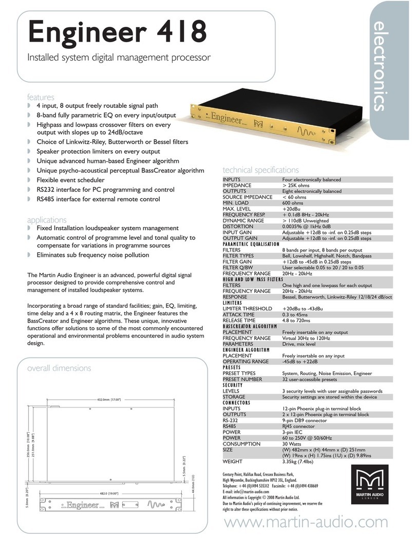
Martin Audio
Martin Audio Installed System Digital Management Processor Engineer... Technical specifications
ADLINK Technology
ADLINK Technology cPCI-6636 Series user manual

Z3 Technology
Z3 Technology Z3-DM8107-SDI-RPS User instructions
