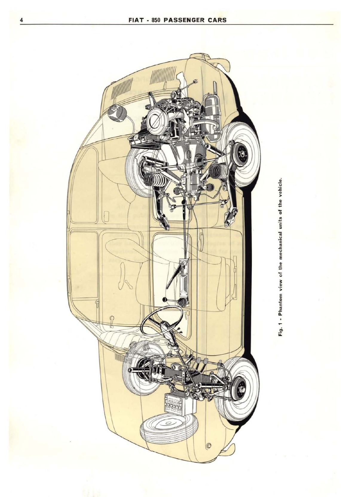
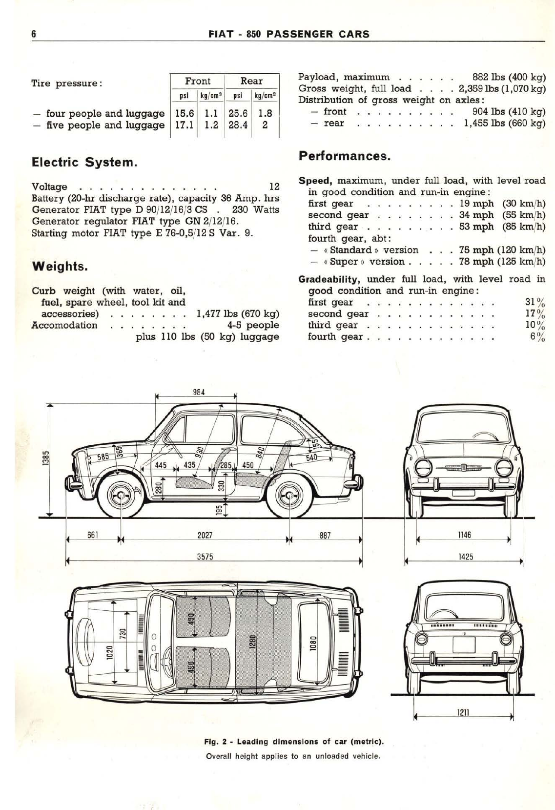
Fiat 850 Sedan 1968 Install guide


SECTION
INDEX
GENERAL
ENGINE
Section
Page
1
3
2
SEDAN
COUPE
ROADSTER·
FAMILY
IDROCONVERT
9
'85
AIR
CONDITIONING
WINDSHIELD
WASHER
TIGHTENING
REFERENCE
BRAKES
WHEELS
AND
TIRES
STEERING
17
============~
157
I,Q
9
LUBRICATION
~
COOLING
FUEL
SYSTEM
CLUTCH
-
TRANSMISSION
4
DIFFERENTIAL
FRONT
SUSPENSION
,~
AND
WHEELS
REAR
SUSPENSION
",
AND
WHEELS
.§
SHOCK
ABSORBERS
MANUAL
MODEL
SHOP
BODY
.
ELECTRICAL
110
~========~
195
lu
FIAT"
SERVICE
DEPARTMENT"
TURIN
MAINTENANCE
1~
TOOL
EQUIPMENT
COUPE·
ROADSTER
1~
FAMILY.IDROCONVERT

IMPORTANT
All
the
dimensions
in
metric
units
shown
in
this
publication
are
the
official
ones.
Dimensions
are
also
given
in
British
and
American
units
for
prompt
reference,
and
they
have
been
calculated
to
a
degree
of
ap-
proximation
according
to
the
need
for
accu-
racy
in
individual
measurements.

Section
1
GENERAL
INfORMATION
MAIN
SPECIFICATIONS
PERFORMANCES
CAPACITIES
UNIT
IDENTIFICATION
DATA
SPARE
PARTS
CAR
KEYS
Page
:11
7
8
8
8

4
FIAT·850
PASSENGER
CARS
•
u
~
•
>
•
=
0
"0
~
<
,
..
.
~
<
•
~
u
•
E
u~
•
=
'0
•
••
>
E
~
<
•
~
..
~
..
;;:

GENERAL:
MAIN
SPECIFICATIONS
5
GENERAL INFORMATION
Specifications,
features
and
service
procedures
outlined
in
this
publication
are
intended
to
apply
to
the
Sedan
Version.
Differing
parts,
data
and
procedures
of
Coupe,
Roadster,
Station
Wagon
and
Idroconvert
Versions,
as referred
to
the
Sedan,
are
described
in
Section
13.
Wear
limit
figures
are
given
just
for
the
serviceman's
information
and
should
not
be
taken
as
absolute
values.
MAIN
SPECIFICATIONS
Identification
Data.
Chassis
type
.
Engine
type
!•
Standard.
version
•
Super.
version
lOOG
lOOG.OOO
lOOG.OO2
3rd,
synchromeshed
4th, •
Reverse
.
Hypoid
final
drive
gear
ratio
Steering.
1.409 to I
0.963
to I
3.615
to
I
4.625 to I(8/37)
13 to I(2/26)
31'
6"
(9.60
m)
Worm-and-seetor.
Gear
ratio
..
Turning
circle
. .
Front
Suspension.
Rear
Suspension.
Independent
wheel.
Coil
springs,
control
arms,
hydraulic
shock
absor-
bers,
sway
bar.
Rear
wheel
toe-in
(full
load)
.039"
to
.118"
(I
to
3rom).
Independent
wheel.
Transversal
semi-elliptic
spring,
upper
control
arms,
hydraulic
shock
absorbers,
sway
bar.
Toe-in
(full
load).
079"
to
.157" (2 to 4rom)
Camber
(full
load):
-
angle
.
20
10'±
IS'
-
amount,
at
wheel
rim
.472"
to
.512"
(12 to 13 rom)
Caster.
. . . . . . . . . . .
gO±lo
40
42
.5,300 r
.p.m.
.5,300
r.p.m.
8.0
to I
8.8
to I
rear
4-stroke,
gasoline
4,
in-line
2.559"
(65 rom)
2.500"
(63.5 rom)
.51.44
cu.in
(843
em')
Engine.
Location .
Cycle
..
No. of
cylinders
Bore
.
Stroke
. . . . .
Piston
displacement
.
Compression
ratio:
-(I
Standard
l)
version
-(I
Super»
version.
.
Maximum
horsepower
(SAE):
- •
Standard»
version
-
4l
Super
t
version.
.
f
4l
Standard.
version
. .
at
}.
Super.
version
. . .
Maximum
horsepower
(DIN):
- •
Standard.
version
34
-•
Super.
version.
.37
I.
Standard.
version
.4,800 r
.p.m.
at •
Super.
version
. . 5,000 r
.p.m.
Taxable
horsepower
Otaly)
II
Cooling .......
permanent
circuit
mixture
Clutch.
Brakes.
Single
plate.
dry.
Diaphragm-type
pressure
spring.
Transmission·
Differential.
Drum
diameter
. . . . .
Master
cylinder
bore
. .
Bore
of
wheel
cylinders:
-
front
-rear .
7.283"
(185 rom)
3/4"
7/6"
3/4".
Rear
drive.
Gear
ratios:
1st,
synchromeshed
2nd,
t3.636 to I
2.055
to
I
Wheels
and
Tires.
Disc
wheels,
size
Tire
size
.... 4.00-12"
5.50-12"

6
FIAT·
850
PASSENGER
CARS
Tire
pressure:
four
people
and
luggage
five
people
and
luggage
Front
Rear
~
kg/em'
_"_'_1
kg/em'
15.6
1.1
25.6 1.6
17.1 1.2 28.4 2
Payload,
maximum
, . . .
..
852
lbs
(400 kg)
Gross
weight,
full
load
. , .
,2,359lbs(I,070kg)
Distribution
of
gross
weight
on
axles:
front
904lbs
(410 kg)
-
rear
..
........ 1,455
lbs
(660 kg)
Electric
System.
Performances.
Weights.
31%
17%
10%
6%
road in
(30 kmfh)
(55 km/h)
(85 kmfh)
75
mph
(120 km/h)
78
mph
(125 km/h)
Gradeability,
under
full load, with
level
good
condition and run-in
engine:
first
gear
second
gear
third
gear
.
fourth
gear
.
Speed,
maximum,
under
full load, with
level
road
in
good
condition and run-in
engine:
first
gear
19
mph
second
gear
. .
34
mph
third
gear
... 53
mph
fourth
gear.
abt:
-«Standard
~
version
- ( Super l)
version.
.
1,477
lbs
(670
kg)
4-5
people
110
lbs
(50
kg)
luggage
plus
Voltage
..
............
12
Battery
(ZQ-hr
discharge
rate), capacity 36 Amp. hrs
Generator
FlAT
type
D90/12/16/3 C5 .230 Watts
Generator
regulator
FIAT
type
GN 2/12/16.
Starting
motor
FIAT
type
E76-0,5/12 S
Var.
9.
Curb
weight
(with water, oil,
fuel,
spare
wheel,
tool kit
and
accessories)
Accomodation
984
661
2027
887
1146
3575
1425
~
I
1Il
~
=
~
~
~
=
~
•
9•
I
Fig. 2 - Leading
dimensions
of
car
(metric).
Overall height applies
to
an
unloaded vehicle.

GENERAL:
CAPACITIES
7
CAPACITIES
Fuel
tank
..6.60
gals
7.93
gals
30
Radiator
I
engine
and
heating
system.
1.65 1.98 7.S
pints pints
Sump
and
filter
(.)
.5.72 6.87 3.25 2.90
Transmission
and
differential
3.70
4.44 2.10 1.90
Steering
gear
0.211 0.254 0.12 0.11
Braking
system
.0.457 0.549 0.26 0.26
Front
shock
absorbers
(each)
0.299 0.359 0.170 0.155
Rear
shock
absorbers
(each)
0.264
0.3/7
0.150 0.135
Windshield
washer
reservoir
(') (') (')
UNIT
QUANTITY
I
Imp.
units
U.S.
units
__
It
__
!
__
k--,g::.-
FILL-IN
B3
octane
gasoline
(R. M.),
t:
Standard
It
version
92
octane
gasoline,
min.
(R.
M.),
,Super.
version
Mixture
of
water
and
FIAT
Paraflu
11
fluid
(50%
by
volume)
(')
FIAT oil (3)
FIAT W
9O/M
oil (SAE 90 EP)
PIAT
special
t:
blue
label
It fluid
FIAT S.A./. fluid
Water
and
FIAT
D.P./I
fluid
mixture
(concentrated
so-
I
lution).
(-)
The
total capaClty
of
sump,
pipings
and
crankshaft
is
6.48 G.B.
pts
-7.80 U.S.
pts
(3.3
kg).
The
quantity
shown
in
the
table
applies
to
routine
oil
changes,
which
should
be
made
every
6,000
miles
(10,000
km)
or
siJ:
months.
Every
300
miles
(500
kin),
check
oil
level.
(I)
The coolant
has
non--oxidizing, non-corrosive. non-foamy, non-scaling
properties
and
will
nOI
freeze
up
10
-31
eF
(-35
0C).
(I)
Pure
water
.66 G.B.
qts
-.79 U.S.
qts
(0.75 kilos)
plus
.6
oz
(17
gr)
solution
in
summer
and
1.20
oz
(34
gr)
solution
in
winter.
(')
Use
the
following grcades
of
oil: .
TEMPERATURE
flAT
UNlGRADE On. IFIAT MULTIGRADE On.
(supplement
11evel
oils
which
fill
MS
sequence
requirements)
Below
+5
0F
(-IS°
C),
minimum
VS
10 W(SAE
10
W)
20 W40
10 W30
VS
30 (SAE 30)
II
VS
40 (SAE 40) \
VS
20 W(SAE 20
W)
Between
320F (O°C)
and
+5°F
(ISoC),
minimum
Above
32° FI
Below
95°F (35°C).
maximum
(OOC),
minimum
Above
950F (350C),
maximum
WARNING·
These
FIAT oils
are
detergent,
and
oils
of
different
grade
or
malce
should
not
be
used
for
toppmg
up.
If
detergent
oils
are
being
used
for
the
first
time
on
an
engine
which
is
not
new,
the
system
should
be
carefully
drained
and
flushed.
Fig. 3.
Power
plant
(engine-clutch.
transmission
and
differential
aSlY)·

8
FIAT
-
850
PASSENGER
CARS
UNIT
IDENTIFICATION
DATA
Fig
....
location
of
unit
iden-
tification
numbers.
A.
Unit
identification plate. -B.
Chassis
type (100G) and serial
number
.•
C. EngIne
type (1006.000
for
the «Standard)) version and 1006.002
for
the «
Super»
version) and
serial number.
NOTE -Starting from car with parts serial
number
667161,
plate
"A"
and stamping
"B"
are located on partition wall between engine
compartment
and fuel tank.
SPARE
PARTS
CAR
KEYS
When
placing
orders
for
spare
parts,
state:
-
car
Model;
-
engine
serial
number
or
serial
number
for
spare
parts,
according
to
whether
parts
for
engine
or
running
gear
are
requested;
-
nwnber
of
spare
part
or
parts
on
order,
as
given
in
spare
parts
catalogue.
Each
new
car
is
equipped
with
two
sets
of
keys
to
suit:
-
ignition
and
starting
switch;
-
door
locks.
A
code
number
is
stamped
on
key
bow.
To
have
car
key
duplications
made
through
the
cutting
machine
Ap.
5013.
just
specify
the
code
number
of
the
key
on
order
and
relevant
description.

Section
2
ENGINE
MAIN
SPECIFICATIONS
TROUBLES
AND
CORRECTIONS
REMOVAL
AND
INSTALLATION
DISASSEMBLY
Page
11
13
23
24
2
ASSEMBLY
26
CYLINDER
BLOCK
AND
CRANKCASE
29
PISTONS·
CONNECTING
RODS
35
CRANKSHAFT
AND
MAIN
BEARINGS
45
CYLINDER
HEAD·
VALVES
-
VALVE
GUIDES·
SPRINGS
AND
ROCKERS
53
VALVE
MECHANISM
63
TIGHTENING
REFERENCE
68
BENCH
TEST
69

10
FIAT·850
PASSENGER
CARS
Fig. 6 -
Side
sectional
view
of
engine
across cylinders.

ENGINE:
MAIN
SPECIFICATIONS
ENGINE
MAIN
SPECIFICATIONS
.
TROUBLE
DIAGNOSIS
AND
CORRECTIONS
REMOVAL
AND
INSTALLATION
DISASSEMBLY
ASSEMBLY
..
11
page
11
»
13
)
23
»24
»
26
M A I N
SPECIFICATIONS
Engine. «Standard
))
Version
«Super»
Version
Type
··100G.000 100G.002
Cycle
and
strokes
·Otto, four-stroke
No.
of
cylinders,
in
line.
···· · four
Bore · · · · 2.559" (65 mm)
Stroke ·2.500" (63.5 mm)
Displacement ·51.44
cu.in
(843
c.c.)
Compression
ratio
8.0
to I
8.8
to I
Maximum
horsepower
(DIN) · · · 34 37
at ··4,800
r.p.m.
5,000 I.p.rn.
Maximum
horsepower
(SAE) · · · 40
42
at
.· · ·S,300
r.p.m.
5,300
r.p.m.
Maximum
torque
(DIN) ··· · 39.8
it.lbs
(5S0
kgcm)
40.5
it.lbs
(560
kgcm.
at
3,200
r.p.m.
3,400
r.p.m.
Maximum torque (SAE) ·42.7
it.lbs
(590
kgcm)
44.1 ft.lbs (610
kgcm)
at
···3,400
r.p.m.
3,600 r
.p.m.
Taxable
horsepower
(Italy) · ·
II
Crankshaft.
No. of main bearings · ·
three
Bearings ·
steel
backed
babbitt
Thrust ring halves ·two,
intermediate
bearing
top
Rotation · ·
counterclockwise
Connecting Rods.
Bearings ··
steel
backed
babbitt
Pistons.
Type
·· ·
steel-belted,
slipper
design
First
ring
· ·
compression
Second
ring .· · ··oil
Third
ring
· · · · · .oil radial slotted
Boss
bore
. . · · ..079" (2 mm)
offset
Pin ,···press fitted in small end
(continued)

12
FIAT·
850
PASSENGER
CARS
Main
Specifications
(continued).
chain
overhead
in
crankcase
100G.000 IIOOG.002
--------1
Valve
Gear.
Drive
Valves
Camshaft
Air
cleaner
Recirculation
device
of
blow-by
gases
and
oil
vapours
Fuel System.
Pump
type
.•
Driven
by
Carburetor.
single
Weber
or
Holley Europea,
type
or
Salex,
type
mechanical,
diaphragm
camshaft
30 ICF 30 ICF I
30PW4 30PW4
pleated
paper
cartdridge
Lubrication.
Pump
type
Filter
type
Pressure
relief
valve.
Metered
pressure
gear
centrifugal
42.7 to 56.9
psi
(3 to 4
kg/em')
Cooling.
Type
Pump
type
Radiator type
Fan and
pump
drive
Thermostat
permanent
mixture
centrifugal
fin
and
tube
belt
engine
outlet duct
batteryIcamshaft
driven
distributor
I - 3 - 4 - 2
13'
.0165" to .0189" (0.42 to 0.48 rom)
Marelli
CW
240 L -
Champion
N 4
.024" to .028" (0.6 to 0.7 rom)
14 x1,25
Ignition.
Type
.· ·
Firing
order
·
Static
advance
Centrifugal automatic advance (to
engine)
Vacuum.
advance
(to
engine)
·
Breaker point
gap
·
Spark
plugs
··
-
gap
·.··
-diameter
and
pitch, metric ··.·
II'
29'
10'
25'
Starting.
Type
..· ·
Pinion
drive
..·
Control · ·
motor
drive
solenoid
key
Engine Mountings.
Type
resilient, rubber blocks
at
three points

ENGINE:
TROUBLES
AND
CORRECTIONS
ENGINE
TROUBLE
DIAGNOSIS
AND
CORRECTIONS
Engine
Will
Not
Start.
13
POSSIBLE
CAUSES
1)
Weak
battery.
2)
Corroded
or
loose
ba"ery
terminal
connections.
3)
Defective starting motor.
4)
Damaged
ignition
switch
contacts.
5)
Weak
coil.
&)
loose
or
broken
ignition
cabin
from
coil
to
distributor
and
from
distributor
to
spark
plugs.
7) Cracked
distributor
cap.
8)
Moisture
or
dirt
deposits
on
distributor
cap
con-
tact
points
or
current
leads.
9)
Distributor
breaker
contact
point
a
dirty,
oxidized
or
blaekenedi
pitted
points
or
excessive
point
gap.
10)
Distributor rotor
cracked,
.howing
Ilgnl
of
burn-
ing
or
wet.
11)
Center
spring.
mounted
distributor
cap
contact
worn
or
broken
or
with
distorted
pressure
spring.
12)
Shorted
condenser
or
with
poor
Inlulalion.
13)
Fouled
spark
plugs
or
excessive
spark
plug
gap.
t4)
Improper
timing
(ignition).
t5)
Incorrect
fuel
level
In
carburetor
bowl.
18)
Dirt
or
water
in
fuel
line
or
carburetor.
17)
Defective
fuel
pump.
REMEDIES
t)
Cheek
and
recharge
battery
as
recommended
under
«
Battery».
2)
Clean,
examine
and
tighten
clamps
to
battery
terminals.
Replace
cables
and
clamps
If
they
are
too
much
corroded.
3)
Locate
failure
and
correct
as
recommended
under
III
Starting
Motor
•.
4)
Locate
failure
and
correct
as
recommended
under«
Starting
and
Ignition
Switch
••
5)
Check
coil
and
replace
by
a
new
one.
6)
Examine
and
reset
circuit
or
replace
faulty
cables.
7)
Replace
cap.
8)
Wipe
and
clean
leads
and
points.
9)
Clean
contacts
and
adjust
point
gap
as
recommended
under
«Ignition
Distributor
•.
to)
Clean
or
replace
rotor,
if
necessary.
11)
Replace
contact
and
contact
spring.
12)
Bench
test
condenser
and
replace
it,
if
defective.
t3)
Clean
spark
plugs
and
set
gap
as
recommended
under
«
Spark
Plugs
•.
14)
Check
and
set
timing
as
recommended
under
«Ignition
Timing
».
15)
Check
fuel
level
In
bowl
and
adjust
it,
if
necessary,
as
recommended
under
«Carburetor
».
16)
Remove
and
thoroughly
clean
carburetor;
if
trouble
recurs,
flush
and
blow
fuel
tank
and
lines.
17)
Remove
and
rebuild
fuel
pump.

14
Engine
Stalls.
POSSIBLE
CAUSES
1)
Idling
speed
too
low.
2)
Fuel
mixture
too
lean
or
too
rich.
3)
Needle
valve
in
carburetor
stuck.
FIAT
-
850
PASSENGER
CARS
REMEDIES
1)
Increase
throttle
opening
slightly
and
adjust
mixture
rating
as
recommended
under
(
Carburetor».
2)
Adjust
mixture
rating
as
recommended
under«
Carburetor
».
3)
Rebuild
as
recommended
under«
Carburetor)).
4)
Incorrect
fuel
level
In
carburetor
bowl.
5)
Carburetor
flooding.
6)
Dirt
or
water
in
fuel
line
or
carburetor.
1)
Loose
or
corroded
battery
terminals.
8)
Loose
ignition
cables
from
coil
to
distributor
and
from
distributor
to
spark
plugs.
9)
Loose
ignition
switch
connections.
10)
Spark
plugs
dirty,
damp
or
gaps
set
too
wide.
11)
Distributor
breaker
contact
points
dirty,
oxidized
or
pitted
or
point
gap
set
too
wide.
12)
Distributor
rotor
contact
worn.
13)
Inoperative
automatic
centrifugal
advance.
14)
Defective
coil
or
condenser.
15)
Exhaust
system
restricted.
16)
Incorrect
valve
tappet
clearance,
as
adjusting
screws
have
become
loose
from
poor
tightening.
17)
Engine
overheating.
4)
Check
and
adjust
fuel
level.
5)
Proceed
as
recommended
under
{(
Carburetor)).
6)
Remove
and
throughly
dean
carburetor;
If
trouble
recurs,
flush
and
blow
fuel
tank
and
lines.
7)
Clean
terminals
and
tighten
nuts
as
recommended
under
«
Battery)).
Replace
cables
and
terminal
clamps
If
they
are
too
much
worn.
8)
Examine
and
reset
circuit.
9)
Examine
and
reset
circuit.
10)
Clean
spark
plugs
and
set
gap
as
recommended
under
{(
Spark
Plugs
»).
tt)
Clean
contacts
and
adjust
point
gap
as
recommended
under
«
Ignition
Distributor
».
12)
Replace
distributor
rotor.
13)
Rebuild
ignition
distributor
as
recommended
In
covering
chapter.
14)
Inspect
and
replace
both
of
them,
if
necessary.
15)
Thoroughly
clean
exhaust
silencer,
exhaust
piping
and
manifold.
16)
Adjust
tappet
clearance
as
recommended
under
((
Valve
Mechanism
n.
17)
Check
water
level
in
expansion
tank,
fan
and
water
pump
drive
belt
tension,
water
pump
and
thermostat
operation,
and
overhaul
as
required.

ENGINE:
TROUBLES
AND
CORRECTIONS
Engine
Has
No
Power.
15
POSSIBLE
CAUSES
1)
Inconect
ignition
timing.
2)
Weak
coil
or
condens.r.
3)
Reduced
accelerator
pedal
t,avel.
•) Distributor rotor contaet worn.
5)
Defective
centrifugal
or
vacuum
advance
(dis.
tributor).
6)
Excessive
play
in
distributor
shaH.
7)
Weak
spring
In
breaker
contact
point.
8)
Distributor
cam
worn.
9)
Insufficient
distributor
point
dwell.
10)
Spark
plugs
dirty,
damp
or
gap
set
too
wide.
11)
Low
grade
fuel.
12)
Weak
valve
springs.
13)
Valves
sticking
when
hot,
burned
or
twisted.
14)
Incorrect
valve
tappet
clearance.
15)
Worn
camshaft
lobes.
16)
Valve
timing
inCOfrect.
11)
Poor
compression.
18)
Defective
fuel
pump.
19)
Too
rich
or
lean
fuel
mixture.
29)
Incorrect
fuel
level
In
carburetor
bowl.
21)
Engine
overheating.
REMEDIES
1)
Inspect
and
se1
Ignition
timing
as
recommended
under
«Ignition
Timing
».
2)
Bench
test
coli
and
condenser
as
recommended
under
«Ignition
Coil»
and
«Ignition
Distributor
».
Replace
both
pans,
if
necessary.
3)
Locate
failure
and
correct
It
.
4)
Replace
distributor
rotor.
5)
Rebuild
ignition
distributor
and
vacuum
advance,
as
recommended
in
covering
chapters.
6)
Rebuild
distributor
and
replace
damaged
pans.
7)
Replace
distributor
breaker
arm,
spring
and
point
assembly.
8)
Overhaul
distributor
and
replace
cam
body.
9)
Adjust
point
dwell
angle
as
recommended
under
u
Ignition
Distributor
».
10)
Clean
spark
plugs
and
set
gap
as
recommended
under
«Spark
Plugs
II.
11)
Use
fuel
with
recommended
octane
number.
12)
Take
down
cylinder
head
and
check
spring
pressure
by
comparing
figures
with
those
tabulated
under
«Valve
Springs
».
13)
Overhaul
valves
and
valve
guides
as
recommended
under
«Cylinder
Head
»;
replace
as
required.
14)
Adjust
tappet
clearance
as
recommended
on
page
67.
15)
Check
valve
timing
and
compare
data
with
those
in
valve
timing
diagram,
as
shown
under
II
Valve
Mechanism
»;
replace
camshaft,
if
necessary.
16)
Time
valves
as
recommended
In
covering
chapter.
17)
Check
compression
(106.7
to
113.1
psi.
1.5
to
I
kg/cm
l,
Standard
Version;
120.9
to
135.1
psi.
1.5
to
9.5
kg/cm
l,
Super
Version)
using
a
pressure
gauge;
If
pressure
Is
too
low,
locate
failure
and
rebuild
engine.
18)
Rebuild
fuel
pump
and
replace
worn
pans.
19)
Check
calibration
of
carburetor
jets
as
outlined
In
cover·
Ing
chapter;
proceed
as
required.
20)
Check
fuel
level
In
bowl
and
adjust
as
recommended
under
«Carburetor
••
21)
Check
water
level
In
expansion
tank,
fan
and
water
pump
drive
belt
tension,
water
pump
and
thermostat
operation
and
overhaul
..
required.

16
FIAT·
850
PASSENGER
CARS
Engine «
Lopes»
or
Misses
at
Idle.
POSSIBLE
CAUSES
1)
Incorrect
carburetor
idle
adjustment.
2)
Dirty or
plugged
lets
or
passages
In
carburetor.
3)
Dirt
or
water
In
fuel
line
or
carburetor.
4)
Carburetor
flooding.
5)
Leaking
gaskets
or
spacer
between
carburetor
and
Intake
manifold.
6)
Leaking
gaskets
between
Intake
manifold
and
cylinder
head.
7)
Blown
cylinder
head
gasket.
8)
Incorrect
valve
tappet
clearance.
9)
Stiffened,
burned
or
warped
valves.
to)
WOrrJ
camshaft
lobes.
11)
Worn
timing
chain.
12)
Uneven
compression
rates.
13)
Engine
overheating.
14)
Incorrect
Ignition
timing.
15)
leaks
In
Ignition
wiring.
16)
Defective
mechanical
or
vacuum
advance
mechanisms.
17)
Excessive
play
In
distributor
shaft.
18)
Distributor
cam
worn.
19)
Spark
plugs
damp,
dirt
or
the
gaps
set
too
wide.
REMEDIES
1)
Adjust
idle
as
recommended
under
«
Carburetor
II.
2)
Remove
carburetor
and
clean
lets
and
passages.
3)
Remove
and
thoroughly
clean
carburetor;
If
trouble
recurs,
flush
and
blow
fuel
tank
and
lines.
4)
Remove
and
rebuild
carburetor,
paying
particular
attention
to
fuel level
In
bowl.
5)
Check
carburetor
mounting
flange for
distortion,
replace
gaskets
and
tighten
nuts
properly.
6)
Check
intake
manifold
flanges
for distortion
and
gaskets
for
damage
and
proceed
as
required.
7)
Check
mating
surfaces
for level,
replace
gasket
and
tighten
screws
at
specified
torque.
8)
Adjust
clearance
as
recommended
under
«Valve
Mech-
anism
)1.
9)
Rebuild
cylinder
head.
10)
Check
valve
timing
and
compare
data
with
those
In
valve
timing
diagram,
as
shown
under
«Valve
Mechanism »;
replace
camshaft,
if
neceuary.
11)
Replace
chain.
12) Using
preuure
gauge,
check
compression
In
each
cylinder
and
rebuild
engine,
if
required.
13)
Check
coolant
level in
expansion
tank,
fan and
water
pump
drive
belt
tension,
water
pump
and
thermostat
operation
and
overhaul
as
required.
14)
Set
ignition
timing.
15)
Locate
leaks
and
correct
as
neceuary.
16) Rebuild
ignition
distributor
and
vacuum
advance
as
recommended
under
«Ignition
Distributor
».
17) Rebuild Ignition
distributor
and
replace
worn parts.
18) Rebuild Ignition
distributor
and
replace
cam
body.
19)
Clean
spark
plugs
and
adjust
gap
as
recommended
under
«Spark
Plugs
II.

ENGINE:
TROUBLES
AND
CORRECTIONS
Engine
Misses
at
High
Speed.
17
POSSIBLE
CAUSES
1)
Dirty
jets
in
carburetor,
especially
the
main
jets
and
emulsion
well
•.
2) Dirt
or
water
In
fuel
line
or
carburetor.
3)
Incorrect
Ignition
timing.
4)
Weak
coil
or
condenser.
5)
Distributor
breaker
points
dirty
or
Incorrectly
spaced.
6)
Distributor
rotor
contact
worn.
7)
Loose
ignition
wiring.
8)
Excessive
play
In
distributor
shaft.
9)
Spark
plugs
dirty,
damp
or
the
gaps
set
too
wide.
10)
Weak
distributor
point
contact.
11)
Insufficient
spring
tension
on
contact
breaker
arm.
12)
Distributor
cam
lobe
worn.
13)
Oeton.tion
or
preignition.
,.)
Weak
valve
spring
••
15)
Worn
camshaft
lobe
•.
16)
Badly
worn
diaphragm
In
fuel
pump.
17)
Engine
overheating.
REMEDIES
1)
Remove
jets
and
blow
clean.
2)
Remove
and
thoroughly
clean
carburetor;
if
trouble
recurs,
flush
and
blow
fuel
tank
and
lines.
3)
Set
Ignition
timing
as
recommended
in
covering
chapter.
4)
Bench
test
call
and
condenser
and
replace
by
new
ones,
if
necessary.
5)
Clean
and
adjust
points.
6)
Replace
distributor
rotor.
7)
Check
wiring
cables
and
reset
contacts.
8)
Rebuild
ignition
distributor
and
replace
worn
parts.
9)
Clean
spark
plugs
and
adjust
gap
as
recommended
under
«Spark
Plugs
».
10)
Smooth
distributor
points
and
adjust
gap.
11)
Replace
breaker
arm
auembly.
12)
Rebuild
Ignition
distributor
and
replace
cam
body.
13)
Check
spark
advance
and
set
Ignition
timing,
where
nec-
enary.
Make
sure
that
spark
plugs
are
of
the
Factory
recommended
grade
and
In
serviceable
con
dillon.
If
piston
and
combustion
chambers
are
carboned
up,
use
higher
grade
fuel.
14)
Remove
cylinder
head
and
replace
springs.
15)
Check
valve
timing
and
compare
data
with
those
In
valve
timing
diagram
as
shown
under
c(
Valve
Mechanism
IIi
re-
place
camshaft,
If
necessary.
16)
Remove
fuel
pump
and
replace
diaphragm
as
recom-
mended under
«Fuel
Pump
D.
17)
Check
coolant
level
In
expansion
tank,
tan
and
water
pump
drive
belt
ten.lon,
water
pump
and
thermostat
oper-
ation
and
overhaul
as
required.

18
FIAT·
850
PASSENGER
CARS
Engine
Misses
While
Idling.
POSSIBLE
CAUSES
1)
Spark
plugs
dirty,
damp
or
the
gaps
set
too
wide.
2)
Broken
or
loose
ignition
wires.
3)
Burned
or
piUed
breaker
contact
points,
or
set
with
insufficient
gap.
4)
Coil
or
condenser
defective.
5)
Distributor
cap
cracked.
6)
Distributor
rotor
contact
worn.
7)
Excessive
play
In
distributor
shaft
or
shaft
cam
worn.
8)
Burned,
warped
or
pitted
valve
•.
9)
Incorrect
valve
tappet
clearance.
10)
Incorrect
<:arburetor
idle
adjustment.
11)
Incorrect
fuel
level
in
carburetor.
12)
Poor
compression.
Crankshaft
Knocks.
REMEDIES
1)
Clean
spark
plugs
and
adjust
gap
as
recommended
under
It
Spark
Plugs
».
2)
Check
wiring
cables
for
secure
fastening
to
terminals
and
spark
plug
inserts.
3)
Overhaul
and
adjust
contact
points
as
recommended
under
«Ignition
Distributor
».
4)
Bench
test
coli
and
condenser
and
replace
them,
if
required.
5)
Replace
cap.
6)
Replace
distributor
rotor.
7)
Rebuild
ignition
distributor
and
replace
worn
parts.
8)
Overhaul
cylinder
head
and
replace
valves.
Proceed
u
recommended
under
«
Cylinder
Head
If.
9)
AdJust
clearance
as
recommended
under
«Valve
Mech-
anism
».
10)
Adjust
idle
speed
as
recommended
under
«Carburetor
If.
11)
Check
and
adjust
float
level
as
recommended
under
«
Car-
buretor
».
12)
Check
compression
using
a
pressure
gauge:
If
pressure
is
too
low,
locate
causes
and
remove
them.
These
knocks
are
usually
detected
as
metallic,
heavy
and
dull
knocks
which
increase
in
frequency
with
the
engine
speed.
Excessive
crankshaft
end
play
(shoulder
play)
causes
a
sharper.
drier
noise
which
occurs
at
irregular
intervals.
POSSIBLE
CAUSES
t)
Excessive
clearance
between
main
bearings
and
journals.
2)
Excessive
end
play.
REMEDIES
1)
Remove
crankshaft,
check
Journals
and
bearing
condition;
grind
crankshaft
and
replace
bearings
as
outlined
under
«
Crankshaft».
2)
Cheek
end
play
and
ule
oversize
thrust
rings,
If
necessary.
(CI:ltltlnued)

Cran
kshaft
Knocks
(con!jnu~).
ENGINE:
TROUBLES
AND
CORRECTIONS
19
POSSIBLE
CAUSES
3)
Out-of-round
or
tapered
main
bearing
journals.
4)
Crankshaft
out
of
balance.
5)
Poor
oil
delivery.
6)
Low
oil
pressure.
7)
Loose
flywheel
on
crankshaft.
8)
Improper
or
diluted
oil.
Noisy
Connecting
Rods.
REMEDIES
3)
Remove
crankshaft,
check
journal
diameter:
next
grind
crankshaft
and
replace
bearings
as
outlined
under
((
Crank-
shaft
)l.
4)
Remove
crankshaft
and
check
balance
with
flywheel
and
clutch
installed
as
outline:l
under
«Crankshaft».
5)
Check
and
rebuild
oil
pump
as
outlined
in
relevant
chapter.
See
that
the
011
lines
are
not
plugged
or
restricted.
6)
Take
down
and
disassemble
engine,
then:
a)
Check
the
011
pressure
relief
valve
for
binding
and
proceed
as
required.
b)
Check
the
seal
rings
in
crankshaft
rear
bearing
oil
shield
disk
for
wear
and
replace
them,
if
worn.
7)
Tighten
flywheel
screws
with
specified
torque.
8)
Replace
oil
by
correct
grade
as
tabulated
on
page
7.
COlUlecting
rod
noises
are
usually
more
intense
than
main
bearing
knocks.
The
noise
is
more
evident,
as
a
rule,
with
the
engine
idling
and
in
neutral
and
becomes
louder
when
engine
speed
is
increas
ed.
Connecting
rod
noise
can
be
best
located
by
short
circuiting
one
spark
plug
at
a
time.
POSSIBLE
CAUSES
1)
Excessive
clearance
between
con
rod
bearings
and
Journals.
REMEDIES
1)
Take
down
rod
and
journals.
crankshaft.
bearings
and
check
wear
of
rod
bearings
If
necessary,
replace
bearings
and
grind
2)
Out-of-round
or
tapered
connecting
rod
journals.
3)
Poor
oil
delivery.
4)
Low
011
pressure.
5)
Misaligned
connecting
rods.
6)
Improper
or
diluted
011.
2)
Remove
crankshaft,
grind
connecting
rod
journals
and
replace
bearings.
3)
Check
and
rebuild
011
pump
as
outlined
in
relevant
chapter.
See
that
011
lines
are
not
plugged
or
restricted.
4)
Take
down
and
disassemble
engine,
then:
a)
Check
the
011
pressure
relief
valve
for
binding
and
pro-
ceed
as
required.
b)
Check
the
seal
rings
in
crankshaft
rear
bearing
011
shield
disk
for
wear
and
replace
them,
If
worn.
5)
Dismantle
connecting
rod~piston
assemblies
and
align
con-
necting
rods
as
outlined
In
covering
chapter.
6)
Replace
011
by
correct
grade
as
tabulated
on
page
7.
This manual suits for next models
2
Table of contents
Other Fiat Automobile manuals

Fiat
Fiat 500C ABARTH Owner's manual

Fiat
Fiat Linea User guide

Fiat
Fiat 2015 500e User manual

Fiat
Fiat Ducato User guide

Fiat
Fiat 500 ABARTH CABRIO 2018 User manual

Fiat
Fiat 2013 500 ABARTH User manual

Fiat
Fiat DOBLO 2015 User guide

Fiat
Fiat 500C 2016 User manual

Fiat
Fiat 1998 Marea Weekend User manual

Fiat
Fiat 500 Abarth User manual

Fiat
Fiat 1996 Brava User manual

Fiat
Fiat Scudo 2009 Installation guide

Fiat
Fiat Ulysse User guide

Fiat
Fiat 2015 500 Abarth User manual

Fiat
Fiat Croma User manual

Fiat
Fiat 500 Abarth User guide

Fiat
Fiat 1953 500 Instruction manual

Fiat
Fiat 1993 Cinquecento 899 CAT Product guide

Fiat
Fiat 500C ABARTH User guide

Fiat
Fiat 500 ABARTH 2016 User manual