Fibre Glast 126-A Parts list manual
Information present herein has been compiled from sources considered to be dependable and is accurate and reliable to the best of our knowledge and belief but is not guaranteed to be so. Nothing
herein is to be construed as recommending any practice or any product violation of any patent or in violation of any law or regulation. It is the user’s responsibility to determine for himself the suitability
of any material for a specific purpose and to adopt such safety precautions as may be necessary. We make no warranty as to the results to be obtained in using any material and, since conditions of use
are not under our control, we must necessarily disclaim all liability with respect to the use of any material supplied by us.
© Copyright 2020 Fibre Glast Developments Corporation
Fibre Glast Developments Corporation
385 Carr Drive
Brookville, Ohio 45309
Phone: 800.214.8572
Fax: 937.833.6555
www.fibreglast.com
Usage Instructions & Parts List
Operating Instructions & Suggestions
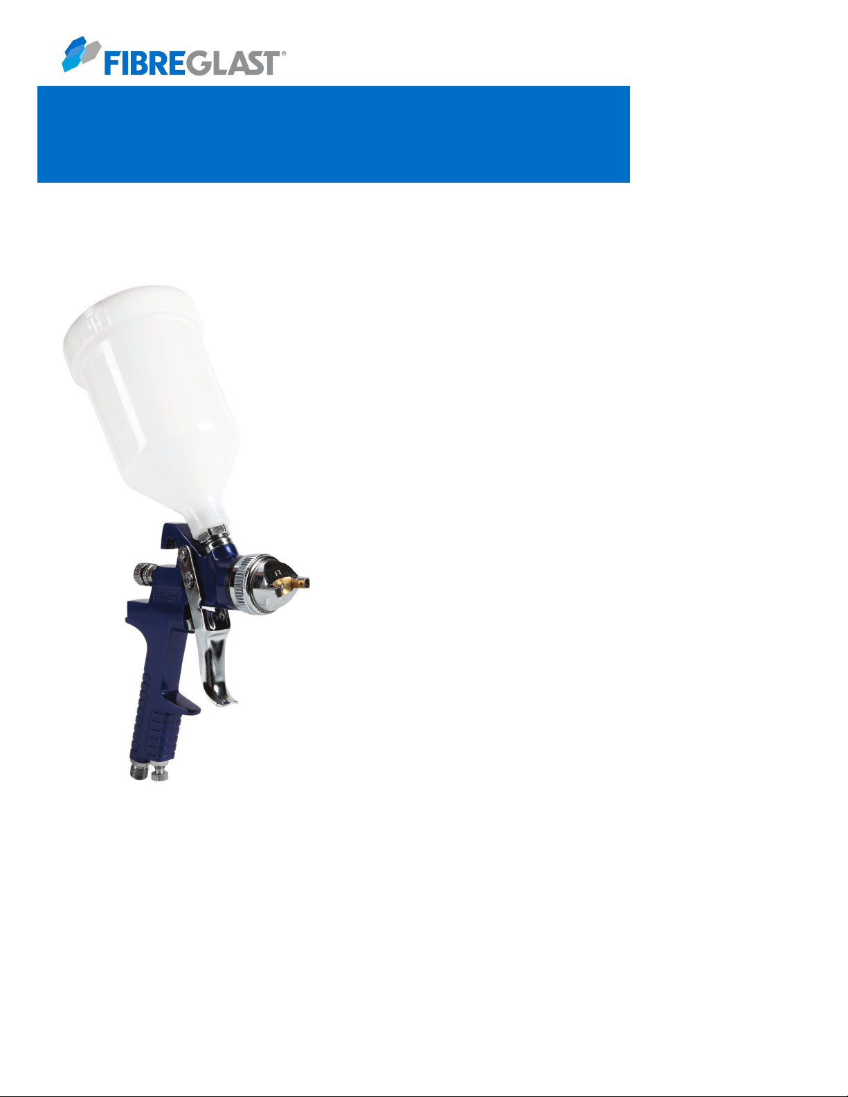
This is a heavy duty gun offering a range of adjustments that will allow
the spray pattern to be customized to the specific project. This gun excels
at large surface spraying, such as new mold construction, composite
refinishing andlarge boat repair.
This gun comes fitted with a 2.5mm nozzle, which is ideal for any of our
gel coats. Ships complete with 1.25 pint cup, cleaning brush, and 1 mini
filter.
Read this Instruction Manual carefully. Basic precautions should be
strictly followed to prevent the damage to the tool and injury to the
operator. Retain this manual for further reference.
.6 Liter (20 oz.) Touch Up Spray Gun
126

Information present herein has been compiled from sources considered to be dependable and is accurate and reliable to the best of our knowledge and belief but is not guaranteed to be so. Nothing
herein is to be construed as recommending any practice or any product violation of any patent or in violation of any law or regulation. It is the user’s responsibility to determine for himself the suitability
of any material for a specific purpose and to adopt such safety precautions as may be necessary. We make no warranty as to the results to be obtained in using any material and, since conditions of use
are not under our control, we must necessarily disclaim all liability with respect to the use of any material supplied by us.
© Copyright 2020 Fibre Glast Developments Corporation
Fibre Glast Developments Corporation
385 Carr Drive
Brookville, Ohio 45309
Phone: 800.214.8572
Fax: 937.833.6555
www.fibreglast.com
Feed Type
Standard Diameter of Nozzle
Recommended air pressure
Material Capacity
Air Consumption
Compressor Required
Air Connection
126-A
Gravity
2.5 mm
2.5 - 3.5 bar (40 - 80 psi)
.6 Liter (20 ounces)
4.7 - 7.1 cfm
1.5 H.P
1/4 n.p.t.
Important Safety Instructions
1. Certain materials can create toxic vapors, intoxication and serious damage to health. Always wear safety glasses,
gloves and respirator to prevent the toxic vapor hazard, or solvent and gel coat coming into contact with your eyes or
skin.
2. Never use oxygen, combustible or any other bottle gas as a power source to avoid explosion and serious personal
injury.
3. Fluid and solvent can be highly flammable or combustible. Use in wellventilated spray booth and avoid any ignition
sources, such as smoking, open flames and sparks.
4. Disconnect tool from air supply when not in use or maintaining also a shut off valve. As an emergency stop is
recommend.
5. Use clean, dry and regulated compressed air rated at 2.0-3.5 bar, (40-80PSI). Never exceed maximum permissive
operating pressure.
6. Never use homogenate hydrocarbon solvent, which can chemically react with aluminum and zinc parts and
chemically compatible with aluminum and zinc parts.
7. Never point gun at you or others at any time.
8. Before operating the tool, make sure all the screws & caps are securely tightened in case of leaking.
9. Before spraying, be sure the trigger and related parts operate smoothly.
10. Never modify this tool for any applications. Only use recommended parts, nozzles and accessories.
Features
126
Information present herein has been compiled from sources considered to be dependable and is accurate and reliable to the best of our knowledge and belief but is not guaranteed to be so. Nothing
herein is to be construed as recommending any practice or any product violation of any patent or in violation of any law or regulation. It is the user’s responsibility to determine for himself the suitability
of any material for a specific purpose and to adopt such safety precautions as may be necessary. We make no warranty as to the results to be obtained in using any material and, since conditions of use
are not under our control, we must necessarily disclaim all liability with respect to the use of any material supplied by us.
© Copyright 2020 Fibre Glast Developments Corporation
Fibre Glast Developments Corporation
385 Carr Drive
Brookville, Ohio 45309
Phone: 800.214.8572
Fax: 937.833.6555
www.fibreglast.com
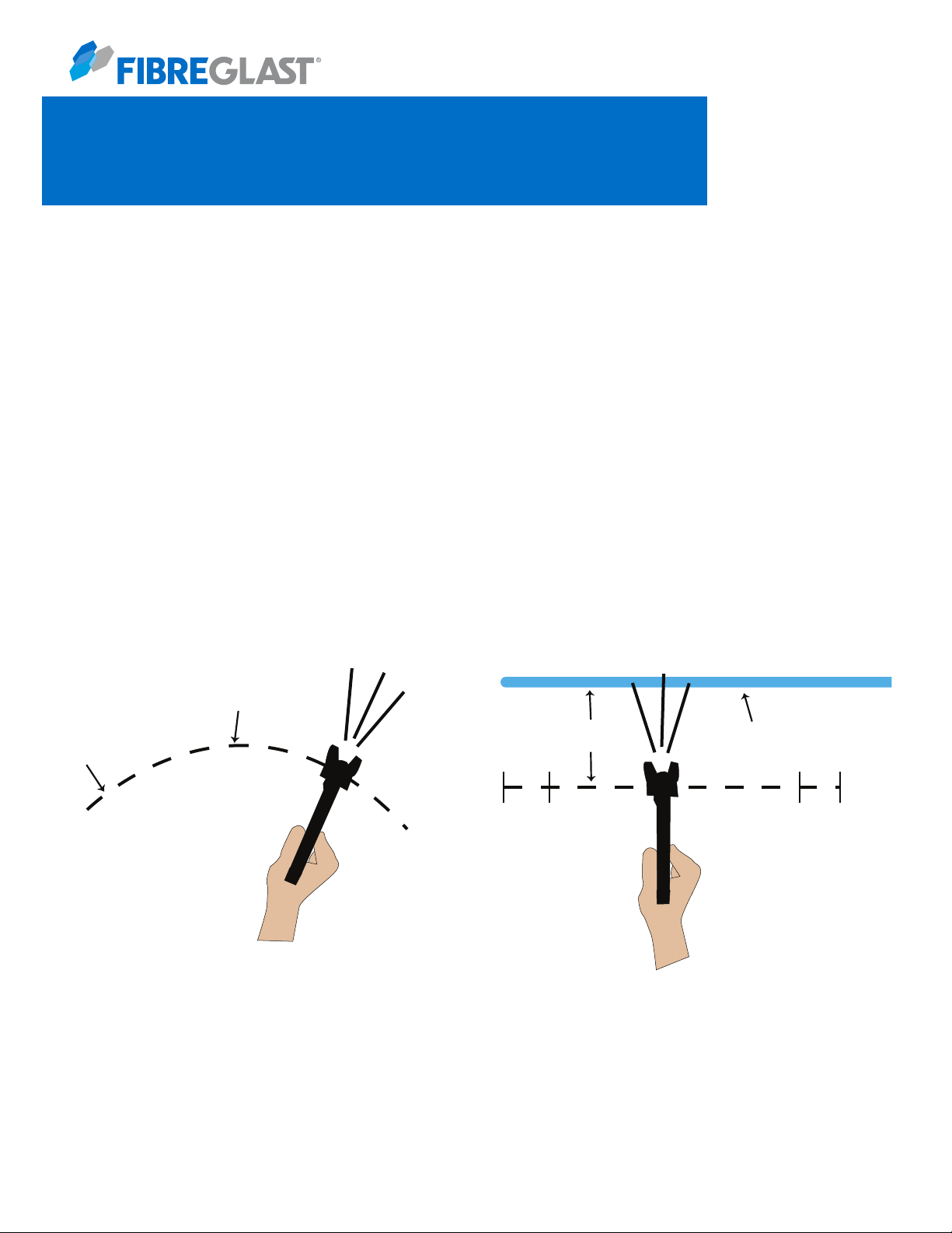
Wrong Right
Coating will
be light
at this point.
Coating will
be heavy
at this point.
6 to 12 inches
Start
stroke Pull
trigger
Coating should be even
and wet when spraying
Release
trigger
End of
stroke
Operating Instructions:
This tool operates on clean, dry, compressed air at regulated pressure at 40 - 80 PSI. Too low or too high pressure
will adversely affect the gun and the quality of spray.
Check and replace any damaged or worn parts on the tool. Make sure the trigger and nozzle can operate will.
Connect the gun to air supply. Be sure fluid cap, container and air hose should be connected tightly with spray gun.
When spraying, hold the gun perpendicular to spraying area, and then move it parallel several times. The trigger
should be locked before the stroke ended. Keep the appropriate distance of 6-12 inches between gun and surface
area, according to the atomization pressure and spraying conditions.
126
Information present herein has been compiled from sources considered to be dependable and is accurate and reliable to the best of our knowledge and belief but is not guaranteed to be so. Nothing
herein is to be construed as recommending any practice or any product violation of any patent or in violation of any law or regulation. It is the user’s responsibility to determine for himself the suitability
of any material for a specific purpose and to adopt such safety precautions as may be necessary. We make no warranty as to the results to be obtained in using any material and, since conditions of use
are not under our control, we must necessarily disclaim all liability with respect to the use of any material supplied by us.
© Copyright 2020 Fibre Glast Developments Corporation
Fibre Glast Developments Corporation
385 Carr Drive
Brookville, Ohio 45309
Phone: 800.214.8572
Fax: 937.833.6555
www.fibreglast.com
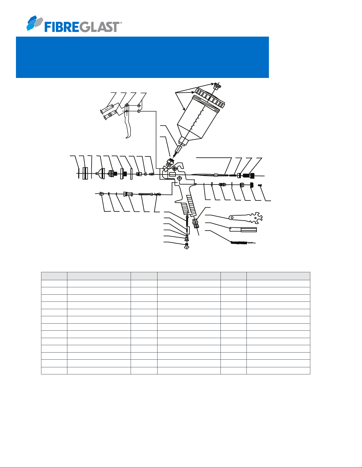
23 24 25 27 28P
28A
30
31
NK NK NK NK NK 18
12 11 10 09 18 07 06
45
44
NK 35 36 37
43 42 41 40 39 38
46
47
48
05
04
03
02
01
19 20 21 22
126-A Parts List - Available through Special Order Only
126
No
01
02
03
04
05
06
07
08
09
10
11
12
18
Description
Air Adj Knob
Air Adj Screw
Air Adj O-Ring
Air Adj Washer
Air Adj Spring
Air Inlet Valve
Switch Spring
Air Inlet Valve Body
Switch Knob
Swith Knob O-Ring
Switch Knob Washer
Lock Knob
Fluid Nozzle Joint
No
19
20
21
22
23
24
25
26
28 A
28 P
30
31
35
Description
Polypro Joint Washer
Direction Screw
Mat. Neddle Washer
Locking Spring
Trigger Lever 1
Trigger Lever 2
Trigger
Upper/Lower Snap Retainer
Alum Cup Assy (1.0 L)
Plastic Cup Assy (.06 L)
Material Filter
Mat Inlet Joint
Fluid Needle Spring
Description
Mat Lock Nut
Mat Adj Knob
Pattern Phillips Screw
Pattern Adj Knob
Pattern Adj Screw
Pattern Adj Washer
Pattern Adj Screw
Pattern Adj 0-Ring
Snap Retainer
Air Inlet Joint
Tool Wrench
Hex Wrench
Cleaning Brush
No
36
37
38
39
40
41
42
43
44
45
46
47
49

Information present herein has been compiled from sources considered to be dependable and is accurate and reliable to the best of our knowledge and belief but is not guaranteed to be so. Nothing
herein is to be construed as recommending any practice or any product violation of any patent or in violation of any law or regulation. It is the user’s responsibility to determine for himself the suitability
of any material for a specific purpose and to adopt such safety precautions as may be necessary. We make no warranty as to the results to be obtained in using any material and, since conditions of use
are not under our control, we must necessarily disclaim all liability with respect to the use of any material supplied by us.
© Copyright 2020 Fibre Glast Developments Corporation
Fibre Glast Developments Corporation
385 Carr Drive
Brookville, Ohio 45309
Phone: 800.214.8572
Fax: 937.833.6555
www.fibreglast.com
Troubleshooting
126
Symptom
Fluttering or Spitting
Pattern is arc
Pattern is not evenly spread
The center of the pattern is
too narrow
Pattern width of fan-shape
is not enough
Problems
1. Material level tool low
3. Loose fluid inlet connection
4. Loose or damaged fluid tip/ seat
1. Worn or loose Fluid nozzle
2. Material build up on air cap
1. Material build up on air cap
2. Fluid nozzle dirty or worn
1. Material too thin or not enough
2. Atomization air pressure too high
1. Material too thick
2. Atomization air
Solution
1. Add material into container
3. Tighten
4. Adjust or replace
5. Lubricate and or tighten
1. Tighten or replace fluid nozzle
2. Remove obstructions from holes, but don’t use
metal objects to clean it
1. Clean or replace air cap
2. Clean or replace fluid nozzle
1. Regulate material viscosity
2. Reduce air pressure
1. Regulate material viscosity

Information present herein has been compiled from sources considered to be dependable and is accurate and reliable to the best of our knowledge and belief but is not guaranteed to be so. Nothing
herein is to be construed as recommending any practice or any product violation of any patent or in violation of any law or regulation. It is the user’s responsibility to determine for himself the suitability
of any material for a specific purpose and to adopt such safety precautions as may be necessary. We make no warranty as to the results to be obtained in using any material and, since conditions of use
are not under our control, we must necessarily disclaim all liability with respect to the use of any material supplied by us.
© Copyright 2020 Fibre Glast Developments Corporation
Fibre Glast Developments Corporation
385 Carr Drive
Brookville, Ohio 45309
Phone: 800.214.8572
Fax: 937.833.6555
www.fibreglast.com
126
Gel Coat Troubleshooting Guide
Proper gel coat application is difficult for professionals and is probably the most common problem area for those new
to fiberglass work. Most common gel coat problems are related to temperature variation, catalyzation and a variety of
handling techniques. The following list of gel coat problems and causes should help to resolve some of the difficulties
associated with gel coat.
1. Wrinkles And Pinholes: A coating less than five mils thick may wrinkle, especially when brush marks are present.
Check the thickness using a gel coat thickness gauge. The preferred thickness is .010” to .020”. A wrinkle can also
occur if the gel coat is not cured enough prior to lay-up. Before lay-up check the surface for tack. The surface should
be sticky but not transfer to your finger. Several things can affect a slow cure; solvent or water entrapment, under
catalyzation, cold temperatures and other factors. If the gel coat film contains pinholes, check the spray equipment
for moisture in the air lines or dirt in the traps. It is also important to review your spray techniques.
2. Slow Gel Coat Cure: Any temperature below 70 degrees F will retard the gel time. An under-catalyzed gel coat will
also result in a slow cure but this is not a recommended technique for deliberately lengthening gel time. High
moisture and humidity will lengthen the gel time.
3. Sagging Of The Gel Coat: The most common reasons for gel coat sags would be when the gel coat is applied in an
excessively heavy application in one or more passes. To avoid sagging, spray in multiple light coats at a 15” distance
from the mold. The maximum thickness to be sprayed at one application is .016”.
4. Porosity: Gel coat porosity (air bubbles) is normally caused by trapped air or moisture. This can be prevented by
limiting the spray thickness per pass to .005”. It is also important to verify that the proper air pressure is being used
because an over pressurized spray can cause fine porosity. Air pressure should be set at 40-80 PSI, depending on
viscosity.
5. Separation Of Color: Most color separations are related to improper spray techniques. Reduce or lower thinning
agents and lower the per pass thickness of the gel coat. It is also important to avoid any spray overlap areas.
6. Discoloration On Finished Parts: This problem is caused from porosity related to air entrapment while spraying.
This can be overcome by spraying the mold surface with several light passes. It is also important to bleed any
moisture from the air lines and to be sure that the mold surface is dry.

Information present herein has been compiled from sources considered to be dependable and is accurate and reliable to the best of our knowledge and belief but is not guaranteed to be so. Nothing
herein is to be construed as recommending any practice or any product violation of any patent or in violation of any law or regulation. It is the user’s responsibility to determine for himself the suitability
of any material for a specific purpose and to adopt such safety precautions as may be necessary. We make no warranty as to the results to be obtained in using any material and, since conditions of use
are not under our control, we must necessarily disclaim all liability with respect to the use of any material supplied by us.
© Copyright 2020 Fibre Glast Developments Corporation
Fibre Glast Developments Corporation
385 Carr Drive
Brookville, Ohio 45309
Phone: 800.214.8572
Fax: 937.833.6555
www.fibreglast.com
126
Gel Coat Troubleshooting Guide, Continued
7. Craters And Pock Marks: These surface blemishes can be caused by improper resin to catalyst ratios and improper
air pressure both high and low. Another cause for craters would be oil or moisture on the surface of the mold.
8. Fisheyes: Fisheyes are usually caused by contaminates on the mold like dirt, moisture or oils. Bleeding the air lines
and using air filters will lower any air related contaminates. Try to isolate the spray area from any oils, especially
silicones.
9. Blisters When Immersed In Water: Blisters can be caused for the following reasons:
1. Incomplete cure
2. Improper wetting of the back up fibers
3. Bad bond between the gel coat and the back up laminate. This is often caused by contamination.
4. Thin gel coat
10. Lifting Of Gel Coat Before Laminating: This condition is usually related to shrinkage of the gel coat. Shrinkage can
be caused by:
1. Too fast of a curing time normally caused by over- catalyzation.
2. Delays between the gel coat and laminating can cause shrinking
3. Variations in gel coat thickness can vary the gel time which can cause shrinkage.
4. The mold surface is too hot.
11. Back Up Pattern Showing Through Gel Coat: This visual pattern is caused by too low a gel coat thickness or the
gel coat was not properly cured.
12. Gel Coat Sticking To The Part: This condition is caused by improper releasing of the mold surface. It is important
to use release agents formulated for the reinforced plastics industry. Proper training and common sense will
eliminate most of the problems associated with gel coats. Proper handling of gel coats will result in a part with a
blemish free surface.
Table of contents
Other Fibre Glast Paint Sprayer manuals


Popular Paint Sprayer manuals by other brands


Graco
Graco Optimiser 2K 02748 instructions

Graco
Graco VIBRA-FLO 17P002 Operation, parts

Worx
Worx HYDROSHOT WG620E Safety and operating manual

The Fountainhead Group
The Fountainhead Group SMITH PERFORMANCE NL403 use and care manual

Graco
Graco Ultra Max II 695 Operation manual

Graco
Graco ti2652a instructions


