Fike Cheetah Xi User manual

Cheetah Xi™ Enclosure
Installation Instructions
An ISO 9001-2000 Company
Fike®, 704 SW 10th Street, P.O. Box 610, Blue Springs, Missouri 64013-0610 U.S.A. ●Tel: (816) 229-3405 ●Fax: (816) 229-4615
While every precaution has been taken during the preparation of this document to ensure the accuracy of its content, Fike assumes no responsibility for errors or omissions.
Fike reserves the right to make changes to the product or this document without notice.
www.fike.com P/N 06-426 Rev. 1 page 1 of 4
DESCRIPTION
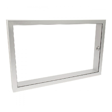
The Cheetah Xi™ enclosure (See Exhibit 1) is made
of 18 gauge steel with a baked on enamel finish (red
or black). It is designed so that it can be surface or
flush mounted. Numerous conduit knockouts are
provided on all four sides of the enclosure to
facilitate easy wiring access into the enclosure. The
knockouts allow connection of either ½” or ¾”
conduit. The removable exterior door is hinged on
the left side of the back-box and is equipped with a
key-lock to prevent unauthorized access to system
components.
Threaded press-studs are supplied in enclosure
back-box for easy installation of the following system
components (sold separately):
A. Cheetah Xi™ Controller (qty. 1)
B. AC Power Transformer (qty. 1)
C. Bosch FPT-DACT-LC, P/N 10-2528
D. Class A Peripheral Bus Card, P/N 10-2792*
E. Multi-Interface Module (MIM), P/N 10-2583*
F. Ethernet Module, P/N 10-2627*
G. Two 18 AH batteries (maximum)
*MIM, Ethernet module and Class A Peripheral Bus
card share a common mounting location. Only one
component can be installed at a time.
See Exhibit 2 for component layout within the
enclosure.
ENCLOSURE ORDERING
Part Numbers: 10-2541-c (c: R = Red, B = Black)
Weight: 16 lbs. (7.3 kg) empty
(door and back box)
SUPPLIED MOUNTING HARDWARE
The following mounting hardware is supplied with
the enclosure for future installation of the electronic
components. Store hardware inside the enclosure
after enclosure installation.
02-12025 Cabinet Keys (qty. 2)
02-12033 Standoff Kit
02-2715 M/F Standoff, .625” (qty. 5)
02-12014 Hardware Kit
4153-142 Lock Washer, #6 (qty. 2)
02-1361 6-32 Hex Nut (qty. 2)
02-4992 Ground Wire (qty. 1)
02-4035 Nut and star washer kit
(contains 20 nuts and washers)
Exhibit 1: Enclosure

Fike®, 704 SW 10th Street, P.O. Box 610, Blue Springs, Missouri 64013-0610 U.S.A. ●Tel: (816) 229-3405 ●Fax: (816) 229-4615
P/N 06-426 Rev.1 page 2 of 4 www.fike.com
MOUNTING LOCATION
The following guidelines shall be adhered to when
selecting the enclosure mounting location:
1. Mount the enclosure on a surface that is
vibration free, clean and dry.
2. Mount the enclosure in an area that is free from
sources of electromagnetic interference and
radio frequency interference; as these are types
of problems that could adversely affect the
successful operation and useful life of the
electronic equipment housed in the enclosure.
3. Mount the enclosure in an environment with a
nominal room temperature of 15°-27°C / 60° -
80°F, with a relative humidity of 85 percent.
4. Allow sufficient clearance around the enclosure
to allow the door to swing freely.
5. Mount the enclosure at a height that allows easy
access to system electronic components for
maintenance and service.
ENCLOSURE INSTALLATION
1. The enclosure’s outer door can be removed to
make installation of the back box easier. To
remove the outer door, unscrew the hinge
screws located at the top and bottom of the
enclosure.
2. Determine the quantity and size of conduit to be
attached to the enclosure and remove
appropriate knockouts. Knockouts provide for
attachment of ½” or ¾” conduit. Do not use
conduit knockouts located in the bottom of the
enclosure if installing batteries.
LNote: Fire Alarm System wiring is classified
as either power-limited or nonpower-limited
per NEC Article 760. All power-limited
wiring must be separated from all nonpower-
limited wiring by a minimum distance of ¼”
(6 mm). Refer to documentation provided
with each electrical component for
designation of power-limited versus
nonpower-limited circuits.
3. Mount the enclosure at the selected location.
See Exhibit 3 for enclosure dimensions.
Surface Mounting
Utilize the four tear-drop openings in the back of
the back box to secure it to the mounting surface
with suitable anchors.
Flush Mounting
Cut and frame an opening in the wall to fit the
back-box dimensions. Secure the box in place
utilizing the through holes provided on the sides
of the back box.
iCAUTION
The enclosure is NOT fire rated. Do not mount
on or in a fire rated wall unless wall is properly
framed to maintain specific fire rating.
4. Reinstall the outer door using existing mounting
hardware.
5. Connect the outer door grounding wire, as
shown in Exhibit 4, using the hardware provided.
Adjust routing of grounding wire as necessary to
allow full movement of outer door. Check for
continuity between door and back box.
6. If the enclosure was ordered with the optional
dead-front panel, refer to the documentation
supplied with the panel for installation
instructions.
LINE2
SYS TRBL
HEARTBEAT
LINE1
P7
P11
P10
P9
P8
P6
GG
B
A
C
D
E
F
Exhibit 2: Enclosure Layout

Fike®, 704 SW 10th Street, P.O. Box 610, Blue Springs, Missouri 64013-0610 U.S.A. ●Tel: (816) 229-3405 ●Fax: (816) 229-4615
www.fike.com P/N 06-426 Rev. 1 page 3 of 4
Exhibit 3: Enclosure Dimensions

Fike®, 704 SW 10th Street, P.O. Box 610, Blue Springs, Missouri 64013-0610 U.S.A. ●Tel: (816) 229-3405 ●Fax: (816) 229-4615
P/N 06-426 Rev.1 page 4 of 4 www.fike.com
OUTER DOOR
HINGE SIDE
BACK BOX
HINGE SIDE
#6-32 LOCK NUT
(2 PLACES)
GROUND WIRE (B)
P/N 02-4992
LOCK WASHER
P/N 4153-142
(2 PLACES)
OUTER DOOR
GROUNDING
STUD
A
BACK BOX
GROUNDING
STUD
A
Exhibit 4: Outer Door Ground Wire Installation
Other manuals for Cheetah Xi
2
Table of contents
Other Fike Enclosure manuals
