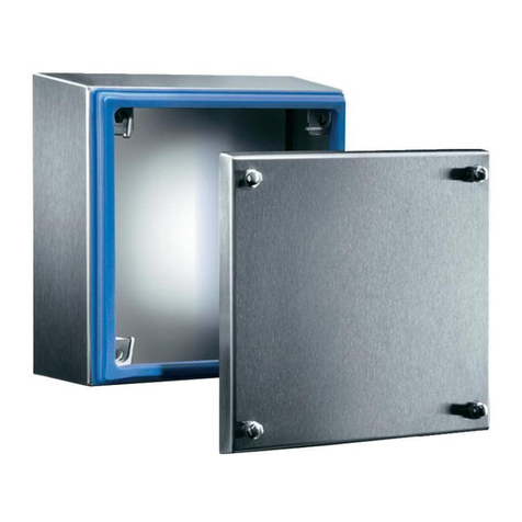
Fike 10-055-3-C User manual

Expanded Enclosures
Installation Guide
Manual P/N: 06-185
Revision No: 1, 11/01
THREE BAY
EXPANDED ENCLOSURE
10-055-3-C CHEETAH / SHP
10-060-3-C SHARK
TWO BAY
EXPANDED ENCLOSURE
10-055-2-C CHEETAH / SHP
10-060-2-C SHARK


FIKE CORPORATION
U.L. S2203 Expanded Enclosures Installation Guide Page i
F.M. 3009544 Manual P/N: 06-185 Revision No: 1, 10/01
Fike Corporation - Offices
Copyright Information
This document may not be reproduced, in whole or in part, by any means without the prior express written
permission of Fike Corporation.
Fikeis a registered trademark of Fike Corporation.
Disclaimers
The information contained in this manual is as accurate as currently possible. This manual is intended to be
an aid to Fike authorized sales outlets, who have been trained in an approved manner by Fike, and the user
who is a customer of the Fike authorized sales outlet. Fike does not warrant that this manual is technically
correct, complete, or free from writing problems or that the Fike products referenced therein are free from
minor flaws.
In accordance with our policy of continuing product and system improvement, Fike reserves the right to
change designs or specifications without obligation and without further notice.
Reader Responses
Fike encourages input from our sales outlets and end users on how we can improve this manual and the
products themselves. Please direct all calls of this nature to Fike’s Product Support Department
at (816) 229-3405.
Any communication received becomes the property of Fike Corporation.
Warranties
Fike provides a one-year limited manufacturer's warranty on this product. The standard warranty is printed in
each Marketing Price List. All warranty returns must be returned from an authorized Fike Sales outlet.
Contact Fike's Marketing Department for further warranty information. Fike maintains a repair department
that is available to repair and return existing electronic components or exchange/purchase previously repaired
inventory component (advance replacement). All returns must be approved prior to return. A Material Return
Authorization (MRA) number should be indicated on the box of the item being returned. Contact the
appropriate Regional Sales Manager for further information regarding Material Return Procedures.
Fike Corporation
World Headquarters
704 South 10th Street
P.O. Box 610
Blue Springs, Missouri 64013
U.S.A.
Ph: (816) 229-3405
Fax: (816) 229-5082
Fike South East Asia
81, Loyang Way
Singapore, 1750
Singapore
Ph: 011-65-545-1188
Fax: 011-65-545-2139
Fike Canada
4140 Morris Drive
Burlington, Ontario L7L 5L6
Canada
Ph: (905) 681-3100
Fax: (905) 681-3107
Fike Europe
Toekomstlaan 52
B-2200 Herentals
Belguim
Ph: 011-32-14-210031
Fax: 011-32-14-210743
Fike Latina
Avenida Paulista 2202, 3°, cj34
Cerqueira Cesar, Sao Paulo
Brazil, CEP 01310-300
Ph: 011-55-11-251-5244
Fax: 011-55-11-284-8479
Fike United Kingdom
10-11 Enterprise Estate
Moorfield Road
P.O. Box 540
Guildford, Surrey GU1 1RB
United Kingdom
Ph: 011-44-8700-777-540
Fax: 011-44-7000-777-540


FIKE CORPORATION
U.L. S2203 Expanded Enclosures Installation Guide Page ii
F.M. 3009544 Manual P/N: 06-185 Revision No: 1, 11/01
TABLE OF CONTENTS
Section Page
1.0 PREFACE......................................................................................................................................................1
1.1 About This Manual .....................................................................................................................1
1.2 Product Support .........................................................................................................................1
1.3 Revision History .........................................................................................................................1
1.4 Terms Used in this Manual ........................................................................................................1
1.5 Safety Notices ...........................................................................................................................2
2.0 PRODUCT OVERVIEW ............................................................................................................................... 3
2.1 Product Description....................................................................................................................3
2.2 Listings and Approvals ...............................................................................................................3
2.3 Agency Standards and Compliance....................................................................................... 3-4
2.4 Related Documentation..............................................................................................................4
2.5 Expanded Enclosure Features...................................................................................................4
3.0 EQUIPMENT PRODUCTS ............................................................................................................................5
3.1 Equipment/Products............................................................................................................... 5-7
3.2 Equipment/Products – Spare Parts............................................................................................8
3.3 Enclosure Specifications ...................................................................................................... 9-14
4.0 DESIGN .......................................................................................................................................................15
4.1 Identify Local Code Requirements...........................................................................................15
4.2 Identify Specification and End-User Customer Requirements ................................................15
4.3 Ensure Proper Mounting Location ...........................................................................................15
5.0 INSTALLATION ..........................................................................................................................................17
5.1 Install Backbox/Enclosure........................................................................................................17
5.2 Install Mounting Plates .............................................................................................................18
5.3 Install Miscellaneous Labeling .................................................................................................19
5.4 Install Internal Electronic Assemblies ................................................................................ 20-23


FIKE CORPORATION PREFACE
U.L. S2203 Expanded Enclosures Installation Guide Page 1 of 23
F.M. 3009544 Manual P/N: 06-185 Revision No: 1, 11/01
1.0 PREFACE
1.1 ABOUT THIS MANUAL
This manual is intended to be a complete reference for the overview and installation of the Fike
Expanded Enclosures. For specific instructions regarding wiring, refer to the specific Control Panel
Manual. This manual is intended for the designer and installer.
Before you refer to any section in this manual, and before you attempt to install or use the Fike
electronic hardware, be sure to read the important User Information that follows this explanation.
1.2 PRODUCT SUPPORT
If you have a question or encounter a problem not covered in this manual, you should first try to
contact the sales outlet that sold the protection system. Fike has a worldwide distribution network.
Each sales outlet sells, installs, and services Fike equipment. Look on the inside door, left-side, there
should be a sticker with an indication of the sales outlet who sold the system. If you can not locate
the sales outlet, please call Fike Customer Service for locating your nearest sales outlet, or go to our
web-site at www.fike.com. If you are unable to contact your installing sales outlet or you simply do not
know who installed the system you can contact Fike Product Support at (816) 229-3405, Monday
through Friday, 8:00 a.m. to 5:00 p.m. CST.
1.3 REVISION HISTORY
Document Title: Fike Expanded Enclosure Installation Guide
Document Reorder Number: 06-185
Revision Section Date Reason for Change
0 All Sections 02 / 01 Initial Release
1 All Sections 09 / 01 Added Shark Information
1.4 TERMS USED IN THIS MANUAL
The following terminology is used frequently in this manual:
Term Description
Non-Power Limited A circuit designation given for wiring purposes. The amount of current
flowing through the circuit is unlimited vs. being limited, or power-limited.
Power Limited A circuit designation given for wiring purposes. The amount of current
flowing through the circuit is limited vs. being unlimited, or non-power limited.
Press Stud The backbox, door, and mounting plates all have 6-32 thread mounting studs
installed into the metal at appropriate mounting locations. This provides a
sturdy location for securing the equipment.
Stand-off An aluminum or metal extension piece to provide spacing between mounting
assemblies. Fike chooses a 6-32 thread for its stand-off spacers. The
pieces are typically referred to by the type of connection at each end of the
part:
Male (M) – extension spacer with threaded screw end for use with
connecting hex nut or female end of an additional standoff
Female (F) – extension spacer with threaded insert end for use with
connecting to press stud or male end of an additional spacer.

PREFACE FIKE CORPORATION
Page 2 of 23 Expanded Enclosures Installation Guide U.L. S2203
Revision No: 1, 11/01 Manual P/N 06-185 F.M. 3009544
1.5 SAFETY NOTICES
Be certain to read all the following caution before installing or using this device. Accidental damage
to the device could result if this caution is not heeded!
CAUTION: The Expanded Enclosures are intended for mounting Fike manufactured
electronics control systems. This manual refers to only the mounting hardware,
but electronics are frequently shipped with the mounting hardware. Each
electonic control board contains static sensitive components. Handle the module
by the edges only and avoid touching the integrated components. Keep the
module in the protective static bags it was shipped in until time for installation.
Always ground yourself with a proper wrist strap before handling the module(s).
If the installer is grounded at all times, damage due to static discharge will not
occur. If the module requires repair or return to Fike, it must be shipped in an
anti-static bag.

FIKE CORPORATION OVERVIEW
U.L. S2203 Expanded Enclosures Installation Guide Page 3 of 23
F.M. 3009544 Manual P/N: 06-185 Revision No: 1, 11/01
2.0 PRODUCT OVERVIEW
2.1 PRODUCT DESCRIPTION
The Fike Expanded Enclosures, P/N 10-055-2-C (-3-C) and P/N 10-060-2-C (-3-C) provide two
“standard” panel enclosure sizes for the Cheetah, Shark and SHP Control Systems. Additional
hardware is also available to provide mounting for the Cheetah/VESDA HLI, VESDA LaserCompact,
Addressable Modules, and Batteries.
2.2 LISTINGS AND APPROVALS
Approval Agency File Number
Underwriters Laboratories S2203
Factory Mutual (FM) 3009544
California State Fire Marshall (CSFM) Planned
City of New York (MEA) Red Enclosures Only 0101057
2.3 AGENCY STANDARDS AND COMPLIANCE
This Fire Alarm Control Panel complies with the following NFPA standards:
NFPA 1 – Fire Prevention Code
NFPA 13 – Sprinkler Systems
NFPA 25 – Water-Based Fire Protection Systems
NFPA 70 – National Electrical Code, Article 300 Wiring Methods
NFPA 70 – National Electrical Code, Article 760 Fire Protective Signaling Systems
NFPA 72 – National Fire Alarm Code
NFPA 77 – Static Electricity
NFPA 101 – Life Safety Code
NFPA 110 – Emergency Standby Power Systems
Two Bay
Enclosure
P/N 10-055-2-C
or
10-060-2-C
Three Bay
Enclosure
P/N 10-055-3-C
or
10-060-3-C
29.0”
(73.66 cm)
15.25”
(38.74 cm)
43.0”
(
109.22 cm
)
15.25”
(
38.74 cm
)

OVERVIEW FIKE CORPORATION
Page 4 of 23 Expanded Enclosures Installation Guide U.L. S2203
Revision No: 1, 11/01 Manual P/N 06-185 F.M. 3009544
The installer should also be familiar with the following documents and standards:
UL 864 – Standard for Control Units for Fire Protective Signaling Systems
UL 1481 – Power Supplies for Fire Protective Signaling Systems
ULC – Standard CAN/ULC-S527-M87
Applicable Local and State Building Codes
Requirements of the Local Authority Having Jurisdiction
2.4 RELATED DOCUMENTATION
To obtain a complete understanding of the wiring for the SHP or Cheetah or to become familiar with
related functions in general, refer to the documentation listed in Table 2.4-1 below.
Document Title Part Number
Cheetah Manual 06-148
Shark Manual 06-180
SHP Manual 06-130
VESDA LaserCompact Installation Guide 06-189
2.5 EXPANDED ENCLOSURE FEATURES
•Optional door “unused opening” cover
plate secured by metal hardware
(Cheetah / SHP only)
•Optional Mounting Plate for a pair
of batteries, up to 18 Amp-Hour, used
to keep batteries off enclosure and
allow use of the bottom knock-outs
•Enclosure back box width (14.35”/ 36.45
cm) mounts easily between most
building studs
•Three-bay enclosure provides two
locations for panel display
•Easily removed door with only two
securing screws (top and bottom pivot
points)
•Two common backbox sizes for
multiple options
•Mounting for Cheetah, Shark, or SHP
Control System
•Optional Mounting Plate for 4” square
modules used in the Cheetah and
Shark control panels
•Optional Mounting Plate for Cheetah /
VESDA HLI and/or VESDA
LaserCompact
•Available in Red or Grey

FIKE CORPORATION EQUIPMENT
U.L. S2203 Expanded Enclosures Installation Guide Page 5 of 23
F.M. 3009544 Manual P/N: 06-185 Revision No: 1, 11/01
10-055-2-C / 10-060-2-C
Where C = R (Red)
G (Gray)
The basic two-bay enclosure combination provides the main
backbox and door for two bays of fire control system hardware.
Both bays include mounting studs for securing the chosen
hardware mounting plate. It is intended for the control panel to be
installed in the top bay. If not using mounting plates in the bottom
bay, the enclosure will be shipped with vinyl caps covering the
bottom bay press studs. Electrical knockouts are located on all
sides for wire entry.
10-055-3-C / 10-060-3-C
Where C = R (Red)
G (Gray)
The basic three-bay enclosure combination provides the main
backbox and door for three bays of fire control system hardware. The
Cheetah/SHP door has two openings and the Shark door has one
opening. The Cheetah/SHP control panel can be installed in either
the top or middle bay of the enclosure. The Shark Control panel
should be installed in the middle bay only. The unused opening on
the Cheetah/SHP door is to be covered using the cover plate P/N 02-
4832 (included with order). If not using mounting plates in the bottom
bay, the panel will be shipped with vinyl caps covering the bottom bay
press studs. Electrical knockouts are located on all sides for wire
entry.
3.0 EQUIPMENT/PRODUCTS
3.1 EQUIPMENT/PRODUCTS
The 10-055/10-060 Expanded Enclosures consists of a red or gray metal enclosure with removable
door. The enclosures may be flush or surface mounted. They include a 0.5” (1.27 cm) lip around
the back box to facilitate flush mounting. The control panels are available in versatile "2-bay" or “3-
bay” enclosures providing capability for the mounting of optional modules. Refer to the last pages of
this section for a complete detail of the specifications/dimensions.
The basic part numbers for the components covered in further detail in this section are as follows:
10-055-2-C 2 Bay Expanded Cheetah/SHP Enclosure where C=
10-060-2-C 2 Bay Expanded Shark Enclosure R for Red
10-055-3-C 3 Bay Expanded Cheetah/SHP Enclosure G for Gray
10-060-3-C 3 Bay Expanded Shark Enclosure
10-059-P Cheetah Control System where P =
10-057-P Shark Control System 1 for 120VAC
10-058-P SHP Control System 2 for 240VAC
10-2345 Optional Mounting Plate, Cheetah/VESDA High Level Interface (HLI)
10-2346 Optional Mounting Plate, VESDA LaserCompact
10-2347 Optional Mounting Plate, 4" Square Addressable Modules (up to 6 modules)
10-2348 Optional Mounting Plate, Battery (will hold up to 18AH battery pair)

EQUIPMENT FIKE CORPORATION
Page 6 of 23 Expanded Enclosures Installation Guide U.L. S2203
Revision No: 1, 11/01 Manual P/N 06-185 F.M. 300954
10-059-P Cheetah Control System
10-057-P Shark Control System
10-058-P SHP Control System
Where P = Power
1 = 120 VAC
2 = 240 VAC
This system includes the control panel, mounting plate,
and transformer. The AC terminal block is installed on the
plate. Necessary mounting hardware is included to install
the transformer and control panel. The SHP Control
System includes a clear polycarbonate plate.
SYSTEM
FIRE ALARM
Shark Keypad
Transformer
Mounting Plate
Cheetah Control Panel
10-059-P
SHP Control Panel
10-058-P
Shark Detector Board
10-057-P
or or
(All Assemblies)

FIKE CORPORATION EQUIPMENT
U.L. S2203 Expanded Enclosures Installation Guide Page 7 of 23
F.M. 3009544 Manual P/N: 06-185 Revision No: 1, 11/01
VESDA PC LINK HLI
10-2277 HLI
10-2345 Optional Mounting Plate,
Cheetah/VESDA High Level
Interface (HLI)
This kit provides a stainless steel mounting plate, mounting
hardware, 10-2277 Cheetah/VESDA High Level Interface
(HLI) printed circuit board assembly, 02-3053 RS-232 cable,
and Cheetah/VESDA interface manual. It is approximately
12” (30.5 cm) wide by 11” (27.94 cm) high.
10-2346 Optional Mounting Plate,
VESDA LaserCompact
This kit provides a stainless steel mounting plate and necessary
mounting hardware, to install a VESDA Compact unit, P/N 68-
040/68-041 (sold separately). Due to sampling pipe requirements
the plate must be mounted in the bottom bay of the two bay
enclosure and either the middle or bottom bay of the three bay
enclosure. Holes are provided on the enclosure to facilitate
exhaust requirements for the Compact unit. Use the supplied
grommets to cover the edges of the exhaust holes. It is
approximately 12” (30.5 cm) wide by 11” (27.94 cm) high.
10-2347 Optional Mounting Plate,
4” Square Addressable Modules
This kit provides a stainless steel mounting plate and necessary
mounting hardware to install up to six each 4" square modules
(sold separately) without covers. It is approximately 12" (30.5 cm)
wide by 13 1/2" (34.29 cm) high.
10-2348 Optional Mounting Plate, Battery
This kit provides a stainless steel mounting plate and necessary
mounting hardware for securing plate to enclosure. This plate will
support up to two each of 18 Amp-Hour batteries (sold separately).
It brings the batteries up off of the bottom of the enclosure to provide
accessibility to the bottom knock-outs on the enclosure. It is
approximately 12" (30.5 cm) wide by 11" (27.94 cm) high by 3 1/2"
(8.89 cm) deep.
Grommet
Qty. 2 for encl.
exhaust holes

EQUIPMENT FIKE CORPORATION
Page 8 of 23 Expanded Enclosures Installation Guide U.L. S2203
Revision No: 1, 11/01 Manual P/N 06-185 F.M. 300954
3.2 EQUIPMENT/PRODUCTS – SPARE PARTS
The following parts are for ordering replacements or spare parts:
Description Part Number
HLI Mounting Plate 70-1773
VESDA LaserCompact Mounting Plate 70-1774
4" Module Mounting Plate 70-1775
Battery Mounting Plate 70-1776
Cheetah / Shark / SHP Mounting Plate 70-1777
2-Bay Enclosure Door (Cheetah/SHP) 10-2409-C
3-Bay Enclosure Door (Cheetah/SHP) 10-2410-C
2-Bay Enclosure Door (Shark) 70-1771-C
3-Bay Enclosure Door (Shark) 70-1765-C
2-Bay Enclosure Backbox 70-1767-C
3-Bay Enclosure Backbox 70-1769-C
Key and Lock w/ Cam 02-1606
Fike Key (without Cam) 02-4983
¾” Star Washer for Key Lock 02-3828
Shark Logo 02-4837
Black Polycarbonate Plate 02-4832
Clear Polycarbonate Plate (SHP only) 02-10145
Vinyl Cap for unused press stud 02-4836
Grommet (VESDA LaserCompact) 02-4883
1 1/2" Standoff, M/F, #6-32 02-2593
1" Standoff, F/F, #6-32 (Transformer) 02-2178
1/2" Hinged Standoff, M/M, #6-32 02-2842
#6-32, Nut and Washer kit 02-4035
#6-32, Screw and Washer kit 02-4956
Touch-Up Paint (Not available from Fike)
Red-Sherwin Williams - #F63VXR9951-4343 Polane
2.8T Plus Polyurethane Enamel
Gray-Sherwin Williams - #F63VXA9975 Polane T
Plus Polyurethane Enamel

FIKE CORPORATION EQUIPMENT
U.L. S2203 Expanded Enclosures Installation Guide Page 9 of 23
F.M. 3009544 Manual P/N: 06-185 Revision No: 1, 11/01
3.3 ENCLOSURE SPECIFICATIONS
The Cheetah/SHP (3.3.1,3.3.3) and the Shark (3.3.2, 3.3.4) enclosures are identical except for the
door’s display cutout.
3.3.1 Two Bay Cheetah / SHP Enclosure
Mounting Methods: Surface - Using tear-drop openings in back of backbox
Flush - Includes ½ “ (1.27 cm) lip around backbox and removable door with
full swing
Weight: 21.5 lbs. (9.75 kg) empty
Over-all Dimension: 15.25” (38.74 cm) across x 29” (73.66 cm) tall x 4” (10.16 cm) deep, See
below for precise dimensions
4.00
5.51
11/16
1.75
BOTTOM VIEW
12.60
14.35
10.86
11.00
26.20
29.00
10.00
TYP.
FRONT VIEW
4.5
4.00
3.6
6.19
15.25
12.56
14.25
TOP VIEW
2.25 3.25 3.37 3.25
EKO:
1 1/8 x 7/8 TYP.
16 PLCS.
SIDE VIEW
OPTIONAL BATTERY,
ADDR. MODULES OR
VESDA COMPACT
MOUNTING PLATE
3/16" DIA. THRU HOLES
FOR INSTALLATION
2 EA. SIDE
OPTIONAL
CONTROL BOARD OR
ADDRESSABLE MODULE
MOUNTING PLATE
1.25 DIA.
TYP. 4 PLCS.
10.84
14.06
6.00 28.00
2.25 TYP.
.50 TYP.
4 SIDES
CABINET LIP
2.25
10-055-2-C
2 Ba
y
Cheetah / SHP Enclosure

EQUIPMENT FIKE CORPORATION
Page 10 of 23 Expanded Enclosures Installation Guide U.L. S2203
Revision No: 1, 11/01 Manual P/N 06-185 F.M. 300954
3.3.2 Two Bay Shark Enclosure
Mounting Methods: Surface - Using tear-drop openings in back of backbox
Flush - Includes ½ “ (1.27 cm) lip around backbox and removable
door with full swing
Weight: 21.5 lbs. (9.75 kg) empty
Over-all Dimension: 15.25” (38.74 cm) across x 29” (73.66 cm) tall x 4” (10.16 cm) deep,
See below for precise dimensions
4.00
5.51
11/16
1.75
BOTTOM VIEW
12.60
14.35
10.86
11.00
26.20
29.00
10.00
TYP.
FRONT VIEW
3.6
6.19
15.25
12.56
14.25
TOP VIEW
2.25 3.25 3.37 3.25
EKO:
1 1/8 x 7/8 TYP.
16 PLCS.
SIDE VIEW
OPTIONAL BATTERY,
ADDR. MODULES OR
VESDA COMPACT
MOUNTING PLATE
3/16" DIA. THRU HOLES
FOR INSTALLATION
2 EA. SIDE
OPTIONAL
CONTROL BOARD OR
ADDRESSABLE MODULE
MOUNTING PLATE
1.25 DIA.
TYP. 4 PLCS.
10.84
14.06
6.00 28.00
2.25 TYP.
.50 TYP.
4 SIDES
CABINET LIP
2.25
10-060-2-C
2 Ba
y
Shark Enclosure

FIKE CORPORATION EQUIPMENT
U.L. S2203 Expanded Enclosures Installation Guide Page 11 of 23
F.M. 3009544 Manual P/N: 06-185 Revision No: 1, 11/01
3.3.3 Three Bay Cheetah / SHP Enclosure
Mounting Methods: Surface - Using tear-drop openings in back of backbox
Flush - Includes ½ “ (1.27 cm) lip around backbox and removable door with
full swing
Weight: 26.5 lbs. (12.02 kg) empty
Over-all Dimension: 15.25” (38.74 cm) across x 43” (109.22 cm) tall x 4” (10.16 cm) deep, See
below for precise dimensions
OPTIONAL
CONTROL BOARD OR
ADDRESSABLE MODULE
MOUNTING PLATE
40.20
3/16" DIA. THRU HOLES
FOR INSTALLATION
2 EA. SIDE
11/16
14.35
BOTTOM
1.75
10.86
12.60
5.51
4.00
43.00
FRONT
10.00
TYP.
4.5
OPTIONAL BATTERY,
ADDR. MODULES OR
VESDA COMPACT
MOUNTING PLATE
15.00
SIDE
14.00
12.00
1.25 DIA.
TYP. 6 PLCS.
14.00 42.00
EKO:
1 1/8 x 7/8 TYP.
24 PLCS.
4.00
.50 TYP.
4 SIDES
CABINET LIP
12.56
3.6
6.19
11.00
3.25
15.25
14.25
TOP
3.25
2.25 3.37
4.00
TYP.
2.25
10-055-3-C
3 Bay Cheetah / SHP Enclosure

EQUIPMENT FIKE CORPORATION
Page 12 of 23 Expanded Enclosures Installation Guide U.L. S2203
Revision No: 1, 11/01 Manual P/N 06-185 F.M. 300954
3.3.4 Three Bay Shark Enclosure
Mounting Methods: Surface - Using tear-drop openings in back of backbox
Flush - Includes ½ “ (1.27 cm) lip around backbox and removable
door with full swing
Weight: 26.5 lbs. (12.02 kg) empty
Over-all Dimension: 15.25” (38.75 cm) across x 43” (109.22 cm) tall x 4” (10.16 cm) deep,
See below for precise dimensions
10-060-3-C
3 Bay Shark Enclosure
OPTIONAL
CONTROL BOARD OR
ADDRESSABLE MODULE
MOUNTING PLATE
.50 TYP.
4 SIDES
CABINET LIP
5.51
1.75
4.00
12.60
14.35
10.86
43.00
11.00
15.25
14.25
12.56
2.25 3.373.25 3.25
42.00
3/16" DIA. THRU HOLES
FOR INSTALLATION
2 EA. SIDE
1.25 DIA.
TYP. 6 PLCS.
14.00 15.00
14.00 12.00
EKO:
1 1/8 x 7/8 TYP.
24 PLCS.
2.25
TYP.
4.00
10.00
TYP.
40.20
TOP
FRONT
BOTTOM
SIDE
OPTIONAL BATTERY,
ADDR. MODULES OR
VESDA COMPACT
MOUNTING PLATE
11/16
6.19
3.6

FIKE CORPORATION EQUIPMENT
U.L. S2203 Expanded Enclosures Installation Guide Page 13 of 23
F.M. 3009544 Manual P/N: 06-185 Revision No: 1, 11/01
2.75
.50
2.25
.50
2.50
3.53
3.13
.50
1.33
11.83
3.38
.63
1.44
1.85
12.94
11.00
9.65
6.75
10.00
1.72
3.42 6.50
5.50
4.70
0.98
3.3.5 Mounting Plate Assemblies
All mounting plate assemblies include hardware for mounting the plate to the back box. Also
included is mounting hardware for installing electronic components. Reference Section 5.2
for mounting plate installation.
•Plate Assembly for Cheetah / Shark /
SHP Control Panel
10-059-1 (-2) – Cheetah
10-060-1 (-2) – Shark
10-058-1 (-2) – SHP
1. Stainless Steel Plate with
terminal strip installed.
2. Transformer
3. Control Panel
4. Nut and Washer Kit
Weight: 2 Lbs (907.18 grams) plus
Transformer
•Plate Assembly, High Level Interface Board
P/N: 10-2345
1. Stainless Steel Plate
2. Nut and Washer Kit
3. Screw and Washer Kit
Weight: 2 Lbs (907.18 grams)
•Plate Assembly, VESDA LaserCompact Unit
P/N: 10-2346
1. Stainless Steel Plate
2. Nut and Washer Kit
3. 2 Grommets, Flexible
Weight: 1 Lb (453.6 grams)
0.50 TYP. 11.00
11.00
12.00
3.40
1.18 9.65
3.80
10.00
2.14
1.00
9.0011.00
12.00
11.00
1.20
0.30
3.15
10.00

EQUIPMENT FIKE CORPORATION
Page 14 of 23 Expanded Enclosures Installation Guide U.L. S2203
Revision No: 1, 11/01 Manual P/N 06-185 F.M. 300954
10.00
11.00
3.75
3.09.00
0.75
12.00
11.00 0.55
•Plate Assembly, Addressable Modules
P/N: 10-2347
*One plate will support six modules
1. Stainless Steel Plate
2. 12 Standoffs, M/F, #6-32 x 1.5”
3. 12 Standoffs, F/F, #6-32 x 1”
4. 12 Hinge Standoffs, M/M, #6-32 x .5”
5. Nut and Washer Kit
Weight: 2 Lbs
•Plate Assembly for Batteries
P/N: 10-2348
1. Stainless Steel Plate
2. Nut and Washer Kit
Weight: 2 Lbs
TYP.
3.38
1.75
10.0013.50
3.25 TYP.
TYP.
1.00
3.38
1.19 TYP.
11.00
12.00
TYP.
0.50
This manual suits for next models
3
Table of contents
Other Fike Enclosure manuals
