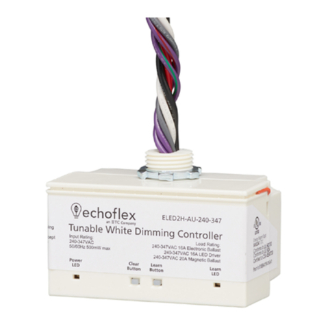
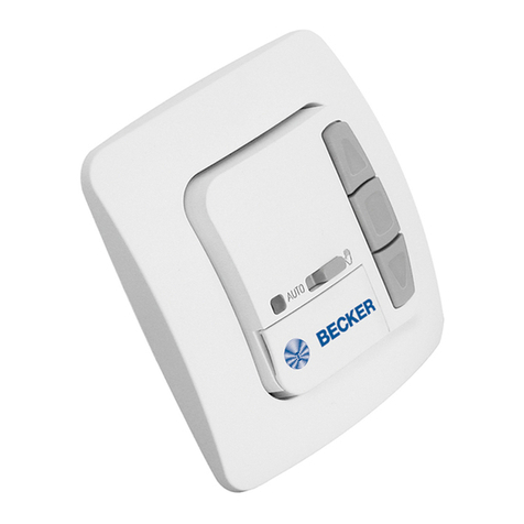
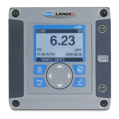
Filtration Group MFS-05 User manual

Translation of the original instructions
Filter controller MFS-05 ∆p
Material No. of Instruction Manual
70303409

Page 2
Translation of the original instructions MFS-05 Δp, Filtration Group GmbH, 16.01.18, Mat. No. 70303409, Version 03
1 Contents
1Contents...................................................................... 2
2General safety instructions....................................... 2
2.1 Safety instructions for installation and
operating personnel.......................................... 2
2.2 Warning structure.............................................. 2
2.3 Warning symbols used...................................... 2
2.4 Other symbols used:......................................... 3
3Glossary...................................................................... 3
4General information................................................... 3
4.1 Manufacturer..................................................... 3
4.2 Information about the Instruction Manual.......... 3
4.3 ATEX type key.................................................. 3
5Intended application .................................................. 4
6Main components....................................................... 4
6.1 Overview of types ............................................. 4
6.2 Controls, LEDs and displays............................. 4
7Technical data............................................................ 6
8Transport and storage............................................... 7
9Functions.................................................................... 7
9.1 Operating modes .............................................. 7
9.1.1 Interval time control ............................... 7
9.1.2 Switching threshold................................ 8
9.1.3Time control........................................... 8
9.2 Secondary functions ......................................... 9
9.2.1 Enable/stop (post-cleaning)................... 9
9.2.2 Rapid cleaning....................................... 9
9.2.3 Fault acknowledgement......................... 9
9.2.4 Pressure switch ..................................... 9
9.2.5 Cleaning signal...................................... 9
9.2.6 Alarm threshold ................................... 10
10 Installation................................................................ 10
10.1 Unpacking....................................................... 10
10.2 Installation procedure...................................... 10
10.3 Electrical connection....................................... 10
10.4 Start-up........................................................... 10
11 Shut-down................................................................. 10
12 Normal operation ..................................................... 11
13 Troubleshooting....................................................... 11
13.1 Test................................................................. 11
13.2 Troubleshooting table ..................................... 11
14 Maintenance, repair and retrofitting....................... 12
15 Appendix: Connection variants.............................. 13
15.1 Interval time and switching threshold control.. 13
15.2 Terminal assignment....................................... 14
16 Appendix: RS 485 serial port .................................. 15
17 Appendix: Set of instrument lines and protective
filter (ID No. 78341984).................................................. 16
18 Appendix: Dimension drawing MFS-05 Δp ............ 17
19 Appendix: Default settings...................................... 18
19.1 Main parameters of the MFS-05 Δp in
“interval time control” mode ............................ 18
19.2 Other operating modes................................... 18
19.2.1 “Switching threshold” mode................. 18
19.2.2 “Time control” mode............................. 18
20 Declaration of incorporation................................... 19
21 Declaration of conformity........................................ 20
22 Index.......................................................................... 24
2 General safety instructions
2.1 Safety instructions for installation and
operating personnel
This Instruction Manual contains important safety
instructions which must be heeded at all times during
installation, operation and maintenance. Non-observance
can result in risks to persons and the environment as well
as in damage to the machine or system, e.g.:
Failure of critical functions of the system or its
component parts.
Danger to persons from electrical or mechanical effects
as well as from chemical reactions.
Danger to the environment owing to the leakage of
hazardous substances.
Before installation/start-up:
•Read the Instruction Manual carefully.
•Make sure that installation and operating personnel are
adequately trained.
•Make sure that the contents of the Instruction Manual
are fully understood by the responsible persons.
•Define areas of responsibility and competence.
During operation of the system:
•Keep the Instruction Manual handy at the place where
the system is used.
•Heed the safety instructions.
•Always operate the system/machine in accordance with
its ratings.
If in doubt:
•Consult the manufacturer.
2.2 Warning structure
Where possible, warnings are structured according to the
following system:
Signal word
Possibly
with
symbol
Nature and source of the danger
Potential consequences of non-
observance.
•Action to avert the danger.
2.3 Warning symbols used
DANGER!
Immediate danger!
Non-observance will result in serious or fatal injury.
WARNING!
Potentially dangerous situation!
Non-observance can result in serious or fatal injury.
CAUTION!
Potentially dangerous situation!
Non-observance can result in minor or moderate
injuries.
CAUTION!
Potentially dangerous situation!
Non-observance can result in property damage.

Page 3
Translation of the original instructions MFS-05 Δp, Filtration Group GmbH, 16.01.18, Mat. No. 70303409, Version 03
2.4 Other symbols used:
Danger from high voltage
Danger information about explosion
protection
Information about environmental protection
Wear protective clothing!
Wear goggles!
Hand symbol:
Indicates general information and
recommendations
•
Bullet:
Indicates the order in which actions are to be
carried out
Arrow:
Indicates responses to actions
3 Glossary
Pulsing:
Pressure cleaning of the filter elements with air or gas.
“Switching threshold” pulsing:
Pulsing is activated when a switching threshold is
exceeded.
“Time-controlled” pulsing:
Pulsing is activated at fixed time intervals.
Switching threshold:
Preset differential pressure that must not be exceeded or at
which a defined action, such as activation of a valve, must
take place.
Temperature hysteresis:
Response inertia to a change in temperature.
Temperature drift:
Temperature sensitivity of the transistor characteristics.
4 General information
4.1 Manufacturer
Filtration Group GmbH
Schleifbachweg 45
D-74613 Öhringen
Phone +49 7941 6466-0
Fax +49 7941 6466-429
fm.de.sales@filtrationgroup.com
www.filtrationgroup.com
4.2 Information about the Instruction Manual
FG Mat. No.:........................................................70303409
Date: .....................................................................16.01.18
Version: ..........................................................................03
4.3 ATEX type key
II
3
D
T60°C
IP65
1.
2.
3.
4.
5.
1.
II
Valid for use above ground
2.
Category
2
Use in
Zone 22
3.
Atmo-
sphere
G = Gas
D= Dust
D
4.
Maximum surface temperature 60°C
5.
Degree of protection IP65

Page 4
Translation of the original instructions MFS-05 Δp, Filtration Group GmbH, 16.01.18, Mat. No. 70303409, Version 03
5 Intended application
DANGER!
The MFS-05 Δp filter controller must not be
operated in potentially explosive atmosphere
(Zones 0, 1 and 2).
DANGER!
This filter controller is only allowed to be used in
accordance with the operating conditions specified in the
contract documentation and in the Instruction Manual.
All forms of use which deviate from or exceed the limits of
use described above are considered to be contrary to the
intended purpose.
The manufacturer shall not be liable for any damage
resulting from such use.
The MFS-05 ∆p filter controller with integrated differential
pressure transmitter is used for demand based control of
cleaning systems of the kind encountered in industrial dust
removing applications. Up to 24 automatically actuated
diaphragm valves pulse the dust elements.
Numerous control and monitoring functions are
implemented in the controller.
The MFS-05 ∆p filter controller normally operates
according to the “interval time control” principle. The
variable interval time between valve actuations is
calculated from a characteristic curve according to the
differential pressure. Alternatively, the controller can be
operated in “switching threshold” or “time-controlled” mode.
Valve monitoring:
All valves are monitored for overcurrent (short-circuits) and
interruptions. The controller has three relays for
operating/fault signals, cleaning signals and “alarm
threshold exceeded”.
6 Main components
0,1
0,3
0,6
1,0
1,5
1,5
2,0
2,5
3,0
5
20
50
100
200
350
500
1
2
3
4
5
6
7
8
9
10
11
12
Puls Pause Ventile Nachrein
TEST
S1
4 5 6 7 10 13811 14912 15
25 26 27 28 31 3429 32 3530 33 36
42 43 44 45 48 5146 49 5247 50 53
54 55 56 57 60 6358 61 6459 62 65
18 19 20
39 40 41
16 17 20 21 22 23
37 38 66 67 68
1 2 3
F1
13 14 15 16 17 18 19 20 21 22 23 24
1 2 3 4 5 6 7 8 9 10 11 12
Ventilanzeige
Störung
(rot)
Betrieb
(grün)
Reinigung
(gelb)
XS1
69 70
T
0
9
8
7
6
5
4
3
2
1
0
12
11
1
10
2
3
4
5
6
9
8
7
Fig. 1: Controls, LEDs and displays
6.1 Overview of types
The order numbers in parentheses apply to
units that are packed and ready for shipping.
MFS-05 ∆p AC 230 V
76341440 (76341838)
MFS-05 ∆p DC 24 V
76341457 (76341846)
Accessories:
Valve extension
13 to 24 valves
79742982 (76109664)
Replacement fuses
(pack of 5)
76186597 (76186605)
Set of instrument lines
with protective filter
78341984 (79759846)
6.2 Controls, LEDs and displays
LC display:
Fig. 2: LC display
3-digit, 7-segment display showing the current differential
pressure or the switching threshold.
Display selection:
Fig. 3: Display selection
Position
Display
0
Current differential pressure [mbar]
1
Cleaning cycles
2
High threshold
3
Alarm threshold
4
Not assigned
5
Current valve or faulty valve
(in this case, the first digit is a blinking line):
Down = interruption
Up = overcurrent
6
Post-cleaning cycles
7
No. of valves
8
Interval time
9
Pulse time
Potentiometers:
The time settings have a logarithmic scale with a control
range of 240°.

Page 5
Translation of the original instructions MFS-05 Δp, Filtration Group GmbH, 16.01.18, Mat. No. 70303409, Version 03
On the motherboard:
Pulse time
0.1 s ... 3.0 s
Interval time
5 s ... 500 s
No. of valves
1 ... 12 valves
13 ... 24 valves if a valve extension
board is installed
If the number of valves is set to an
intermediate value, two adjacent valve
LEDs blink
Post-cleaning
cycles
0 ... 12
If the number of cycles is set to an
intermediate value, the complete LED
row blinks
0
12
11
1
10
2
3
4
5
6
9
8
7
Fig. 4: Controls on the motherboard:
On the ∆P module:
Cleaning cycles
1 … 10
High threshold
0 ... 40 mbar
Alarm threshold
0 ... 40 mbar
Fig. 5: Controls on the Δp module
Zero:
The ∆p zero adjusting screw is located to the right of the
LC display.
Fig. 6: Zero adjustment
Jumper XS1:
Fig. 7: Factory setting for interval time control
Pressure
switch*
Analogue
input
Cleaning
mode
Cleaning
cycle
Desig-
nation
Nein/ja
DS
(press-
ure
switch
yes/
no)
0/4 -
20 mA
Schw./
Reg
(threshol
d/control)
T/G Cycle
(partial/
full cycle)
Yes
4 – 20 mA
Interval
time
control
Full cycle
No
0 – 20 mA
High
threshold
Partial
cycle
* Function not supported
TEST button S1:
Press this button to start cleaning the next valve for the
duration of the set pulse time.
Fig. 8: TEST button S1

Page 6
Translation of the original instructions MFS-05 Δp, Filtration Group GmbH, 16.01.18, Mat. No. 70303409, Version 03
LEDs:
Fault (red)
Operation (green)
Cleaning (2 x yellow)
Pulsing (red, 1x per valve)
Alarm threshold on ∆P module (red)
Fig. 9: LEDs
Valve alarm LED:
Valve LED blinks.
Cause: Overcurrent or interruption
7 Technical data
The inputs are not isolated!
•Provide external isolation if necessary.
Fig. 10: Nameplate
Analogue inputs
(not isolated)
•Start or Δp input not assigned
(time control: 16-17 jumpered)
Digital inputs
•Enable (contact closed, terminal
18-19) / stop (contact open)
•Post-cleaning
•Rapid cleaning
•Fault acknowledgement
(momentary contact signal)
Pressure
measuring lines
•P1 = pressure on
dirty side = [+]
(upstream of filter element)
•P1 = pressure on
clean side = [-]
(downstream of filter element)
•Measuring hose diameter: 4 mm
Valve outputs
12, extendable to 24
Valve voltage
24 V DC ± 10%
Valve current
1 A for pulse time ≤ 1 s,
otherwise 0.5 A
Relay outputs
•Contact load 250 V AC / 5 A
•1 changeover contact for
operating/fault signals
(FAIL-SAFE circuit)
•1 NO contact for cleaning signal
•1 changeover contact for ∆p alarm
Analogue output
•0 (4) ... 20 mA
∆p sensor
•Measuring range: 0 ... 40 mbar
•Max. static pressure: 1 bar
•Linearity: ±1%
•Temperature hysteresis: ±0.5%
•Temperature drift / zero:
±0.025% / K
•Temperature drift / upper range
value:
±0.01% / K
Time settings
•Pulse time: 0.1 ... 3.0 s
•Interval time: 5 ... 500 s
•Post-cleaning: 0 ... 12 cycles
LEDs
•Operation: Green
•Cleaning: Yellow
•Fault: Red

Page 7
Translation of the original instructions MFS-05 Δp, Filtration Group GmbH, 16.01.18, Mat. No. 70303409, Version 03
•Valve alarm: Red
•Alarm threshold: Red
Electrical
connection
•Screw-type terminal strips
2.5 mm²
•Valve connections 1.0 mm²
Ambient
temperature
0 ... 50°C
Climatic
category
KWF acc. to DIN 40040
(≤ 75% relative humidity, no
condensation allowed)
Design
•Dust-tight Makrolon casing
(Ex II 3D T60°C IP65)
•175 x 175 x 100 mm (W x H x D)
Mains power supply
230 V AC,
50-60 Hz
24 V DC
Tolerance
±10%
±10%
Mains fuse
0.315 A time-
lag
3.15 A time-
lag
Power consumption
30 W
42 W
8 Transport and storage
Transport
•Always transport in the original packaging
•Avoid vibrations
Storage
•Always store in the original packaging
•The unit must be stored in a dry room at 0 … 70°C
•Avoid vibrations
•Avoid direct UV radiation (sunlight)
9 Functions
9.1 Operating modes
The controller can operate in three different modes. The
mode is selected by altering the assignment of terminal
16-18 and the setting of the “XS1” jumper.
9.1.1 Interval time control
If “interval time control” mode is selected, the controller is
permanently active. The interval time varies as a function
of ∆p.
Factory settings:
•Terminal 16-17 not assigned
•Terminal 18-19 jumpered
•XS1 jumper Schw./Reg. switch up
•XS1 jumper T/G Cycle switch up
Fig. 11: Jumper settings for interval time control
Valve activation is controlled by a ∆p-dependent interval
time.
The interval duration is determined by Δp and the
selected controller characteristic.
Possible controller characteristics:
04812 16 20 24 28 32 36 40 mbar2
aus ein
Fig. 12: Controller characteristics
Example:
The filter must be cleaned at a differential pressure
equivalent to 30% of the differential pressure measuring
range (= 12 mbar) with an interval time of approximately
70 s.
To select the characteristic:
•Find and plot the 30% line.
•Find and plot the 70 s line.
The point of intersection is located on characteristic 60.
•Set the “interval” potentiometer to 60 s.

Page 8
Translation of the original instructions MFS-05 Δp, Filtration Group GmbH, 16.01.18, Mat. No. 70303409, Version 03
0
12
11
1
10
2
3
4
5
6
9
8
7
Fig. 13: “Interval” potentiometer
The controller determines the required interval time from
the current differential pressure and the selected
characteristic.
The interval time is shorter if the differential pressure
increases and longer if it is reduced.
The change in the interval time is non-linear.
The cleaning process ends if the differential
pressure falls below approximately 5% of the
measuring range.
9.1.2 Switching threshold
If “switching threshold” mode is selected, the controller is
activated when the set threshold is exceeded.
Factory settings:
•Terminal 16-17 not assigned
•Terminal 18-19 jumpered
•Jumper 3 down
Full cycle (optional)
•XS1 jumper T/G Cycle switch up
A full cycle is executed if the switching threshold is
exceeded.
Fig. 14: Jumper settings for full cycle
Partial cycle (optional):
•XS1 jumper T/G Cycle switch down
A cleaning process is executed if the switching threshold
is exceeded.
The cleaning process ends if the differential pressure
falls below the switching threshold.
The next valve is activated when the controller is
activated again.
Fig. 15: Jumper settings for partial cycle
9.1.3 Time control
Factory settings:
•Terminals 16-17 and 18-19 jumpered
•Both pressure measuring lines disconnected
•XS1 jumper Schw./Reg. switch down
Fig. 16: Jumper settings for time control
A time-controlled cleaning process starts if contacts 16-17
and 18-19 are closed.

Page 9
Translation of the original instructions MFS-05 Δp, Filtration Group GmbH, 16.01.18, Mat. No. 70303409, Version 03
9.2 Secondary functions
9.2.1 Enable/stop (post-cleaning)
The input (terminal 19) enables valve activation (terminals
18 + 19 are jumpered).
•Set the number of post-cleaning cycles with the
post-cleaning potentiometer.
The closed contact opens.
An automatic post-cleaning process starts with an
interval time of 30 s.
0
12
11
1
10
2
3
4
5
6
9
8
7
Fig. 17: Post-cleaning potentiometer
9.2.2 Rapid cleaning
•Close the switching contact (terminals 18 and 20).
A cleaning process starts with an interval time of 8 s.
9.2.3 Fault acknowledgement
If a fault occurs, the red fault LED lights up.
•Find the fault.
•Rectify the fault.
•Acknowledge the fault by applying a momentary contact
signal at terminals 18 and 21.
The fault signal is reset.
Fig. 18: Fault
9.2.4 Pressure switch
The pressure switch settings are not
supported. The pressure switch jumper on the
XS1 switch should always be down.
Fig. 19: Jumper settings for pressure switch
9.2.5 Cleaning signal
The yellow cleaning LED lights up during a cleaning
process.
The yellow cleaning LED lights up if the test button S1
is pressed.
The yellow cleaning LED goes out again at the end of
the cleaning process.
Fig. 20: Cleaning

Page 10
Translation of the original instructions MFS-05 Δp, Filtration Group GmbH, 16.01.18, Mat. No. 70303409, Version 03
9.2.6 Alarm threshold
•Set the alarm threshold with the alarm potentiometer.
The red alarm LED lights up if the alarm threshold is
exceeded.
The alarm relay is switched.
Fig. 21: Alarm threshold and alarm LED
10 Installation
DANGER!
The system is only allowed to be installed,
accepted and tested by a suitably qualified
person (99/98/EC).
WARNING!
All installation work must be carried out by suitably
qualified personnel!
10.1 Unpacking
WARNING!
Risk of damage to the unit!
Safe operation can be impaired.
•Inspect the MFS-05 ∆P for damage. Return to FG for
maintenance if necessary.
•Remove the MFS-05 ∆p filter controller from the
packaging.
•Check the separately enclosed accessories (Instruction
Manual, fastening elements) for completeness.
10.2 Installation procedure
The controller must be installed in a dry, low-dust room.
The ambient temperature at the place of installation must
not exceed the maximum value specified in the data sheet
for the nominal range of use.
•Ensure adequate heat dissipation (especially if several
units are installed together with a high packing density).
•Provide the necessary sealing components (e.g. seals)
for the specified degree of protection.
10.3 Electrical connection
We recommend using twisted and screened
instrument lines to prevent interference from
interference fields.
•The electrical connection should correspond to the
connection/terminal diagrams for the unit concerned.
•All electrical wiring should be laid in accordance with the
relevant EMC specifications as well as any nationally
valid regulations (VDE 0100 in Germany).
•Instrument lines should be laid separately from signal
and power leads.
•The protective conductor terminal (inside the instrument
rack) must be connected to a protective earth conductor.
•Install a suitable main switch.
10.4 Start-up
Check the following points before switching on the unit:
•The supply voltage must be identical the voltage
indicated on the nameplate.
•The contact protection covers must be fitted.
•The unit is only allowed to be operated when installed.
Class I units:
•The protective conductor terminal inside the instrument
rack must be conductively connected to the protective
earth conductor.
If the unit is interconnected with other units and/or
equipment, the possible consequences should be
considered before it is switched on and appropriate
precautions taken.
11 Shut-down
•Switch off the auxiliary power.
•Protect the unit against inadvertent operation.
If the unit is interconnected with other units and/or
equipment, the possible consequences should be
considered before it is switched on and appropriate
precautions taken.
•Either switch off the system with the motor
circuit-breaker or shut it down on the machine controller.
•All parts must be disposed of in a
manner which does not pollute the
environment.
Emergency shut-down
•Switch OFF the main switch.
The power supply is interrupted.

Page 11
Translation of the original instructions MFS-05 Δp, Filtration Group GmbH, 16.01.18, Mat. No. 70303409, Version 03
12 Normal operation
The green ‘operation’ LED lights up when the unit is
switched on.
The unit is now ready.
Fig. 22: Operation LED
•The yellow LED lights up if the differential pressure
is > 5% (> approx. 2 mbar) and the valves are
activated.
The controller is active.
13 Troubleshooting
13.1 Test
•Press the S1 test button in the top right-hand corner of
the controller to switch the valves.
•A settable differential pressure must be supplied for the
duration of the test.
Alternatively:
•Test the controller in “time control” mode
(terminals 16-17 and 18-19 jumpered).
13.2 Troubleshooting table
Fault
Possible cause
Remedy
Green
‘operation’
LED not lit
Power supply
faulty
Test the voltage
Fuse F1 defective
Replace the fuse
Yellow
LED not lit
No start signal
Check the differential
pressure
No signal enable
18-19 jumpered
Jumper XS1 set
incorrectly
Check the jumper
settings
Both red
valve
LEDs blink
Valve
potentiometer
inadvertently
altered
Set the potentiometer
correctly
One red
LED blinks
Valve not switched
Test the valve cable
Potentiometer set
incorrectly
Potentiometer setting =
no. of valves
Red LED
lit
Valve not activated
Test the valve
connection
Acknowledge the fault
Terminal 18 + 21
Red LED
row blinks
Post-cleaning
potentiometer
inadvertently
altered
Set the post-cleaning
potentiometer correctly

Page 12
Translation of the original instructions MFS-05 Δp, Filtration Group GmbH, 16.01.18, Mat. No. 70303409, Version 03
14 Maintenance, repair and retrofitting
CAUTION!
Danger if work is carried out on the system by
unauthorised persons!
Risk of injury.
•All maintenance work must be carried out by
SUITABLY QUALIFIED PERSONNEL.
The filter controller does not require any special
maintenance.
CAUTION!
Electrostatic discharge
Components which are sensitive to
electrostatic discharge (ESD) may be
exposed when the units are opened.
•In this case, all subsequent work is only
allowed to be carried out at workplaces
that are protected against electrostatic
discharge.
During retrofitting:
If the unit is tampered with during the
warranty period, all warranty claims
are rendered invalid.
•Switch off the filter controller.
•Take steps to prevent the system from being switched
on again by unauthorised persons.
•Take any necessary safety precautions
•Carry out the maintenance work.
•Start up the filter controller again.
•Observe the filter controller.
Does it operate normally?
•Check whether any of the values indicated on the
nameplate need to be altered/corrected.
•Correct this data if necessary.
If a fuse blows:
•Determine and rectify the cause.
•Install a replacement fuse with the same ratings as the
original fuse.
•The use of rewired fuses is prohibited, as is short-
circuiting the fuse holder.
•
•

Page 13
Translation of the original instructions MFS-05 Δp, Filtration Group GmbH, 16.01.18, Mat. No. 70303409, Version 03
15 Appendix: Connection variants
15.1 Interval time and switching threshold control

Page 14
Translation of the original instructions MFS-05 Δp, Filtration Group GmbH, 16.01.18, Mat. No. 70303409, Version 03
15.2 Terminal assignment
123
12316 17 18 19 20 21 22 23 24
45678910 11 12 13 14 15
25 26 27 28 29 30 31 32 33 34 35 36
42 43 44 45 46 47 48 49 50 51 52 53
54 55 56 57 58 59 60 61 62 63 64 65
37 38 39 40 41 66 67 68 69 70
B
RS 485
+-+-+-+ - + - + -
+-+-+-+ - +-+ -
+ - +-+-+-+ - +-
+ - + - +-+ - + - +-
+-+-
PE
24 V DC
230 V DC
Valve extension
A
Lag/Discharge Δp Alert
25 mA
Start
GND (-DP-In)
Release/Stop/
Post-cleaning
0(4)...20 mA
Output
Rapid-cleaning
Malfunction
acknowledgement
+: common potential
-: switched output
Valve 1 Valve 2Valve 3Valve 4Valve 5Valve 6
Valve 7
Valve 13
Valve 19
Valve 8
Valve 14
Valve 20
Valve 9
Valve 15
Valve 21
Valve 10
Valve 16
Valve 22
Valve 11
Valve 17
Valve 23
Valve 12
Valve 18
Valve 24
Malfunction/
operation

Page 15
Translation of the original instructions MFS-05 Δp, Filtration Group GmbH, 16.01.18, Mat. No. 70303409, Version 03
16 Appendix: RS 485 serial port
The controller has an RS 485 serial port that can be used to query the current unit settings on a PC, for example.
Data format:
1 start bit, 8 data bits, no parity, 1 stop bit
Baud rate:
19200 baud
Protocol:
The data is queried by sending one byte (‘A’, ‘B’, etc.) to the controller. The controller responds with one
word (16 bits). This response must be converted to the appropriate measurement unit by the PC.
Connection:
Terminal 69: RS 485 B
Terminal 70: RS 485 A
Query Response Calculation Unit Comments
20 mA input
“A” 65 hex
0-1020
x / 45
mA
Start input
Configuration
“B” 66 hex
0-1020
Not possible, see program version
Configuration 2
“C” 67 hex
0-1020
Not possible, see program version
Pulse
“D” 68 hex
0-1020
(((x div 4)² div 44) * 2 +100) / 1000
s
Interval
(potentiometer)
“E” 69 hex
0-1020
(((x div 4)² div 64) +10) / 2
s
Valves
“F” 70 hex
0-1020
(x+46) / 92 + 0.5
Post-cleaning
“G” 71 hex
0-1020
((x div 4)² div 53) / 10
min.
<1 minute = off
Lag time
“H” 72 hex
0-1020
∆p
“I” 73 hex
0-1020
X/204
V
0 ... 5 V = measuring
range
Inputs
“J” 74 hex
0-31
2^0 = Enable
2^1 = Rapid cleaning
2^2 = Fault acknowledgement
2^3 = Pressure switch
2^4 = Test button
Program
version
“K” 75 hex
16000
(x div 32) / 100 + 45
2^0 = 4 mA
2^1 = Pressure switch
2^2 = Pressure switch version
2^3 = Full cycle
2^4 = Controller
Current interval
time
“L” 76 hex
20-2052
x / 4
s
Valve alarm
“M” 77 hex
0-248
2^0-2^4 = Valve
2^5 = Interruption
2^6 = Overcurrent
2^7 = Pressure monitoring
Alarm threshold
“N” 78 hex
High threshold
“O” 79 hex
Low threshold
“P” 80 hex
Display
selection
“Q” 81 hex
Δ p measuring
range
“R” 82 hex
Δ p reference
“S” 83 hex
Δ p da
“T” 84 hex
Other
characters
32000
Unknown query
div = Integer division with no remainder

Page 16
Translation of the original instructions MFS-05 Δp, Filtration Group GmbH, 16.01.18, Mat. No. 70303409, Version 03
17 Appendix: Set of instrument lines and protective filter (ID No. 78341984)
To measure the differential pressure:
•Connect the sensor to the measuring points upstream and downstream of the filter plate using the instrument lines.
•The instrument lines should be protected and laid without any kinks.
•No condensate must be allowed to accumulate on the instrument lines. Provide a condensate trap if necessary.
•No dust protection is necessary for the cleaned gas line.
Leaking or dirty lines can lead to measurement errors and malfunctions.
Fig. 23: Installation drawing and spare parts
Elbow bulkhead screw
fitting for hose
OD 6 mm
77974413
Instrument line
Hose PU/4 black
78238248
Screw-on connection
G 1/4“
77940166
Sealing ring PVDF
76141188
Filter plate
Hole ∅13.5 mm
Casing
Hole 2 x Ø14 mm
Nipple G 1/4"
78342024
Membrane filter Ti 56
Bottom side coated
78342032
Snap ring
15x1 DIN 472 1.4310
77749500
+
-

Page 17
Translation of the original instructions MFS-05 Δp, Filtration Group GmbH, 16.01.18, Mat. No. 70303409, Version 03
18 Appendix: Dimension drawing MFS-05 Δp
Fig. 24: Connection diagram for optional pressure switch

Page 18
Translation of the original instructions MFS-05 Δp, Filtration Group GmbH, 16.01.18, Mat. No. 70303409, Version 03
19 Appendix: Default settings
19.1 Main parameters of the MFS-05 Δp in “interval time control” mode
Parameter
Comments
Factory setting
Operation
No. of valves Refer to section 6 for information about settings N
Interval potentiometer Controller characteristic, section 10.9 60
Pulse time Pressure cleaning
Rotating wing 0.1 s
1.5 s
Post-cleaning cycles 0
Alarm threshold 18 mbar
Terminal assignment See circuit diagram Jumper 18-19
Jumper settings Schw./Reg. jumper Up
T/G Cycle jumper Up
19.2 Other operating modes
19.2.1 “Switching threshold” mode
Parameter
Comments
Factory setting
Operation
Jumper settings Schw./Reg. jumper Down
T/G Cycle jumper Up
High threshold 14 mbar
Cleaning cycles 1
Terminal assignment See circuit diagram Jumper 18-19
Jumper settings Schw./Reg. jumper Down
T/G Cycle jumper Up
19.2.2 “Time control” mode
Parameter
Comments
Factory setting
Operation
Terminal assignment Terminals 16-17 and 18-19 jumpered
Interval time 600 divided by the number of valves n xx
Jumper settings Schw./Reg. jumper Down
T/G Cycle jumper Up

Page 19
Translation of the original instructions MFS-05 Δp, Filtration Group GmbH, 16.01.18, Mat. No. 70303409, Version 03
20 Declaration of incorporation
As defined by the EC Machinery Directive.

Page 20
Translation of the original instructions MFS-05 Δp, Filtration Group GmbH, 16.01.18, Mat. No. 70303409, Version 03
21 Declaration of conformity
Table of contents

