ARAG Bravo 3 Series User manual

BRAVO 3XX
SOFTWARE 60 VERSION
ADDITION TO INSTRUCTION BOOKLET CODE D20033.GB

This manual is an integral part of the device to which it refers and must always accompany it, even
in case of sale or transfer. Keep it for future reference; ARAG reserves the right to modify the spe-
cifications and instructions regarding the product at any time and without prior notice.
2

3
Contents
1 INTRODUCTION................................ 4
1.1 New functions .......................................4
2 SETTINGTHEFUNCTIONS.......................... 5
2.1 Setting the minimum and maximum nozzle pressure alarms ...............5
2.2 Incorrect operating pressure signal ............................6
2.3 Setting the minimum speed of adjustment ........................7
2.4 Setting the minimum speed for the automatic closure of the main valve .........8
2.5 Calibration of 0 for the pressure transducer .......................10
2.6 Resetting the liquid present in the tank .........................11
2.7 Display of the "FIELD 0" counters ............................12
2.8 Pump failure signal ...................................13
3 MULTIROW SPRAYER PROGRAMME FUNCTIONS . . . . ........14
3.1 Main differences compared to the version for the spraying machine ..........14
3.2 Programming of the flow rate for the sectors ......................15
3.3 Selection of the flow rate of the sectors .........................16
3.4 Setting the operating widths ...............................17
3.5 Selection of the operating width .............................18
3.6 Setting the operating programmes ........................... 19
3.7 Selection of the operating programmes .........................20
4 ORCHARD SPRAYER PROGRAMME FUNCTIONS. . . . . . . . . . . . . 21
4.1 Main differences compared to the version for the spraying machine ..........21
4.2 Programming the flow rate of the sprayer booms ....................22
4.3 Selection of the flow rate of the sprayer booms .....................23
4.4 Selection/modification of row distance .........................24
4.5 Configuration of operating programmes .........................25
4.6 Selection of operating programmes ........................... 26
4.7 Signalling of ambiguous section opening ........................26

English
1 INTRODUCTION
This introduction booklet explains the different functions of the 60 software compared to the 54 software.
The main changes in the software affect operation when the BRAVO 3XX computer is set as a multi-row
sprayer or orchard sprayer.
1.1 New functions
The main changes are:
• Setting the minimum and maximum nozzle pressure alarms (section 2.1):
the minimum and maximum pressures can be set for correct operation of each nozzle: the computer will
trigger an alarm signal outside these limits.
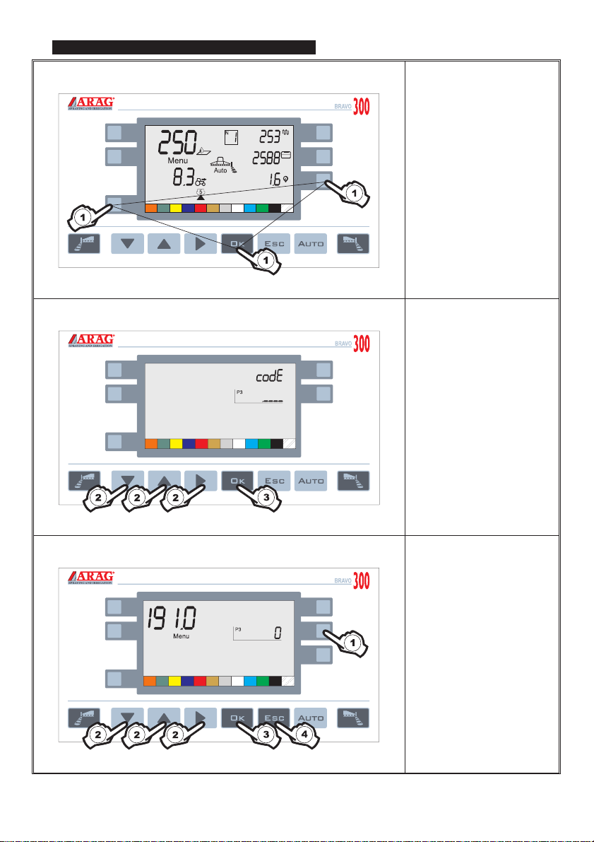
• Setting the minimum speed for adjustment (Menu 191.0 section 2.3):
It is possible to set a minimum speed so that automatic adjustment will not triggered below it.
This makes it possible to remain within a range of pressure so that the nozzles always provide effective
coverage.
IATTENTION: below this speed, dosing no longer corresponds to the preset amount
•Setting the minimum speed for the automatic closure of the main valve
(Menu 191.0 - 192.1 section 2.4):
it is possible to set a speed so that the main valve will be closed automatically below this (only for
systems with separated unit, item code 46732XX)
IATTENTION: this function AUTOMATICALLY excludes the setting of the minimum adju
-
stment speed (Menu 191.0 section 2.3)
•Incorrect operating pressure signal (section 2.2):
the computer triggers an alarm signal when the nozzle operating pressure does not correspond to the
preset level.
• Calibration of 0 for the pressure transducer (section 2.5):
the reading of 0 of the pressure transducer can be calibrated, if necessary.
• Resetting the liquid present in the tank (section 2.6):
the quantity of liquid in the tank can be reset rapidly.
• Display of the "FIELD 0" counters (section 2.7):
it is possible to display the data with more than 4 or 5 digits relating to field 0 (field can not be reset).
•Pump failure signal (section 2.8):
when the sensor signals pump failure, the computer triggers a visual and acoustic alarm signal.
4

English
2 SETTING THE FUNCTIONS
2.1 Setting the minimum and maximum nozzle pressure alarms
1) Keep pressed until you
access menu 1.0
2) Press to select
menu 4.0
(see following illustration)
MENU 4.0
3) Press to select the
nozzle whose pressure
alarms require setting
4) Keep pressed until you
access the menu for
setting the alarms relative
to the nozzle selected
(see following illustration)
FOLLOWING
5

5) Press to access
modification of the
minimum pressure level,
below which an alarm will
be triggered (visual and
acoustic)
6) Press to access
modification of the
maximum pressure level,
above which an alarm will
be triggered (visual and
acoustic)
7) Press to return to
menu 4.0
During data modification:
A) Press to modify the data
you are setting
B) Press to confirm the new
data entered
2.2 Incorrect operating pressure signal
Should the operating
pressure be above or below
the limits set for the nozzle
in operation, the two
symbols will flash and an
acoustic signal will be
heard
English
6

2.3 Setting the minimum speed of adjustment
1) Keep all the buttons
pressed together in order to
access advanced user
programming
2) Press to set code 76
3) Press to confirm the
code
MENU 191.0
1) Press to set the value for
the minimum speed, below
which automatic adjustment
will be blocked
2) Set the required value
3) Press to confirm the data
4) Press to return to the
main menu
5) Switch the computer off
and on again for the
settings to take effect
English
7

2.4 Setting the minimum speed for the automatic closure of the main valve
1) Keep all the buttons
pressed together in order to
access advanced user
programming
2) Press to set code 76
3) Press to confirm the
code
MENU 191.0
1) Press to set the value for
the minimum speed (km/h
or mph), below which
automatic delivery will be
closed
2) Set the required value
3) Press to confirm the data
English
8

1) Press to select
menu 192.1
MENU 192.1
1) Press to set the delay
(in sec) for the closure of
the main valve: after the
speed has dropped below
the minimum value set in
menu 191.0, the computer
will close the main valve
after the delay, set
previously, is over.
ATTENTION:
If the value 0 is set,
automatic closure of the
valve is cancelled
2) Set the required value
3) Press to confirm the data
4) Press to return to the
main menu
5) Switch the computer off
and on again for the
settings to take effect
English
9

2.5 Calibration of 0 for the pressure transducer
1) Keep pressed until you
access the calibration
menu for the calibrated
returns
(see following illustration)
2) Press to access the 0
calibration menu for the
pressure transducer
(see following illustration)
ATTENTION: If the
computer has not been
programmed to manage
calibrated returns, the
display here aside will not
appear and you will go
directly to the pressure
transducer calibration
menu
(see following illustration)
3) Press until the acoustic
signal is heard confirming
that calibration of the
pressure transducer has
been completed
ATTENTION: Make sure
the pressure of the
system is zero before
starting calibration.
4) Press to return to the
main menu
English
10

2.6 Resetting the liquid present in the tank
1) Keep pressed until you
access the menu for filling
the tank
(see following illustration)
2) Press to access setting
for the liquid present in the
tank
3) Press both buttons
together in order to reset
the value for the remaining
liquid shown by the
computer
4) Press to confirm
resetting; you will
automatically return to the
previous menu
English
11

2.7 Display of the "FIELD 0" counters
1) Keep pressed until you
access the menu for
selection of the field
(see following illustration)
2) Press to select "FIELD 0"
3) Press to display the
meter totals in succession:
•Distance travelled
•Time worked
•Hectares treated
•Liquid delivered
Example 1:
The display here aside
indicates that 2532588
litres or gallons of product
have been delivered
FOLLOWING
English
12

Example 2:
The display here aside
indicates that a distance of
15 km or miles has been
travelled
2.8 Pump failure signal
Should pump failure be
detected, these symbols
will be displayed and an
acoustic alarm signal will
be heard
English
13

3 MULTIROW SPRAYER PROGRAMME FUNCTIONS
3.1 Main differences compared to the version for the spraying machine
This software enables 5 different operating widths to be stored, in order to minimise the time required to
carry out settings when treating plots of land with different widths between rows.
This function has resulted in the modification or addition of new menus or procedures:
•Programming the flow rate of the sectors (Menu 5.0, section 3.2):
possibility to programme 5 different flow rate combinations for the individual sections;
these values must be entered:
- so that the calculation of pressure will be correct;
- so that automatic adjustment functions correctly when you use the pressure transducer instead of the
flow meter.
•Selection of the flow rate of the sectors (section 3.3)
•Setting the operating widths (Menu 6.0 / 6.1, section 3.4):
this menu is used to store 5 operating widths (Menu 6.0 - Cnf X);
for each of these, the operating width must be entered for each individual sector (Menu 6.1).
•Selection of the operating width (section 3.5):
a previously set operating width can be selected when programming the applied volume (Cnf X).
•Setting the operating programmes (section 3.6):
this function is used to set 12 different operating programmes.
•Selection of the operating programmes (section 3.7):
the button, which is used for selecting the previously set nozzle on the sprayer machine, is used for
selecting an operating programme (also preset) on the multi-row sprayer version; the operating
programme is the combination of operating width/dosing.
•User programming:
programming of the nozzle flow rate values (Menu 4.0) has been replaced by programming of the flow
rates for the individual sectors (Menu 5.0).
English
14

3.2 Programming of the flow rate for the sectors
1) Keep pressed until you
access menu 1.0
2) Press the buttons to
select menu 5.0
(see following illustration)
MENU 5.0
1) Press to select which of
the 5 configurations
requires modification
2) Press to select the
sector whose flow rate
requires setting
3) Press to set the flow rate
value for the selected
sector
4) Press to set the pressure
value relating to the flow
rates entered
ATTENTION: the
reference pressure is the
same for all the
configurations
During data modification:
A) Press to modify the data
you are setting
B) Press to confirm the new
data entered
English
15
2 2

3.3 Selection of the flow rate of the sectors
1) Keep pressed until you
access menu 1.0
2) Press the buttons to
select menu 5.0
(see following illustration)
MENU 5.0
3) Press to select which of
the 5 configurations is to be
used
4) Press to confirm
selection
English
16

3.4 Setting the operating widths
1) Keep pressed until you
access menu 1.0
2) Press the buttons to
select menu 6.0
(see following illustration)
MENU 6.0
1) Press to access
selection of the
configuration to be modified
2) Press to select the
number of the configuration
to be modified
3) Press to confirm the
configuration to be modified
4) Press to access the
modification of the selected
configuration
MENU 6.1
1) Press to select the
section to be modified
2) Press to access
modification of the selected
section
3) Press to modify the
operating width relating to
the section that is being set
4) Press to confirm the
value entered
5) Press to return to
menu 6.0
English
17

3.5 Selection of the operating width
1) Keep pressed until you
access the menu for the
selection of dosing (l/ha)
and the operating width
(see following illustration)
2) Press to set the dosing
amount (l/ha) to be applied
3) Press to modify the
operating width
During data modification:
A) Press to modify the data
you are setting
B) Press to confirm the new
data entered
English
18

3.6 Setting the operating programmes
1) Keep pressed until you
access the menu for the
selection of the operating
programme
(see following illustration)
2) Press to select the
operating programme for
configuration
3) Press to set the dosing
(l/ha) that is to be
associated with the
operating programme
selected
4) Press to access
selection of the operating
width to be associated with
the operating programme
selected
During data modification:
A) Press to modify the data
you are setting
B) Press to confirm the new
data entered
English
19

3.7 Selection of the operating programmes
1) Keep pressed until you
access the menu for the
selection of the operating
programme
(see following illustration)
2) Press to select one of
the 12 operating
programmes (previously
set)
3) Press to confirm
selection of the operating
programme
English
20
This manual suits for next models
1
Table of contents
Other ARAG Controllers manuals
Popular Controllers manuals by other brands

Aurora
Aurora AU-A1ZBSCCX quick start guide

Muller Elektronik
Muller Elektronik SPRAYER-Controller Orchard/Vineyard MIDI 3.0 operating instructions

AirCom
AirCom R10-S operating manual

Pool Technologie
Pool Technologie Pro Dosing Ampero Instructions for use

Adaptec
Adaptec 39320D user guide

NovaStar
NovaStar VX2U user manual