Fimas 104.41-1109 User guide

. . . . . . . . . . . . . . . . . . . . . . . . . . . . . . . . . . . . .
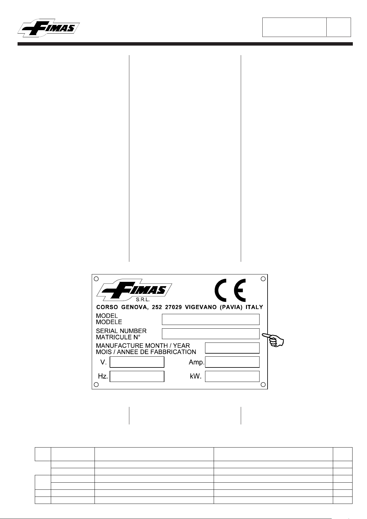
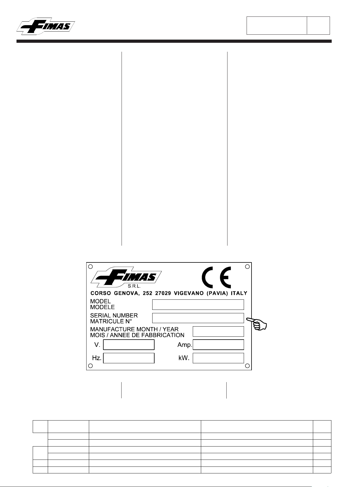
MATRICOLA NUMERO
. . . . . . . . . . . . . . . . . . . . . . . . . . . . . . . . . . . . .
. . . . . . . . . . . . . . . . . . . . . . . . . . . . . . . . . . . . .
FASI - Hz - VOLTS
. . . . . . . . . . . . . . . . . . . . . . . . . . . . . . . . . . . . .
DATA FABBRICAZIONE
CATALOGO NUMERO
104.013.1109
2~ 50/60Hz 220V
C.so Genova, 252 - 27029 VIGEVANO (PAVIA) - ITALY
Mod. 104.41-1109
MANUALE D'USO E MANUTENZIONE
USE AND MAINTENANCE INSTRUCTION
MANUEL D'UTILISATION ET D'ENTRETIEN
VERWENDUNGS-UND WARTUNGSBETRIEBSANLEITUNG
MANUAL DE USO Y MANTENIMENTO
SERIAL NUMBER
NUMERO MATRICULE
ARTIKEL NUMMER
NUMERO MATRICULA
CATALOGUE NUMBER
CATALOGUE NUMERO
KATALOG NUMMER
CATALOGO NUMERO
PHASES - Hz - VOLTS
PHASES - Hz - VOLTS
PHASEN - Hz - VOLTS
MANUFACTORING DATE
DATE FABRICATION
HERSTELLUNGSDATUM
FECHA DE FABRICACION
FASES - Hz - VOLTS
DOCUMENTO DI PROPRIETA' DELLA FIMAS s.r.l. RIPRODUZIONE VIETATA A TERMINI DI LEGGE - DOCUMENT OF FIMAS s.r.l. PROPERTY, REPRODUCTION FORBIDDEN AS TO LAW TERMS
n°
00100.204.0195 di 2
Pagina N°
DOCUMENTO DI PROPRIETA' DELLA FIMAS s.r.l. RIPRODUZIONE VIETATA A TERMINI DI LEGGE - DOCUMENT OF FIMAS s.r.l. PROPERTY, REPRODUCTION FORBIDDEN AS TO LAW TERMS
Pos. Codice
Code Descrizione Description Q.tà
11.232.46.007 Cilindro Ø 63 x 250 D.E. Cylinder Ø 63 x 250 D.E. 2
1.245.46.004-01 Serie standard guarnizioni Kit of gasket -
245.600.120 Lubrificatore Ø 3/8" Lubrificator Ø 3/8" 1
45.600.120-03 Serie standard Kit of spares -
3 45.600.140 Manometro Ø 1/8" Pressure gauge Ø 1/8" 1
4 15.500.400 Tubo di nylon 10 x 8 azzurro L=mt. Blue nylon tube 10 x 8 L=mt. -
)
ISTRUZIONI DI RICEVIMENTO E ASSISTENZA TECNICA
RECEIPT AND TECHNICAL ASSISTANCE INSTRUCTIONS
INSTRUCTIONS DE RECEPTION ET ASSISTANCE TECHNIQUE
1
(fig.2)
RICEVIMENTO
Al ricevimento della macchina controllare che l'imbal-
laggio sia integro,la fornitura corrisponda alle specifiche
dell'ordine e non vi siano danni;(in caso di danni o pez-
zi mancanti informare immediatamente ed in modo
dettagliato lo Spedizioniere e la FIMAS s.r.l.).
Il MANUALE,i CATALOGHI o i DISEGNI illustranti le
macchine FIMAS si intendono per l'impiego della mac-
china e non sono necessariamente precisi in ogni det-
taglio tecnico,quindi anche le dimensioni indicate non
sono vincolanti e possono essere modificate in qualsia-
si momento senza alcun preavviso.
I disegni e qualsiasi altra informazione contenuti in
questo MANUALE sono di proprietà della FIMAS
s.r.l. che se ne riserva tutti i diritti e non possono
essere messi a disposizione di terzi.
La FIMAS s.r.l. (Di seguito chiamata solo FIMAS per
semplificazione) si riserva di modificare una o più ca-
ratteristiche delle macchine senza alcun preavviso e
senza l'obbligo di fornire tali modifiche sulle macchine
già vendute alla data della modifica. La FIMAS rico-
nosce la garanzia sulle proprie macchine a condizio-
ne che tutti gli interventi di assistenza e di manuten-
zione siano effettuati dal proprio SERVIZIO DI ASSI-
STENZA TECNICA.
LA FIMAS NON E' RESPONSABILE IN CASO
DI MANOMISSIONE O MODIFICHE DELLA MAC-
CHINA.
ASSISTENZA TECNICA
Per qualsiasi informazione tecnica o di assistenza
rivolgersi all'ufficio ASSISTENZA TECNICA FIMAS
od all'AGENTE FIMAS DI ZONA citando sempre
il N° di matricola (fig.1).
RECEIPT
On receipt of the machine check if the package is
complete,the supply is in conformity with the order
specification and there is no damage; (in case of
damage or missed parts please inform immediately
and in detail both the forwarding agent and FIMAS
s.r.l.). The MANUAL, the LEAFLETS or the
DRAWINGS on which the FIMAS machines are
illustrated, are for the use of the machine and
they are not necessarily precise in each technical
detail, therefore also the indicated dimensions are
not binding and can be modified at any time and
without notice. The drawings and all other
information included in this MANUAL are the
property of FIMAS s.r.l. and cannot be placed at
third party disposal. FIMAS s.r.l. (hereinafter
called simply FIMAS) has the right to modify
one or more features of the machine without any
notice and is not obliged to fit the machines
already sold at the modification date with such
changes. FIMAS acknowledge the guarantee on
the machines of his production on condition that all
techincal and maintenance service are being made
by his TECHNICAL ASSISTANCE SERVICE.
FIMAS IS NOT RESPONSIBLE IN CASE OF
MACHINE THAT HAS BEEN TAMPERED WITH
OR MODIFIED.
TECHNICAL ASSISTANCE
For any technical or assistance information apply to
the FIMAS TECHNICAL ASSISTANCE office or to
the FIMAS AREA AGENT mentioning always the
machine serial N° (fig.1).
RECEPTION
A la réception de la machine contrôler que; l'emballage
soit entier,que la fourniture corresponde à la commande
et qu'il n'y a pas de dommages; (en cas de dommages
ou de pièces manquantes, informer immédiatament et
en détail le transitaire et FIMAS s.r.l.). Le MANUEL,
les CATALOGUES ou les DESSEINS rélatifs aux
machines FIMAS s'entendent pour l'emploi de la
machine et ne sont pas nécessariement précis
dans tout détail technique, donc aussi les dimensions
indiqués ne sont pas d'engagement et peuvent être
modifiées à n'importe quel moment sans aucun préavis.
Le desseins et tout autre renseignement contenus dans
ce MANUEL sont de propriété de FIMAS s.r.l. qui
se réserve tous les droits et ne peuvent pas être mis
à disposition de tiers. FIMAS s.r.l. (ci-dessous
appelée seulement FIMAS pour simplifier) se réserve
de modifier une ou plus charactéristiques des machines
sans aucun préavis et sans l'obligation de fournir ces
modifications sur les machines déjà vendues à la date
de la modification. FIMAS reconnaît la garantie sur ses
machines à condition que toute intervention
d'assistance et d'entretien soient effectuées par son
SERVICE D'ASSISTANCE TECHNIQUE.
FIMAS N'EST PAS RESPONSABLE EN CAS
D'EFFRACTION OU MODIFICATIONS DE LA
MACHINE.
ASSISTANCE TECHNIQUE
Pour tout renseignement technique ou d'assistance
s'addresser au SERVICE TECHNIQUE FIMAS ou à
l'AGENT FIMAS en indiquant toujours le numéro de
la machine (fig.1).
(fig.1)
Per ordinare pezzi di ricambio indicare sempre
il numero di codice degli stessi (fig.2) indicati ne-
gli elenchi dei ricambi del MANUALE.
For spare parts orders please state always the code
n° (fig.2) indicated on the spare parts list of the
MANUAL
Pour commander des pièces détachées,indiquer
toujours le numéro de référence des mêmes (fig.2)
indiqués dans le MANUEL.
n°
00100.204.0195 di 2
Pagina N°
DOCUMENTO DI PROPRIETA' DELLA FIMAS s.r.l. RIPRODUZIONE VIETATA A TERMINI DI LEGGE - DOCUMENT OF FIMAS s.r.l. PROPERTY, REPRODUCTION FORBIDDEN AS TO LAW TERMS
Pos. Codice
Code Descrizione Description Q.tà
11.232.46.007 Cilindro Ø 63 x 250 D.E. Cylinder Ø 63 x 250 D.E. 2
1.245.46.004-01 Serie standard guarnizioni Kit of gasket -
245.600.120 Lubrificatore Ø 3/8" Lubrificator Ø 3/8" 1
45.600.120-03 Serie standard Kit of spares -
3 45.600.140 Manometro Ø 1/8" Pressure gauge Ø 1/8" 1
4 15.500.400 Tubo di nylon 10 x 8 azzurro L=mt. Blue nylon tube 10 x 8 L=mt. -
)
2
EMPFANGSANWEISUNGEN UND TECHNISCHEN KUNDENDIENST
INSTRUCCIONES PARA LA RECEPCION Y LA ASISTENCIA TECNICA
RECEPCION
Al recibir la máquina controlar que el embalaje
esté integro, el suministro concorde con lo pedido
y que no hayan daños; (en caso de daños o falta de
piezas informar de inmediato y en detalle al
transportista y a FIMAS s.r.l.). El MANUAL, los
CATALOGOS o los DISEÑOS que muestran las
máquinas FIMAS son para el empleo de la máquina y
no son necesariamente precisos en cada detalle
técnico, por lo tanto las dimensiones indicadas
no son vinculantes y pueden ser modificadas en
cualquier momento sin aviso previo. Los diseños y
cualquier otra información incluida en este MANUAL
son propiedad de FIMAS s.r.l. con derechos
reservados y no pueden ser puestos a disposición de
terceros. FIMAS s.r.l. (que a continuación
indicamos solo como FIMAS para simplificación)
se reserva el derecho de modificar una o más
caracteristicas de las máquinas sin aviso previo y sin
obligación de aplicar tales variaciones a las
máquinas ya vendidas en la fecha de la modificación.
FIMAS reconoce la garantia de sus máquinas a
condición que todas las intervenciones de asistencia y
mantenimiento sean hechos por el propio SERVICIO
DE ASISTENCIA TECNICA.
FIMAS NO ES RESPONSABLE EN CASO
DE MANUMISIONES O MODIFICACIONES
DE LA MAQUINA.
ASISTENCIA TECNICA
Para cualquier información tecnica o asistencia llamar
al departamento ASISTENCIA TECNICA FIMAS o al
AGENTE FIMAS DE ZONA mencionando siempre el
N° de matricula (fig.1) de la máquina.
EMPFANG
Bei Empfang der Maschine prüfen Sie daß: die
Verpackung unversehrt ist, die Lieferung der
Bestellung entspricht und es keine Schaden gibt;
(im Fall von Schaden oder fehlenden Teile sofort
den Spediteur und die FIMAS s.r.l. informieren). Die
Betriebsanleitung, die Prospekte und die Zeichnungen
verstehen sich zur Maschineverwendung und sind
nicht genau in jeder technischen Einzelheit, deshalb
auch die angegbenen.
Ausmaße nicht verbindlich sind und können fristlose
Entlassung verändert werden. Die Zeichnungen und
jede in dieser Betriebsanleitung enthaltenen Auskunft
sind Eigentum der FIMAS s.r.l., die für sich alle
Rechten belegt und können zur Verfügung der
dritten Personen nicht stehen.
Die FIMAS s.r.l. (hier in der Folge nur FIMAS zur
Vereinfachung gennant) belegt für sich eine oder mehr
Eigenschaften der Maschinen fristlose Entlassung zu
ändern ohne Verpflichtung diese Aenderungen an
die schon gelieferten Maschinen zu bringen.
Die FIMAS erkennt die Garantie auf ihren Maschinen,
unter der Bedengung daß jedes Kundendienst-und
Wartungseingreifen von dem eigenen
TECHNISCHEN KUNDENDINST ausgeführt wird.
DIE FIMAS IST NICHT FUER ERBRECHEN
ODER AENDERUNGEN DER MASCHINE
VERANTWORTLICH.
TECHNISCHER KUNDENDIENST
Für jede technische Auskunft an die FIMAS
TECHNISCHEN KUNENDIENST oder an den
FIMAS Vertreter sich wenden, immer bei Mitteilung
der Maschinenummer (Bild 1).
Zur Bestellung der Ersatzteile immer die
Referenznummer der selben (Bild 2) angeben, die
in der Betriebsanleitung zu finden sind.
Para pedidos de repuestos indicar siempre el N° de
codigo de los mismos (fig.2) indicados en el elenco
de los repuestos del MANUAL.
(fig.2)
(fig.1)

n° 1
10100.104.1203 di 1
Pagina N°
RIPRODUZIONE VIETATA A TERMINI DI LEGGE - REPRODUCTION FORBIDDEN AS TO LAW TERMS
DIMENSIONI,CONNESSIONI,CONSUMI,PESI
DIMENSIONS,CONNECTIONS,CONSUMPTION,WEIGHT
DIMENSIONS,CONNECTIONS,CONSOMMATIONS,POIDS
AUSMASSEN,ANSCHLUBE,VERBRAUCHE,GEWICHTE
DIMENSIONES,CONEXIONES,CONSUMOS,PESOS
DIE ANGEGEBENENWERTEN BEZIEHEN SICH AUF DIE
MASCHINE OHNE ZUBEHÖREN. DIE VERBRAUCHE
SIND BEZÜGLICH EINES MITTELARBEITSZYKLUS UND
KÖNNEN AENDERUNGEN GEMÄSS DES EINGEFÜHRTES
ZYKLUS ERFAHREN.
LOS VALORES INDICADOS SE REFIEREN A LA
MAQUINA SIN ACCESORIOS.
LOS CONSUMOS SON RELATIVOS A UN CICLO
MEDIO DE TRABAJO Y PUEDEN VARIAR SEGUN
EL CICLO ADOPTADO.
I VALORI RIPORTATI SI RIFERISCONO ALLA MAC-
CHINA SENZA ACCESSORI.
I CONSUMI SONO RELATIVI AD UN CICLO MEDIO DI
LAVORO E POSSONO SUBIRE VARIAZIONI IN FUN-
ZIONE DEL CICLO ADOTTATO.
THE QUOTED VALUES REFER TO THE MACHINE
WITHOUT ACCESSORIES.
THE CONSUMPTIONS CONCERN A MEDIUM WORK
CYCLE AND CAN CHANGE ACCORDING TO THE
ADOPTED CYCLE.
LES VALEURS INDIQUEES SE REFERENT A LA
MACHINE SANS ACCESSOIRES.
LES CONSOMMATIONS SONT RELATIVES A UN CYCLE
MOYEN DE TRAVAIL ET PEUVENT SUBRIR DES
MODIFICATIONS PAR RAPPORT AU CYCLE ADOPTE.
41-1109
n°
di 2
Pagina N°
20200.104.1203
RIPRODUZIONE VIETATA A TERMINI DI LEGGE - REPRODUCTION FORBIDDEN AS TO LAW TERMS
1
FONTI DI ENERGIA E CONNESSIONI
SOURCES OF ENERGY AND CONNECTIONS
SOURCES D'ÉNERGIE ET CONNECTIONS
ENERGIE QUELLE UND ANSCHLUESSE
FUENTES DE ENERGIA Y CONEXIONES
Per il funzionamento della macchina sono necessarie
le seguenti fonti di energia:
ARIA COMPRESSA
È necessaria una pressione minima di 6 Ate (85 Psi).
Installare apparecchi deumidificatori e disoleatori
all'uscita del compressore.
ELETTRICITA'
La macchina è prevista per essere alimentata alla tensione
e frequenza richiesta (vedi targhetta alimentazione).
Il risultato e la costanza della qualità di stiratura
dipendono in modo determinante dalla costanza e qualità
dei fluidi usati per cui è importante che le macchine
produttrici degli stessi siano dimensionate ed installate in
modo corretto.
I materiali utilizzati devono necessariamente avere le
caratteristiche come di seguito indicate (Si fornisce, a
richiesta, Kits per le connessioni).
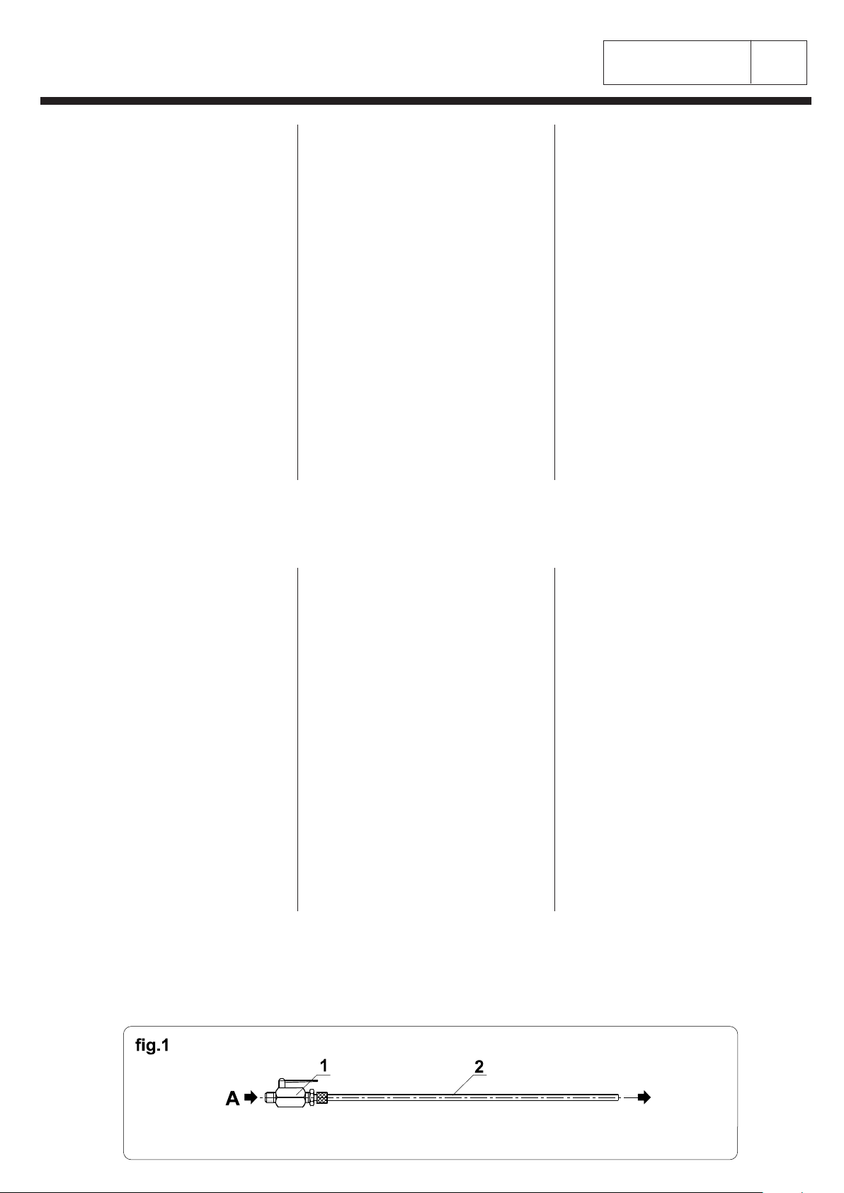
CARATTERISTICHE MATERIALI E CONNESSIONI (fig.1)
A - ARIA COMPRESSA
1 - Valvola a sfera pressione d'esercizio 13 Ate (182 Psi).
2 - Tubo in RILSAN pressione d'esercizio 40 Ate (580 Psi).
B - ENERGIA ELETTRICA
- Collegare la macchina secondo NORME C.E.I. 64/8.
- La protezione del conduttore d'alimentazione deve
essere secondo le NORME EN 60204.
- Collegare il nodo equipotenziale.
For the machine running they are needed the following
sources of energy:
COMPRESSED AIR
It is necessary a 6 Atm (85 Psi) minimum pressure.
Install at the compressor outlet dehumidifiers and
equipment to separate the oil.
ELECTRICITY
The machine is foreseen to be feed with the required
voltage and frequency (see feed plate).
The result and the constancy of the ironing quality
depend mainly on the constancy and quality of the used
fluids therefore it is important that the machines which
produces them are measured and installed in a correct
manner.
The used materials must have the characteristics as
follows (It is supplies, under request, connections kits).
FEATURES OF MATERIALS AND CONNECTIONS (fig.1)
A - COMPRESSED AIR
1 - Ball valve, working pressure 13 Atm (182 Psi).
2 - RILSAN pipe, working pressure 40 Atm (580 Psi).
B - ELECTRIC ENERGY
- Connect the machine as per C.E.I. 64/8 STANDARD.
- The wire coating must be as per EN 60204 STANDARD.
- Connect the unipotential node.
Pour le fonctionnement de la machine sont nécessaires
les sources d'énergie suivantes:
AIR COMPRIME
Il est nécessaire une pression minimum de 6 Ate (85 Psi).
Installer des appareils déshumidificateurs et qui
extrairent l'huile à la sortie du compresseur.
ELECTRICITE
La machine est prévue pour être alimentée à la tension
et fréquence demandée (voir plaquette alimentation).
Le résultat et la constance de la qualité de repassage
dépendent de façon déterminante de la constance et de
la qualité des fluides utilisés, donc il est important que
les machines produisant les mêmes soient dimensionnées
et installées de façon correcte.
Les matériaux utilisés doivent nécessariement avoir les
charactéristiques indiquées comme il suit (On peut
fournir sur demande des ensembles complets pour les
branchements).
CHARACTERISTIQUES MATERIAUX ET CONNECTIONS
(fig.1)
A - AIR COMPRIME
1 - Valve à bille pression vapeur 13 Ate (182 Psi).
2 - Tuyau en RILSAN pression vapeur 40 Ate (580 Psi).
B - ENERGIE ELECTRIQUE
- Brancher la machine suivant les REGLEMENTATIONS
C.E.I. 64/8.
- La protection du conducteur d'alimentation doit être
sélon les REGLEMENTATION EN 60204.
- Brancher le noeud équipotentiel.
Zum Betrieb der Maschine sind die folgenden Kraftquellen
notwendig:
PRESSLUFT
Ein minimal Druck von 6 Ate (85 Psi) ist notwendig.
Entfeuchtungs-und Entölungsvorrichtungen bei
Kompressor Austritt installieren.
ELEKTRIZITAET
Die Maschine ist zum Anschluss an die benötigte Spannung
und Frequenz vorgesehen (siehe Spannungsschild).
Das Ergebnis und die Beständigkeit der Bügelqualität
hängen auf entscheidende Weise von der Beständigkeit
und Qualität der verwendeten Flüßigkeiten, deshalb ist es
wichtig daß die Herstellermaschinender selben auf
richtige Weise installiert werden.
Die verwendeten Materialien sollen unbedingt die
Eigenschaften wie folgt haben (Bei Anfrage kann alles
Notwendiges für die Anschlüsse liefern).
MATERIALEN EIGENSCHAFTEN UND ANSCHLUESSE
(Bild 1)
A - PRESSLUFT
1 - Kugelventil Betriebsdruck 13 Ate (182 Psi).
2 - Schlauch aus RILSAN Betriebsdruck 40 Ate (580 Psi).
B - ELEKTRISCHE ENERGIE
- Die Maschine gemaess C.E.I. 64/8 Vorschriften
anschliessen.
- Die Schutz des Speisungsleiter soll gemaess der
EN 60204 Vorschriften sein.
- Gleichpotentiellen Knoten anschliessen.
Para el funcionamento de la máquina son necesarias
las siguientes fuentes de energia:
AIRE COMPRIMIDO
Se necesita una presión minima de 6 Ate (85 Psi).
Instalar deshumidificadores y desaceitadores a la
salida del compresor.
ELECTRICIDAD
La máquina está prevista para ser alimentada a la tensión
y frecuencia requeridas (ver tarjeta alimentación).
El resultado y la constancia de la calidad de
planchado dependen en modo determinante de la
constancia y calidad de los fluidos usados, por esto es
importante que las máquinas que producen los mismos
sean dimensionadas e instaladas en modo correcto.
Los materiales utilizados deben tener necesariamente las
caracteristicas indicadas de seguido (Se suministra, bajo
pedido, Kits para conexiones).
CARACTERISTICAS DE LOS MATERIALES Y
CONEXIONES (fig.1)
A - AIRE COMPRIMIDO
1 - Válvula esférica, presión de servicio 13 Ate (182 Psi).
2 - Tubo de RILSAN presión de servicio 40 Ate (580 Psi).
B - ENERGIA ELECTRICA
- Conectar la máquina según NORMAS C.E.I. 64/8.
- La protección del conductor de alimentación debe ser
según las NORMAS EN 60204.
- Conectar el nudo equipotencial.

n°
di 2
Pagina N°
20200.104.1203
RIPRODUZIONE VIETATA A TERMINI DI LEGGE - REPRODUCTION FORBIDDEN AS TO LAW TERMS
2
CONNESSIONI
CONNECTIONS
CONNECTIONS
ANSCHLUESSE
CONEXIONES
N.B.: Las operaciones de conexión deben ser realizadas
por tecnicos especializados.
Los esquemas de conexiones pueden ser variados en
función de los accesorios requeridos sobre la máquina.
N.B.: Le operazioni di connessione devono essere realizzate
da tecnici specializzati.
Gli schemi di connessione possono subire variazioni in
funzione degli accessori richiesti sulla macchina.
N.B.: The connection work must be done by qualified
technicians.
The diagrams of connection can be changed according
to the accessories applied on the machine.
N.B.: Les opérations de branchement doivent être effectuées
par des techniciens spécialisés.
Les schémas de connection peuvent subir des modifications
par rapport aux accessoires demandés sur la machine.
Prima di effettuare il collegamento della macchina
agli impianti di alimentazione provvedere allo SPURGO
delle tubazioni.
Gli impianti che trasportano i fluidi possono essere
installati a terra (fig.1) od a soffitto (fig.2).
Before connecting the machine to the feeding
plants DRAIN the pipelines.
The pipes which convey the fluids can be installed
on ground (fig.1) or at ceiling (fig.2).
Antes de conectar la máquina a las instalaciones de
alimentación proveer al DRENAJE de las tuberias.
Las instalaciones que transportan los fluidos
pueden ser instalados a suelo (fig.1) o a techo
(fig.2).
Avant d'effectuer le branchement de la machine
aux installations d'alimentation effectuer le
NETTOYAGE des conduites.
Les installations qui transportent les fluides peuvent
être installées à terre (fig.1) ou au plafond (fig.2).
Vor dem Anschluss der Maschine an die
Speisungsanlagen mit der REINIGUNG der
Rohrleitungen vorgehen.
Die Anlagen, die Fluessigkeiten transportieren,
koennen am Boden (Bild 1) oder am Plafond (Bild 2)
installiert werden.
BEMERKUNG: Die Anschlussverfahren sollen von
Fachtechniker durchgefuehrt werden.
Die Schaltplaene koennen Aenderungen gemaess der
angefragten Zubehoeren der Maschinen erfahren.

n° 1
di 1
Pagina N°
30100.104.1203
RIPRODUZIONE VIETATA A TERMINI DI LEGGE - REPRODUCTION FORBIDDEN AS TO LAW TERMS
DISPOSITIVI DI SICUREZZA
SAFETY DEVICES
DISPOSITIFS DE SÉCURITÉ
SICHERHEITSVORRICHTUNGEN
DISPOSITIVOS DE SEGURIDAD
SCHUETZE
Die Maschine ist mit festen Schütze (EN 292/2) ausgestattet.
GLEICHPOTENTIELLER KNOTEN (Bild 1 Stellung 2)
Die Klemme des Schutzkreises gemäss der Vorschriften
EN 60204-1 auschliessen.
BEMERKUNG: Trotz der obengenannten Vorrichtungen und
Vorsichten, empfehlen wir noch:
-Wartungen durchführen nur wenn alle Energiequellen
ausgeschlossen sind.
PROTECCIONES
La máquina se entrega con protecciones fijas (EN 292/2).
NUDO EQUIPOTENCIAL (fig.1 pos.2)
Conectar el borne del circuito de protección a NORMA
EN 60204-1.
N.B.: No obstante los dispositivos y las precauciones
susodichas se recomienda también de:
-No efectuar intervenciones de mantenimiento si no fueron
antes excluidas todas las fuentes de energia.
RIPARI
La macchina è provvista di ripari fissi (EN 292/2).
NODO EQUIPOTENZIALE (fig.1 pos.2)
Collegare il morsetto del circuito di protezione a NORMA
EN 60204-1.
N.B.: Nonostante i dispositivi e le precauzioni sopra
elencate si raccomanda ancora di:
-Non effettuare interventi di manutenzione se non dopo
aver escluso tutte le fonti di energia.
GUARDS
The machine is supplied with fixed guards (EN 292/2).
UNIPOTENTIAL NODE (fig.1 pos.2)
Connect the terminal of the protection circuit as per
STANDARD EN 60204-1.
N.B.: Further to the above mentioned devices and precautions
it is recommended to:
-Not carry out any maintenance before having excluded
all energy sources.
PROTECTIONS
La machine est pourvue avec des protections fixes (EN 292/2).
NOEUD EQUIPOTENTIEL (fig.1 pos.2)
Brancher la borne du circuit de protection aux TERMES
du EN 60204-1.
N.B.: Malgré les dispositifs et les précautions ci-dessus
indiqués nous recommandons encore de:
-Effectuer des entretiens seulement après avoir débranché
chaque source d'énergie.
HAUPTSCHALTER (Bild 1 Stellung 1)
Der Maschine Hauptschalter erlaubt die Unterbrechung der
elektrischen Speisung von Stellung "I" bis Stellung "O" (Bild 2).
THERMISCHE SICHERUNG (Bild 1 Stellung 3)
Sie tritt in Betrieb ein, wenn die Temperatur aus zufaelligen
Verursachen 120°C uebersteigt. Im Fall von Eingriff kann
die Sicherung nicht wiedereingeschaltest werden, deshalb
nachdem man die Ursache des Schadens festgestellt hat,
muss sie ersetzt werden.
INTERRUPTOR GENERAL (fig.1 pos.1)
Posicionando el interruptor general de la máquina de la pos."I"
a la pos."O" se interrumpe la alimentación eléctrica (fig.2).
FUSIBLE TERMICO (fig.1 pos.3)
Interviene cuando la temperatura, por causas accidentales, su-
pera 120°C. El fusible no puede ser reactivado, por lo tanto
tras haber constatado el tipo de avería deberá ser
reemplazado.
INTERRUTTORE GENERALE (fig.1 pos.1)
L'interruttore generale di macchina consente, dalla pos."I" alla
pos."O", l'interruzione dell'alimentazione elettrica (fig.2).
FUSIBILE TERMICO (fig.1 pos.3)
Interviene quando la temperatura, per cause accidentali,
supera 120°C. Nel caso di intervento il fusibile non è
riarmabile, quindi dopo avere accertato la natura del
guasto dovrà essere sostituito.
INTERRUPTEUR GENERAL (fig.1 pos.1)
L'interrupteur général de machine permet de la pos."I" à la
pos."O", l'interruption de l'alimentation électrique (fig. 2).
FUSIBLE THERMIQUE (fig.1 pos.3)
Il entre en fonction quand la température, pour des causes
accidentelles, dépasse 120°C. Dans le cas d'intervention le
fusible ne peut pas être rétabli, donc après avoir vérifié la
nature de la panne il devra être remplacé.
GENERAL SWITCH (fig.1 pos.1)
The machine general switch is permitting the interruption
of electrical supply from pos."I" to pos."O" (fig.2).
THERMIC FUSE (fig.1 pos.3)
It is working when, due to accidental causes, it is
exceeding 120°C. In case of working the fuse is not
fitted out again, therefore after having settled the cause
of the trouble it has to be replaced.
La máquina se entrega con varios DISPOSITIVOS
DE SEGURIDAD reproducidas por colocación y
funcionamento. El personal que usa la máquina debe
conocer los mismos.
Die Maschine ist mit verschiedenen Sicherheits-
vorrichtungen ausgerüstet.
Diese sollen zur Kenntnis des Maschinepersonals
sein.
La machine est pourvue avec différents DISPOSITIFS
DE SECURITE représentés comme emplacement et
fonctionnement. Ceux-ci doîvent être connus par le
personnel préposé à la machine.
The machine is equipped with different SAFETY
DEVICES represented as disposition and functioning.
Machine operators must be acquainted with these
devices.
La macchina è dotata di vari DISPOSITIVI DI SICUREZZA
raffigurati come dislocazione e funzionamento. Questi
devono essere a conoscenza del personale addetto alla
macchina.
n° 1
di 1
Pagina N°
40200.104.1203
RIPRODUZIONE VIETATA A TERMINI DI LEGGE - REPRODUCTION FORBIDDEN AS TO LAW TERMS
SUGGERIMENTI - CONTROLLI
SUGGESTIONS - CHECKS
SUGGESTIONS - CONTRÔLES
VORSCHLAEGE - KONTROLLE
CONSEJOS - CONTROLES
SUGGERIMENTI
Si raccomanda di leggere attentamente quanto segue e
di attenersi scrupolosamente alle istruzioni contenute
onde evitare inconvenienti o incidenti.
Solo una persona addestrata e che conosce perfettamente
la macchina ed i dispositivi di sicurezza può metterla in
funzione assicurandosi che non vi siano altre persone
nelle immediate vicinanze e che non vi siano grasso, olio
od oggetti che possano creare impedimenti nella zona di
lavoro.
Altrettanto dicasi per gli interventi di manutenzione che
devono essere svolti solo da personale addestrato,
dopo avere escluso tutte le fonti di energia.
Pertanto qualora la persona esposta rilevi avarie o
pericoli dovrà informare immediatamente il personale di
manutenzione od il suo diretto superiore che a sua volta
provvederà a fare intervenire il personale sopraddetto.
SUGGESTIONS
It is recommended to read carefully the following and to
follow with scrupulous care the included instructions to
avoid problems or injuries.
Only a trained person who knows perfectly the machine
and its safety devices can start it making sure there is
no other person near the machine and that there is no
grease, oil or other things that may cause obstacles in
the working area.
Same care must be taken for the maintenance services
which must be done only by trained persons, after
having excluded all energy sources.
Therefore in case that the operator notes failures or
dangers, they must inform immediately the persons in
charge of the maintenance or his immediate superior
who will ask the proper persons to intervene.
SUGGESTIONS
Nous vous recommandons de lire soigneusement ce qui
suit et de suivre scrupuleusement les instructions contenues à
fin d'éviter des inconvénients ou des accidents.
Seulement une personne entraînée et qui connaît
parfaitement la machine et les dispositifs de sécurité
peut la mettre en fonction et s'assurer qu'il n'y a pas
d'autres personnes dans le voisinage immédiat et qu'il
n'y a pas de graisse, huile ou objets qui puissent causer
des obstacles au travail.
C'est la même chose pour les interventions d'entretien
qui ne doivent être effectuées que par du personnel
entraîné, après avoir débranché toute source d'énergie.
Donc dans le cas où l'opérateur remarque des avaries
ou des dangers devra informer toute de suite le personnel
d'entretien ou son chef directeur qui à son tour faira
intervenir le personnel susdit.
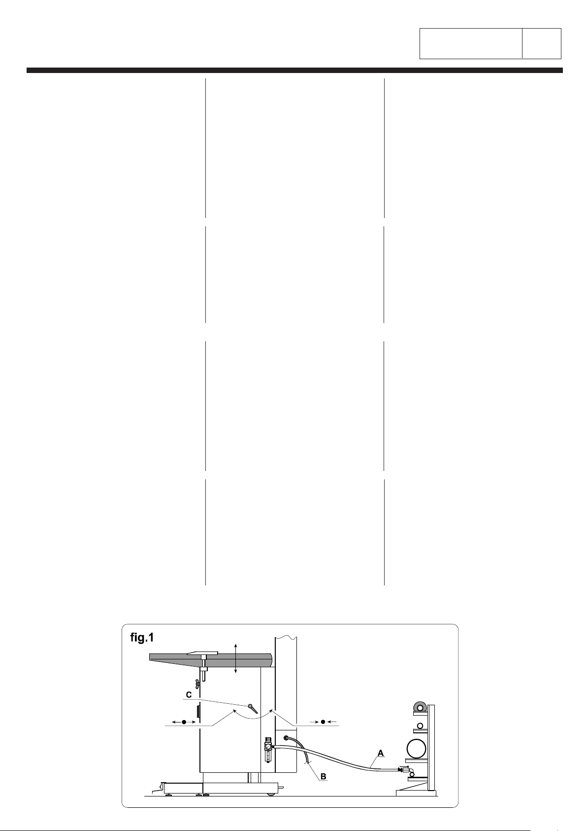
CONTROLLI PRIMA DELL'AVVIAMENTO
CONTROLLARE (fig.1):
A - ARIA COMPRESSA
Esatta connessione.
B - ENERGIA ELETTRICA
Esatta connessione, tensione e messa a terra.
REGOLAZIONE DEL PIANO DI LAVORO
Agire sulla leva "c" per sbloccare la colonna. Regolare
l'altezza del piano di lavoro e ribloccare la colonna.
RIPARI DI PROTEZIONE
Accertarsi che siano debitamente fissati al telaio della
macchina.
CHECKS BEFORE THE START
CHECK (fig.1):
A - COMPRESSED AIR
Proper connection.
B - ELECTRIC ENERGY
Proper connection, voltage and grounding.
ADJUSTMENT OF WORKING SURFACE
Act on lever "c" to release the column. Adjust the height
of the working surface and block the column again.
SAFETY SHIELDS
Be sure that they are properly fixed to the frame of
the machine.
CONTRÔLES AVANT LE DÉMARRAGE
VERIFIER (fig.1):
A - AIR COMPRIME
Exacte connection.
B - ENERGIE ELECTRIQUE
Exacte connection, tension et mise à la terre.
REGLAGE PLATEAU DE TRAVAIL
Agir sur le levier "c" pour débloquer la colonne. Régler la
hauteur du plateau de travail et rebloquer la colonne.
PROTECTIONS
S'assurer qu'elles soient fixées au chassis de la
machine.
CONSEJOS
Se aconseja leer con atención lo siguiente y seguir
escrupulosamente las instrucciones contenidas para
evitar inconvenientes o accidentes.
Solo una persona adiestrada y que conoce perfectamente
la máquina y los dispositivos de seguridad puede hacerla
funcionar asegurandose que no hayan otras personas
cerca de la máquina y que no haya grasa, aceite u otros
objetos que puedan estorbar la zona de trabajo.
Lo mismo vale para las intervenciones de mantenimiento
que deben ser hechas solo por personal adiestrado,
luego de haber excluido todas las fuentes de energia.
Por lo tanto en el caso que el operador note averías o
peligros deberá informar de inmediato el personal
encargado del mantenimiento o su directo superior, que
a su vez proveerá a hacer intervenir el personal susodicho.
CONTROLES ANTES DE LA PUESTA EN MARCHA
CONTROLAR (fig.1):
A - AIRE COMPRIMIDO
Correcta conexión.
B - ENERGIA ELECTRICA
Correcta conexión, tensión y puesta a tierra.
REGULACION DE LA FORMA
Obrar sobre la leva "c" para desbloquear la columna.
regular la altura de la forma y rebloquear la columna.
PROTECCIONES
Asegurarse que las mismas estén fijadas en el
modo correcto al chasis de la máquina.
VORSCHLAEGE
Wir empfehlen das folgendes mit Aufmerksamkeit zu lesen
und den enthaltenen Anweisungen genau zu folgen, um
Uebelstände oder Unfälle zu vermeiden.
Nur eine geübte Person, die die Maschine und die Sicherheits-
vorrichtungen perfekt kennt, kann sie in Betrieb setzen, bei der
Sicherheit daß es keine andere Person in der Umgebung gibt
und daß es kein Fett, Oel oder Dinge gibt, die Hindernisse
im Arbeitsbereich verursachen können.
Gleichfalls für Wartungseingriffe die nur von autorisiertem
Personal ausgeführt werden sollen, nachdem alle
Energiequellen ausgeschlossen werden.
Deshalb wenn die ausgesetzte Person Schaden oder
Gefahre festgestellt, soll sie das Wartungspersonal oder
seinen Chef sofort informieren, der seinerseits das
obengenanntes Personal eingreifen lassen wird.
KONTROLLE VOR DER INBETRIEBSETZUNG
PRUFEN (Bild 1):
A - PRESSLUFT
Richtigen Anschluss.
B - ELEKTRISCHE ENERGIE
Richtigen Anschluss, Spannung und Erdschluss.
REGULIERUNG DER ARBEITSFLAECHE
Auf Hebel "c" einwirken zur Entblockung der Säule. Die
Höhe der Arbeitsfläche regulieren und die Säule
wiederblockieren.
SCHUETZE
Feststellen dass sie am Rahmen der Maschine gut
fixiert sind.

n° 1
di 1
Pagina N°
50100.104.1203
RIPRODUZIONE VIETATA A TERMINI DI LEGGE - REPRODUCTION FORBIDDEN AS TO LAW TERMS
COMANDI
Tutti i comandi sono identificati con segni grafici e le
funzioni che vengono da essi attivate sono spiegate
nella tabella che segue con riferimento allo schizzo
sottostante.
La pedaliera è esposta nelle due combinazioni disponibili.
COMANDI
CONTROLS
COMMANDES
STEUERUNGEN
MANDOS
CONTROLS
All controls are identified by graphic marks and the
functions activated by them are explained in the following
table referring to drawing below.
The foot-pedal unit is shawn in the two available
combinations.
COMMANDES
Toutes les commandes sont identifiées par des signaux
graphiques et les fonctions activées par eux mêmes sont
expliquées dans le tableau suivant avec référence aux
croquis indiqué au-dessous.
Le groupe pédale est exposé dans les deux combinaisons
disponibles.
STEUERUNGEN
Alle Steuerungen sind mit graphischen Zeichen identifiziert
und die von Ihnen in Betrieb gesetzten Funktionen werden
in den folgenden Tafel mit Bezug auf dem darunter
liegenden Skizze erklärt.
Die Fußpedaleinheit ist in den zwei verfügbaren
Kombinationen ausgestellt.
MANDOS
Todos los mandos están identificados con signos
gráficos y las funciones que los mismos activan estàn
explicadas en la tabla que sigue con referencia al
croquis que sigue.
POS. BESCHREIBUNG FUNKTION DESCRIPCION FUNCION
QS1 HAUPTSCHALTER Die Spannung ein oder
ausschaltet INTERRUPTOR
GENERAL Conecta o excluye la tension
SB1 SCHALTER
FLAECHE
HEIZUNG
O-ausgeschaltet
I-die elektrische Heizung der
Form auf den Tisch einschaltet
INTERRUPTOR
CALENTAMIENTO
FORMA
O-deactivado
I-conecta la resistencia electri-
ca de la forma de la mesa
SB2 SCHALTER
AERMELBUEGEL-
FORMEN HEIZUNG
O-ausgeschaltet
I-die elektrische Heizung der
Aermelbügelformen
INTERRUPTOR
CALENTAMIENTO
JANETTES
O-deactivado
I-conecta la resistencia
electrica de las janettes
SB3 FUßPEDAL
ABSAUGUNG Er steuert die Absaugung aus
der Arbeitsfläche PEDAL
ASPIRACION Manda la aspiracion de la
forma
SB4 FUßPEDAL
BLASEN
(Wenn anwesend)
Er steuert das Blasen aus der
Arbeitsfläche PEDAL SOPLADO
(Si existe) Manda el soplado de la forma
aHEBEL ZUR
ABSAUGUNG
REGULIERUNG
Reguliert die Stärke der
Absaugung der Form auf dem
Bügeltisch und der
Bügelformen
LEVA
REGULACION
ASPIRACION
Regula l'intensidad de
l'aspiracion de la forma sobre
la mesa ó de las janettes
b
HEBEL ZUR
BLASEN
REGULIERUNG
(Wenn anwesend)
Reguliert die Stärke des
Blasens der Form auf dem
Bügeltisch und der
Bügelformen
LEVA
REGULACION
SOPLADO
(Si existe)
Regula l'intensidad del
soplado de la forma sobre la
mesa ó de las janettes
POS. DESCRIZIONE FUNZIONE DESCRIPTION FUNCTION DESCRIPTION FONCTION
QS1 INTERRUTTORE
GENERALE Inserisce o esclude la tensione GENERAL
SWITCH It switches on or off the tension INTERRUPTEUR
GENERAL Branche ou débranche la
tension
SB1 INTERRUTTORE
RISCALDAMENTO
PIANO
O-disinserito
I-inserisce la resistenza
elettrica della forma sul tavolo
PLATE HEATING
SWITCH
O-switched off
I-switched on the electrical
heating element of the shape
on the table
INTERRUPTEUR
CHAUFFAGE
PLATEAU
O-débranché
I-branche la résistance
électrique de la forme sur la
table
SB2 INTERRUTTORE
RISCALDAMENTO
JEANNETTES
O-disinserito
I-inserisce le resistenze
elettriche delle jeannettes
SLEEVE FORMS
HEATING SWITCH
O-switched off
I-switched on the electrical
heating elements of the sleeve
forms
INTERRUPTEUR
CHAUFFAGE
JEANNETTES
O-débranché
I-branche les résistances
électriques des jeannettes
SB3 PEDALE
ASPIRAZIONE Comanda l'aspirazione dal
piano di lavoro FOOT-PEDAL
VACUUM It controls vacuum from the
working surface PEDALE
ASPIRATION Commande l'aspiration du
plateau de travail
SB4 PEDALE
SOFFIAGGIO
(Se presente)
Comanda il soffiaggio dal pia-
no di lavoro
FOOT-PEDAL
BLOWING
(If present)
It controls blowing from the
working surface
PEDALE
SOUFFLAGE
(Si present)
Commande le soufflage du
plateau de travail
aLEVA
REGOLAZIONE
ASPIRAZIONE
Regola l'intensità dell'a-
spirazione della forma sul
tavolo o delle jeannettes
LEVER FOR
VACUUM
ADJUSTMENT
It is adjusting the vacuum
intensity of the shape on table
or the sleeve forms
LEVIER REGLAGE
ASPIRATION Règle l'intensité de l'aspiration
du plateau ou des jeannettes
b
LEVA
REGOLAZIONE
SOFFIAGGIO
(Se presente)
Regola l'intensità del
soffiaggio della forma sul
tavolo o delle jeannettes
LEVER FOR
BLOWING
ADJUSTMENT
(If present)
It is adjusting the blowing
intensity of the shape on the
table or the sleeve forms
LEVIER REGLAGE
SOUFFLAGE
(Si present)
Règle l'intensité du soufflage
du plateau ou des jeannettes

n° 1
di 2
Pagina N°
50200.104.1203
RIPRODUZIONE VIETATA A TERMINI DI LEGGE - REPRODUCTION FORBIDDEN AS TO LAW TERMS
AVVIAMENTO DELLA MACCHINA (fig.1)
ARIA COMPRESSA
Aprire la valvola "A" e verificare la pressione di entrata a 6
Ate (85 Psi) altrimenti agire sul volantino del riduttore "FR". La
lettura della pressione si rileva sul manometro "H1".
ENERGIA ELETTRICA
Posizionare l'interruttore generale della macchina "QS1"
su "I".
USO DELLA MACCHINA (fig.1)
RISCALDAMENTO DEL PIANO DI LAVORO
Posizionare su "I" l'interruttore "SB1". Si accenderà la
spia luminosa incorporata.
RISCALDAMENTO DELLE JEANNETTES
Se la macchina è corredata di jeannettes riscaldate,
posizionare su "I" l'interruttore "SB2". Si accenderà la
spia luminosa incorporata.
ASPIRAZIONE
Premere il pedale "SB3" per il tempo desiderato.
SOFFIAGGIO (Se presente)
Premere il pedale "SB4" per il tempo desiderato.
REGOLAZIONE ASPIRAZIONE
Agire sulla leva "a" per regolare l'intensità dell'aspirazione
della forma sul tavolo o delle jeannettes (se incluse).
REGOLAZIONE SOFFIAGGIO (Se presente)
Agire sulla leva "b" per regolare l'intensità del soffiaggio
della forma sul tavolo o delle jeannettes (se incluse).
ARRESTO DELLA MACCHINA (fig.1)
1-Posizionare su "O" gli interruttori "SB1 - SB2". Si
spegneranno le spie luminose incorporate.
2-Posizionare l'interruttore generale della macchina "QS1"
su "O".
ARRESTO DI EMERGENZA DELLA MACCHINA (fig.1)
Posizionare l'interruttore generale della macchina "QS1"
su "O".
N.B.: In caso di arresto prolungato della macchina esclude-
re ogni fonte di energia.
MACHINE START (fig.1)
COMPRESSED AIR
Open valve "A" adjusting the inlet pressure at 6 Ate (85 Psi)
operating on handwheel of reducer "FR". The pressure
is indicated by the pressure gauge "H1".
ELECTRICAL POWER
Put the machine general switch "QS1" on "I".
USE OF THE MACHINE (fig.1)
HEATING OF THE WORKING SURFACE
Put on "I" the switch "SB1". It will light on the built-in
signal lamp.
HEATING OF SLEEVE FORMS
If the machine is including heated sleeve forms put on
"I" the switch "SB2". It will light on the built-in signal lamp.
VACUUM
Press foot-pedal "SB3" for the desired time.
BLOWING (If present)
Press foot-pedal "SB4" for the desired time.
VACUUM ADJUSTMENT
Operate on lever "a" to adjust the vacuum intensity of the
shape on the table or of the sleeve forms (if present).
BLOWING ADJUSTMENT (If present)
Operate on lever "b" to adjust the blowing intensity of the
shape on the table or of the sleeve forms (if present).
STOP OF THE MACHINE (fig.1)
1-Put on "O" the switch "SB1 - SB2". It will light off the
built-in signal lamp.
2-Put on "O" the general switch of the machine "QS1".
EMERGENCY STOP OF THE MACHINE (fig.1)
Put on "O" the general switch of the machine "QS1".
N.B.: In case of extended stop of the machine cut out
any the power.
AVVIAMENTO, USO ED ARRESTO DELLA MACCHINA
MACHINE START, USE AND STOP
DÉMARRAGE, UTILISATION ET ARRÊT DE LA MACHINE
DÉMARRAGE DE LA MACHINE (fig.1)
AIR COMPRIME
Ouvrir la valve "A" et vérifier la pression d'entrée à 6 Ate
(85 Psi) sinon agir sur le volant du réducteur "FR". La
lecture de la pression est rélévée sur le manomètre "H1".
ÉNERGIE ÉLECTRIQUE
Positionner l'interrupteur général de la machine "QS1"
sur "I".
UTILISATION DE LA MACHINE (fig.1)
CHAUFFAGE DU PLATEAU DE TRAVAIL
Positionner sur "I" l'interrupteur "SB1". La lampe témoin
incorporée s'allumera.
CHAUFFAGE DES JEANNETTES
Si la machine est équipée avec des jannettes chauffées,
positionner sur "I" l'interrupteur "SB2". La lampe témoin
incorporée s'allumera.
ASPIRATION
Appuyer sur la pédale "SB3" pour le temps désiré.
SOUFFLAGE (Si present)
Appuyer sur la pédale "SB4" pour le temps désiré.
REGLAGE ASPIRATION
Agir sur le levier "a" pour régler l'intensité de l'aspiration
du plateau sur la table ou des jeannettes (si present).
REGLAGE SOUFFLAGE (Si present)
Agir sur le levier "b" pour régler l'intensité du soufflage
du plateau sur la table ou des jeannettes (si present).
ARRET DE LA MACHINE (fig.1)
1-Positionner sur "O" les interrupteurs "SB1 - SB2". La
lampe témoin incorporée s'éteignera.
2-Positionner l'interrupteur général de la machine "QS1"
sur "O".
ARRET D'URGENCE DE LA MACHINE (fig.1)
Positionner l'interrupteur général de la machine "QS1"
sur "O".
N.B.: Dans le cas d'arrêt prolongé de la machine,
débrancher toute source d'énergie.

n° 2
di 2
Pagina N°
50200.104.1203
RIPRODUZIONE VIETATA A TERMINI DI LEGGE - REPRODUCTION FORBIDDEN AS TO LAW TERMS
INBETRIEBSETZUNG, VERWENDUNG UND AUFHALTEN DER MASCHINE
PUESTA EN MARCHA, USO Y PARO DE LA MÁQUINA
INEBTRIEBSETZUNG DER MASCHINE (Bild 1)
PRESSLUFT
Das Ventil "A" oeffnen und den Eintrittsdruck von 6 Ate
(85 Psi) pruefen oder auf Steuerrad des Verminderers "FR"
einwirken. Der Druck wird aus Manometer "H1" angegeben.
ELEKTRISCHE ENERGIE
Den Hauptschalter der Maschine "QS1" auf "I" stellen.
VERWENDUNG DER MASCHINE (Bild 1)
HEIZUNG DER ARBEITSFSFLAECHE
Den Schalter "SB1" auf "I" stellen. Die eingebaute
Kontrolleuchte wird einschalten.
HEIZUNG DER AERMELBUEGELFORMEN
Wenn die Maschine mit beheizten Armbuegelformen
ausgestattet ist, Schalter "SB2" auch auf "I" stellen. Die
eingebaute Kontrolleuchte wird einschalten.
ABSAUGUNG
Das Fusspedal "SB3" die gewuenschte Zeit entlang
druecken.
BLASEN (Wenn anwesend)
Das Fusspedal "SB4" die gewuenschte Zeit entlang
druecken.
ABSAUGUNG REGULIERUNG
Auf Hebel "a" einwirken, um die Stärke der Absaugung
der Form auf dem Bügeltisch oder der Bügelformen
(Wenn anwesend) zu regulieren.
BLASEN REGULIERUNG (Wenn anwesend)
Auf Hebel "b" einwirken, um die Stärke des Blasens
der Form auf dem Bügeltisch oder der Bügelformen
(Wenn anwesend) zu regulieren.
AUFHALTEN DER MASCHINE (Bild 1)
1-Die Schalter "SB1 -SB2" auf "O" stellen. Die
eingebauten Kontrolleuchte werden abschalten.
2-Den Hauptschalter der Maschine "QS1" auf "O" stellen.
NOTAUFHALTEN DER MASCHINE (Bild 1)
Den Hauptschalter der Maschine "QS1" auf "O" stellen.
BEMERKUNG: Im Fall von verlaengertem Aufhalten der
Maschine alle Energiequellen ausschliessen.
PUESTA EN MARCHA DE LA MÁQUINA (fig.1)
AIRE COMPRIMIDO
Abrir la válvula "A" regulando la presión de entrada a 6 Ate
(85 Psi) por medio de la manivela del reductor "FR".
La presión viene indicada por el manómetro "H1".
ENERGIA ELECTRICA
Posicionar el interruptor general de la máquina "QS1"
sobre "I".
USO DE LA MÁQUINA (fig.1)
CALENTAMIENTO DE LA FORMA
Posicionar sobre "I" el interruptor "SB1". Se encenderá
la lámpara testigo incorporada.
CALENTAMIENTO DE LA JANETTE
Si la máquina incluye janettes calentadas, posicionar
sobre "I" el interruptor "SB2". Se encenderá la lámpara
testigo incorporada.
ASPIRACION
Apretar el pedal "SB3" por el tiempo deseado.
SOPLADO (Si existe)
Apretar el pedal "SB4" por el tiempo deseado.
REGULACION ASPIRACION
Apretar la leva "a" para regular l'intensidad de l'aspiracion
de la forma sobre la mesa ó de la janette (si existe).
REGULACION SOPLADO (Si existe)
Apretar la leva "b" para regular l'intensidad del soplado
de la forma sobre la mesa ó de la janette (si existe).
PARO DE LA MÁQUINA (fig.1)
1-Posicionar sobre "O" los interruptores "SB1 - SB2".
Se apagará la lámpara testigo incorporada.
2-Posicionar el interruptor general de la máquina "QS1"
sobre "O".
PARO DE EMERGENCIA DE LA MÁQUINA (fig.1)
Posicionar el interruptor general de la máquina "QS1"
sobre "O".
N.B.: En caso de paro prolongado de la máquina excluir
cada fuente de energía.

n° 1
di 1
Pagina N°
60100.104.1203
RIPRODUZIONE VIETATA A TERMINI DI LEGGE - REPRODUCTION FORBIDDEN AS TO LAW TERMS
MANUTENZIONE
MAINTENANCE
ENTRETIEN
WARTUNG
MANTENIMIENTO
Tutte le operazioni di MANUTENZIONE della mac-
china, devono essere svolte osservando tutte le nor-
me di sicurezza.
Prima di ogni intervento è necessario escludere ogni
fonte di energia ad eccezione dei casi in cui l'operato-
re autorizzato e responsabile ne richieda la presenza.
Una adeguata manutenzione costituisce fattore determi-
nante per garantire buone prestazioni e durata del-
la macchina in condizioni di sicurezza.
N.B.: E' opportuno segnalare le anomalie di funzio-
namento al SERVIZIO ASSISTENZA.
PULIZIA
Pulire la macchina ogni settimana aspirando la polvere
depositata sui vari componenti.
Non usare aria compressa sui componenti elettrici.
All MAINTENANCE works on the machine must
be done complying with all safety rules.
Before each work it is necessary to exclude all energy
sources except when the authorized and responsible
operator requires them.
An adequate maintenance is a key factor to guarantee
good performances and machine life in safety conditions.
N.B.: It is opportune to inform the TECHNICAL
ASSISTANCE DPT. about defective working.
CLEANING
Clean the machine each week sucking the dust from the
components.
Don't use compressed air on the electric components.
Toute opération d'ENTRETIEN de la machine, doit
être effectuée en observant toutes les règles de
sécurité.
Avant de toute intervention il est nécessaire de débrancher
toute source d'énergie exclus les cas où l'opérateur
authorisé et responsable en demande la présence.
Un entretien approprié constitue facteur déterminant
pour garantir de bonnes performances et durée de la
machine en conditions de sécurité.
N.B.: Il est convenable de signaler les anomalies de
fonctionnement au SERVICE ASSISTANCE.
NETTOYAGE
Nettoyer la machine chaque semaine en aspirant la
poussière déposée sur les différents composants.
N'utiliser pas d'air comprimé sur les componants
électriques.
CONTROLLI ED OPERAZIONI PERIODICHE PROGRAMMATE
PERIODICAL PROGRAMMED CHECKS AND OPERATIONS
CONTROLES ET OPERATIONS PERIODIQUES PROGRAMMES
PROGRAMMIERTEN PERIODISCHEN KONTROLLE UND VERFAHREN
CONTROLES Y OPERACIONES PERIODICAS PROGRAMADAS
Todas las operaciones de MANTENIMIENTO de la
máquina, debe ser desenvueltas observando todas
las normas de seguridad.
Antes de cada intervención es necesario excluir toda fuente de
energia excepto en los casos en los cuales el operador
autorizado y responsable tenga necesidad de las mismas.
Un adecuado mantenimiento constituye factor determinante
para garantizar buenas prestaciones y duración de la
máquina en condiciones de seguridad.
N.B.: Es oportuno señalar las anomalias de funcionamiento
al SERVICIO ASISTENCIA.
LIMPIEZA
Limpiar la máquina cada semana aspirando el polvo
depositado sobre los varios componentes.
No usar aire comprimido sobre los componentes eléctricos.
Alle WARTUNGSVERFAHREN der Maschine
sollen gemäss der Sicherheitsvorschriften ausgeführt
werden.
Vor jedem Eingriff ist es notwendig jede Energiequelle
ausschließen mit Ausnahme von besonderen Anfragen
von autorisiertem und verantwortlichen Arbeiter. Eine
angemessene Wartung ist entscheidender Grund zur
Garantie von guten Leistungen und Dauer in
Sicherheitsbedingungen.
BEMERKUNG: Es ist angebracht die Betriebsfehler
zum KUNDENDIENST mitteilen.
REINIGUNG
Die Maschine jede Woche reinigen, beim Absaugen des
auf den verschiedenen Bestandteile abgesetzten Staub.
Kein Pressluft auf den elektrischen Bestandteile
verwenden.
BESCHREIBUNG DESCRIPCION
ARBEITSTAGE
DIAS LABORABLES
20 60 220
Anlagen und Anschlüße Instalaciones y conexiones
Elektrischen Vorrichtungen Dispositivos electricos
Ventile,pneumatischen Zylinder,Schalldämpfer Válvulas, cilindros neumáticos, silenciadores
Pressluft Elektroventile Electroválvulas aire comprimido
Elektrischen Fußpedalen Pedales electricos
Formen Bekleidungen Revestimientos formas
Dampfschlauch; warm oder kalt, Bekleidungen-
Bedingungen und Verbindungen Dichtigkeit
Tubos flexibles de vapor; a calor y a frio,
condiciones de los revestimientos y condición
empalmes
Schütze Kontrolle,Schrauben Verschraubung Control carenados, cierre general tornillos
Filter - Verminderer Kontrolle
(Siehe besondere Seite) Control filtro - reductor
(Ver pagina especifica)
DESCRIZIONE DESCRIPTION DESCRIPTION
GIORNI LAVORATIVI
WORKING DAYS
JOURS OUVRABLES
20 60 220
Impianti e connessioni Connections and plants Installations et connections
Dispositivi elettrici Electric devices Dispositifs électriques
Valvole, cilindri pneumatici, silenziatori Pneumatic valves, cylinders, silencers Valves, cylindres pneumatiques, silencieux
Elettrovalvole aria compressa Compressed air solenoid valves Electrovannes air comprimé
Pedali elettrici Electric foot pedals Pédales électriques
Rivestimenti forme Shapes coverings Revêtements formes
Tubi flessibili vapore; a caldo ed a freddo,
condizioni dei rivestimenti e tenuta raccordi Steam hoses; at hot and at cold, coverings
condition and fitting hold
Tuyaux flexibles vapeur; à chaud et à froid,
conditions des revêtements et étanchéité
raccords
Controllo ripari, serraggio viti in generale Check guards, screws tightening Contrôle protections, serrage vis en general
Controllo filtro - riduttore
(Vedi pagina specifica) Check filter - reducer
(See specific page) Contrôle filtre - réducteur
(Voir page specifique)
n° 1
di 1
Pagina N°
60300.101.1295
RIPRODUZIONE VIETATA A TERMINI DI LEGGE - REPRODUCTION FORBIDDEN AS TO LAW TERMS
COMPRESSED AIR TREATMENT
Compressed air must be:
1 - filtered in order to avoid humidity and dust entrainment
which can generate rust that reduce the efficiency and life
of the pneumatic components.
2 - adjusted to guarantee its entrance at the optimal
pressure in the machine.
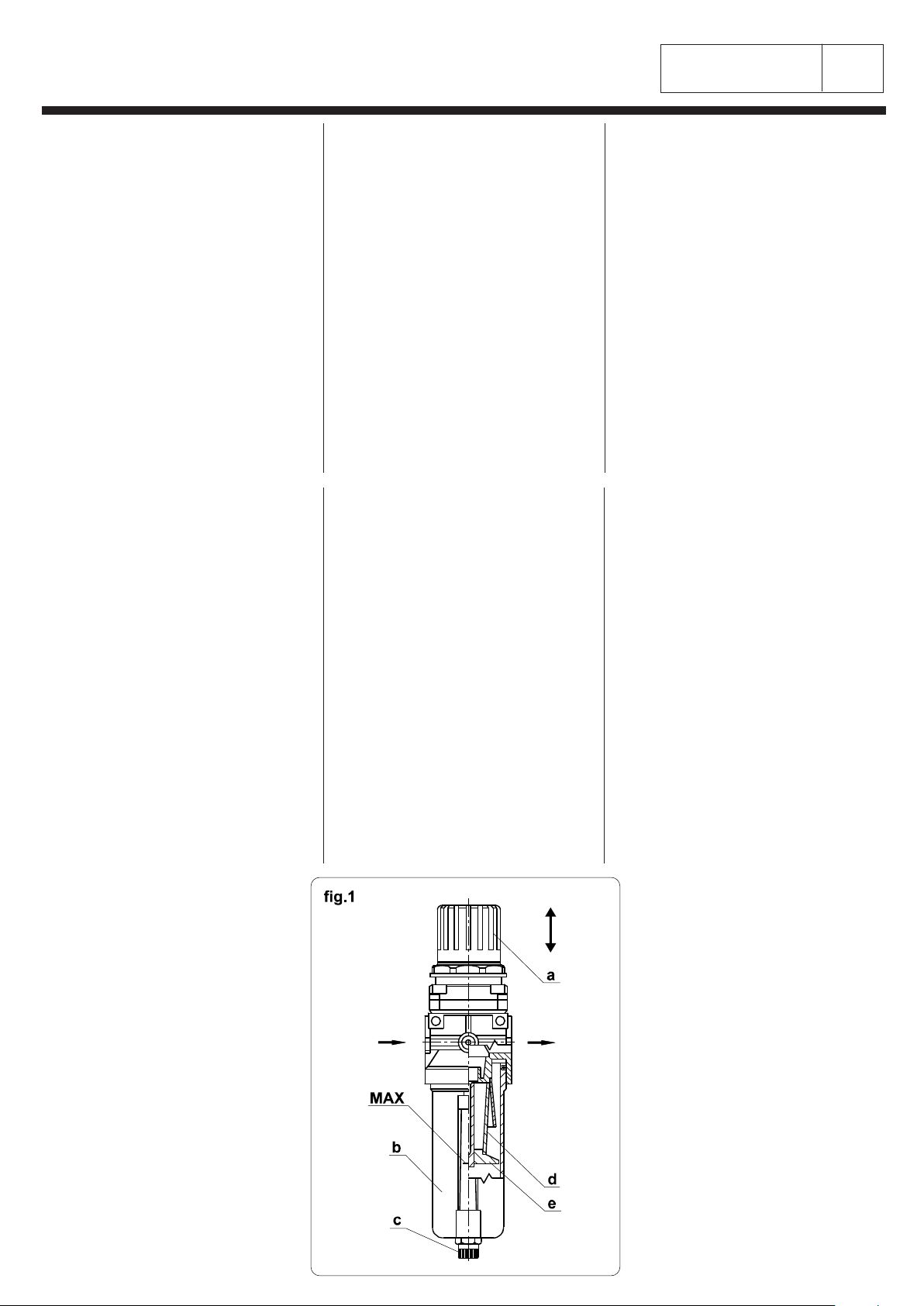
PRESSURE REGULATION (fig.1)
- Lift the handle "a".
- Rotate it in a sense or in the other, till when the proper
pressure in exit is obtained.
- Low the handle "a".
FILTER DRAINAGE (fig.1)
- On the glass it is indicated the MAX level. When its
contents of impurity reaches this level, unscrew the plug
"c" till when it is completely empty.
FILTER ELEMENT REPLACEMENT AND CLEANING
(fig.1)
- Interrupt the air flow.
- Unhook the glass "b".
- Unscrew the screen "e", clean or replace the filter "d".
- Screw again the screen "e".
- Hook again the glass "b".
- Let in the air flow.
TRAITEMENT DE L'AIR COMPRIME
L'air comprimé doit être:
1 - filtrée pour éviter le traînement de poussières et
humidité qui en créant des incrustations réduiseraient le
rendement et la durée des composants pneumatiques.
2 - réglée pour garantir l'entrée en machine à la pression
optimale.
REGLAGE DE LA PRESSION (fig.1)
- Soulever la poignée "a".
- La tourner dans un sens ou dans l'autre jusqu'à obtenir
la pression exacte en sortie.
- Baisser la poignée "a".
VIDAGE DU FILTRE (fig.1)
- Sur le verre est indiqué le niveau MAX. Quand le contenu
d'impuretés joint ce niveau, dévisser le bouchon "c"
jusqu'au vidage complet du même.
REPLACEMENT ET NETTOYAGE DE L'ELEMENT
FILTRANT (fig.1)
- Interrompre le débit d'air.
- Décrocher le verre "b".
- Dévisser l'écran "e", nettoyer ou remplacer le filtre "d".
- Révisser l'écran "e".
- Raccrocher le verre "b".
- Introduire le débit d'air.
TRATAMIENTO DEL AIRE COMPRIMIDO
El aire comprimido debe ser:
1 - filtrado para evitar que arrastre polvo y humedad, los
cuales creando sedimentos reducirian el rendimiento y
la vida de los componentes neumáticos.
2 - regulado para garantizar la entrada en máquina a la
presión optima.
REGULACION DE LA PRESION (fig.1)
- Alzar la manivela "a".
- Hacerla girar en un sentido o en el otro hasta obtener
la exacta presión en salida.
- Bajar la manivela "a".
DESCARGA DEL FILTRO (fig.1)
- Sobre el vaso está indicado el nivel MAX. Cuando el
contenido de impurezas llega al antedicho nivel, desenroscar
el tapón "c" hasta que el mismo este completamente vacio.
REEMPLAZO Y LIMPIEZA DEL ELEMENTO FILTRANTE
(fig.1)
- Interrumpir el flujo de aire.
- Desenganchar el vaso "b".
- Desenroscar la protección "e", limpiar o reemplazar el
filtro "d".
- Enroscar la protección "e".
- Reenganchar el vaso "b".
- Introducir el flujo de aire.
FILTRO - RIDUTTORE
FILTER - REDUCER
FILTRE - RÉDUCTEUR
FILTER - VERMINDERER
FILTRO - REDUCTOR
BEHANDLUNG DER PRESSLUFT
Die Pressluft muss sein:
1 - Filtriert, um Feuchtigkeits-und Staub-Transport zu
vermeiden, die Leistungsfaehigkeit und die Dauer der
pneumatischen Teile mit der Krustenbildung reduzieren
wuerden.
2 - Reguliert, um das Eintreten in Maschine zum optimalen
Druck.
DRUCKREGULIERUNG (Bild 1)
- Den Handgriff "a" heben.
- Er in einer Richtung oder in der anderen bis Erhaltung
des richtigen Drucks in Austritt drehen.
- Den Handgriff "a" senken.
FILTERENTLEERUNG (Bild 1)
- Auf dem Glas ist es das MAX Nieau angegeben. Wenn er
Inhalt von Unreinheiten dieses Niveau erreicht, den Verschluss
"c" bis kompletter Entleerung des selben abschrauben.
ERSETZUNG UND REINIGUNG DES FILTRIERENDES
ELEMENTS (Bild 1)
- Die Luftstroemung unterbrechen.
- Den Glas "b" abhaengen.
- Den Schirm "e" abschrauben, den Filter "d" reinigen
oder ersetzen.
- Den Schirm "e" wiederschrauben
- Den Glas "b" wiederhaengen.
- Die Luftstroemung zufuehren.
TRATTAMENTO DELL'ARIA COMPRESSA
L'aria compressa deve essere:
1 - filtrata onde evitare il trascinamento di pulviscolo ed
umidità che creando incrostazioni ridurrebbero il
rendimento e la durata dei componenti pneumatici.
2 - regolata per garantire l'entrata in macchina alla
pressione ottimale.
REGOLAZIONE DELLA PRESSIONE (fig.1)
- Sollevare la manopola "a".
- Ruotarla in un senso o nell'altro fino ad ottenere la esatta
pressione in uscita.
- Abbassare la manopola "a".
SCARICO DEL FILTRO (fig.1)
- Sul bicchiere è indicato il livello MAX. Quando il
contenuto di impurità raggiunge questo livello, svitare il
tappo "c" fino al completo svuotamento dello stesso.
SOSTITUZIONE E PULIZIA DELL'ELEMENTO
FILTRANTE (fig.1)
- Interrompere il flusso d'aria.
- Sganciare il bicchiere "b".
- Svitare lo schermo "e", pulire o sostituire il filtro "d".
- Riavvitare lo schermo "e".
- Riagganciare il bicchiere "b".
- Immettere il flusso d'aria.

n°
di 3
Pagina N°
60500.101.0202
RIPRODUZIONE VIETATA A TERMINI DI LEGGE - REPRODUCTION FORBIDDEN AS TO LAW TERMS
1
CAMBIO RIVESTIMENTI FORME
COVERING CHANGE
CHANGEMENT REVETEMENTS
BEKLEIDUNGEN ERSEZTUNG
CAMBIO REVESTIMIENTOS
Le forme sono rivestite con materiali atti a consentire
l'accoppiamento fra le stesse, la distribuzione ed il
passaggio omogeneo di aria e vapore.
I RIVESTIMENTI
Sono materiali di consumo che si deteriorano con
l'uso pertanto si consiglia di controllare periodicamente
l'efficienza. Rivestimenti deteriorati influiscono negativa-
mente sulla qualità dello stiro quindi devono essere
necessariamente sostituiti.
Per la loro sostituzione procedere come segue:
Escludere tutte le fonti di energia ed accertarsi
che le forme siano fredde
1 - Allentare e sfilare le molle tenditelo.
2 - Slegare la cordina tenditelo, togliere il telo ed eventuali
barrette metalliche nel bordo.
3 - Togliere i vari strati di rivestimento.
4 - Pulire le forme da eventuali residui curando di non
otturare i fori ed evitando l'entrata di corpi estranei.
5 - Sostituire i vari strati del rivestimento rispettando lo
stesso ordine e sistema di fissaggio originali. I rivestimenti
devono aderire perfettamente alle forme.
6 - I vari strati devono essere coperti dal telo esterno con
la sagoma della forma inserendo le eventuali barrette
metalliche, annodare poi le cordine inserite nel bordo ed
agganciare le molle tenditelo.
Si fornisce a richiesta:
- Kit teli di copertura confezionati, (per codici kit vedi tavola
successiva).
- Accessori qui di seguito elencati:
The shapes are covered with materials fit to consent the
matching between head and buck, as well as the distribution
and the homogeneus passage of the air and steam.
COVERINGS
They are expendable materials which deteriorate with
use, therefore it is advisable to check their efficiency
periodically. Deteriorated coverings have a negative
influence on the ironing quality therefore they must be
changed.
Follow following instructions for coverings replacement:
Exclude the electric energy and to be sure that
the shapes are cold.
1 - Ease-off and extract the covers-stretcher springs.
2 - Untie the covers-stretcher ropes, take off the cover
and the eventual metal bars from its edge.
3 - Take-off the different coverings layers.
4 - Clean the shapes and remove the original coverings
residuals, making sure not to close the holes and
avoiding the entrance of foreign matters.
5 - Replace the different coverings layers observing the
original order and fixing system.
6 - The different layers of the bucks must be covered
with the cover with shape template inserting the
eventual metal bars in its edge, tie the ropes and hook
the cover-stretcher spring.
It is supplies upon request:
- Manufactured covers kit, complete coverings kit (for kit
codes pls refer to the following table.
- Accessories listed here below:
Les formes sont revenues avec des matériaux adaptés à
permettre l'accouplement entre les mêmes, la distribution et
le passage d'air et de vapeur.
LES REVETEMENTS
Il s'agit de matériaux de consommation qui se détériorent par
l'utilisation, donc on conseille d'en vérifier périodiquement
l'efficacité. Des revêtements détériorés entrainent une
influence nêgative sur la qualité du repassage, donc ils
doivent être nécessariement remplacés.
Pour leur replacement procéder comme il suit:
Débrancher toute source d'énergie et s'assurer
que les formes soient froides.
1 - Lacher et défiler les ressorts de la housse.
2 - Détacher la corde de la housse, enlever la housse et
les éventuelles petites barres métalliques sur le bord.
3 - Enlever les différentes couches de revêtement.
4 - Nettoyer les formes des possibles résidus en faisant
attention de ne pas boucher les trous et en évitant
l'entrée de corps étrangers.
5 - Remplacer les différentes couches de revêtement en
respectant le même ordre et système de fixation originaux.
Les revêtements doivent adhérer parfaitement aux formes.
6 - Les différentes couches doivent être couvertes par la
housse extérieure, avec le profil de la forme par l'éventuelle
insertion des petites barres méttalliques, nouer après les
cordes insérées sur et accrocher les ressorts de la housse.
On livre sur demande:
- Ensemble housses confectionnées (pour référence
ensemble voir table suivante).
- Accessoires indiqués ci-dessous:
Die Formen sind mit Materialien verkleidet, die
Formenkupplung, die Verteilung und den gleichartigen
Durchgang von Luft und Dampf erlauben.
DIE BEKLEIDUNGEN
Es handelt sich um Verbrauchsmaterialien, die sich mit
dem Verbrauch verschlechtern deshalb wird man
beratet, periodisch die Leistungsfaehigkeit zu pruefen.
Verschlechterten Bekleidungen haben einen negativen
Einfluss auf der Buegelqualitaet, deshalb sollen sie
unbedingt ersetzt werden.
Fuer ihre Ersetzung wie folgt verfahren:
Alle Energiequellen ausschliessen und sicher
sein dass die Formen kalt sind.
1 - Die Feder Bezugspanner loesen und abziehen.
2 - Das Seil Bezugspanner losbinde, den Bezug und
eventuellen Metallbarren im Rand wegnehmen.
3 - Die verschiedenen Schichte der Bekleidung wegnehmen.
4 - Die Form von eventuellen Rueckstande reinigen
beim Beachten die Loecher nicht verstopfen und beim
Vermeiden des Eingangs von Fremdkoerper.
5 - Die verschiedenen Schichte der Bekleidung ersetzen,
beim Beachten der selben originalen Reihenfolge und
Fixierungssystem. Die Bekleidungen muessen an den
Formen perfekt anhaftend sein.
6 - Die verschiedenen Schichte der Unterflaeche muessen
mit dem Aussenbezug mit dem Profil der Form bedeckt
werden, beim Einfuehren von den eventuellen Metallbarren
in dem Rand, die Seile dann verknoten und die Haken
Bezugspanner anhaengen.
Bei Anfrage geliefert:
- Satz zubereiteten Bekleidungen (fuer Referenznummer
siehe folgende Tafel).
- Zubehoeren wie folgt angefuehrt:
Las formas están revestidas con materiales aptos para
permitir el acoplamiento entre las mismas, la distribución
y el pasaje homogéneo de aire y vapor.
LOS REVESTIMIENTOS
Son materiales de consumo que se deterioran con el uso,
por lo tanto se aconseja controlar periodicamente la
eficiencia de los mismos. Revestimientos deteriorados
influyen en modo negativo en la calidad del planchado y
por tanto deben ser necesariamente reemplazados.
Para el reemplazo de los revestimientos proceder como
sigue:
Excluir toda fuente de energia y asegurarse
que las formas esten frias.
1 - Aflojar y quitar los ganchos tensa-telas.
2 - Desatar el cordoncito tensa-telas, quitar la tela de
recubrimiento y eventuales barras de metal dal bordillo.
3 - Quitar por completo los revestimientos deteriorados.
4 - Limpiar las formas de eventuales residuos teniendo
cuidado de no obturar los agujeros y evitando que
entren cuerpos extraños.
5 - Reemplazar las varias capas de revestimientos
respetando el mismo orden y sistema de fisaje original. Los
revestimientos deben adherir perfectamente a las formas.
6 - Las varias capas de revestimiento deben ser cubiertas
por la tela de recubrimiento exterior hecha a perfil de la
forma e insertando las eventuales barras metálicas, luego
atar el cordoncito y enganchar los ganchos tensa-telas.
Se suministra, bajo pedido:
- Kit telas de recubrimiento confeccionados, (para código
kit ver tabla que sigue).
- Accesorios elencados de seguido:
Codice
Code Descrizione Description U.M.
40.141.103 Molla Ø8 L.= 165 mm. Spring Ø8 L.= 165 mm. NR
40.141.104 Molla Ø8 L.= 200 mm. Spring Ø8 L.= 200 mm. NR
40.141.105 Molla Ø8 L.= 320 mm. Spring Ø8 L.= 320 mm. NR
65.812.101-10 Barretta Ø4 L.= 350 mm. Rod Ø4 L.= 350 mm. NR
65.812.101-11 Barretta Ø4 L.= 500 mm. Rod Ø4 L.= 500 mm. NR
65.812.101-12 Barretta Ø4 L.= 700 mm. Rod Ø4 L.= 700 mm. NR
65.812.101-13 Barretta Ø4 L.= 800 mm. Rod Ø4 L.= 800 mm. NR
65.812.101-14 Barretta Ø4 L.= 900 mm. Rod Ø4 L.= 900 mm. NR
65.812.101-15 Barretta Ø4 L.= 1000 mm. Rod Ø4 L.= 1000 mm. NR
90.180.100 Tubetto adesivo Bostik Tube of adhesive Bostik NR
90.180.108 Tubetto silicone Tube of silicone NR
65.811.101 Cordina in poliestere Ø3 Polyester string Ø3 MT

n°
di 3
Pagina N°
60500.101.0202
RIPRODUZIONE VIETATA A TERMINI DI LEGGE - REPRODUCTION FORBIDDEN AS TO LAW TERMS
2
CAMBIO RIVESTIMENTI FORME
COVERING CHANGE
CHANGEMENT REVETEMENTS
BEKLEIDUNGEN ERSEZTUNG
CAMBIO REVESTIMIENTOS
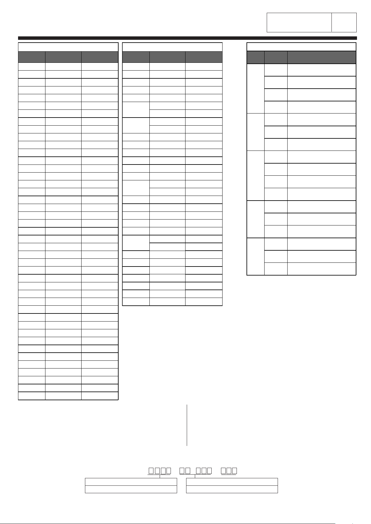
Nella tabella "A" indichiamo con un numero (80-82-ecc.) il tipo di rivestimento
standard o extra di ogni singola forma.
Nella tabella "B" indichiamo il codice parziale per l'ordinazione del rivestimento
completo o delle parti che lo compongono.
Per l'ordinazione seguire l'esempio riportato sotto.
N.B.: La rete in alluminio non è prevista come materiale di usura; a richiesta
viene fornita utilizzando il codice N°65.210.101 (rete in alluminio altezza 1 mt.)
indicando la metratura desiderata.
On table "A" we show with a number (80-82 etc.) the type of covering, standard
or special, for each single shape.
On table "B" we show the partial reference number for ordering the complete
covering or the parts composing it.
For order follow the example indicated below.
N.B.: The aluminium gauze ist not considered as wear material; by request it
can be supplied by using reference number N°65.210.101 (aluminium gauze
1 mt height) by indicating the desired height.
Composizione codice di ordinazione
Composition order reference number
...
INSERIRE CODICE TAB."B"
INSERT REF. N° TAB."B"
INSERIRE N° FORMA TAB."A"
INSERT SHAPE N° TAB."A"
Es. 2071.10.001.316 TELO DI COPERTURA
Ex. 2071.10.001.316 COVER CLOTH
316
TABELLA - TABLE "A"
N°FORMA
SHAPE N° STANDARD 20
EXTRA
0080 80 82
0081 80 82
0204 81 83
0213 81 83
0506 80 82
0718 80 82
0800 81 83
0802 81 83
0981 80 82
0982 80 82
0983 80 82
0984 80 82
1109 80 82
2018 81 83
2040 81 83
2041 84 -
2048 84 -
2056 81 83
2057 81 83
2058 84 83
2061 81 83
2062 81 83
2064 81 83
2065 81 83
2066 81 83
2071 81 83
2074 81 83
2075 81 83
2077 84 -
2079 81 83
2080 81 83
2081 80 82
2082 81 83
2083 81 83
2084 81 -
2085 81 -
2086 2048: 84 -
2084: 81
2087 84 -
2088 84 -
2089 84 -
2090 84 -
2091 84 -
2092 81 83
2093 81 83
2094 81 83
2099 84 -
TABELLA - TABLE "A"
N°FORMA
SHAPE N° 10
STANDARD 20
EXTRA
2153 - -
2154 - -
2159 81 83
2160 84 83
2167 81 83
2168 81 83
2169 80 82
2170 - -
2183 - -
2186 81 83
2187 81 83
2188 81 83
2189 84 83
2190 - -
2192 81 83
3243 80 82
3244 81 83
3245 81 83
3246 84 83
3247 80 82
3248 84 83
3249 84 83
3250 0800: 81 83
3249: 84
4019 80 82
4020 PRONTOTOP cod. / ref. 4020.19
4022 80 82
4024 81 83
4025 81 83
4030 - -
5002 81 83
5007 - -
7702 80 82
7705 80 82
7706 80 82
7707 80 82
7708 80 82
7709 80 82
7710 80 82
7711 80 82
7712 80 82
7714 80 82
7715 80 82
8107 PRONTOTOP cod. / ref. 8107.19
8108 80 82
8109 80 82
8115 80 82
TABELLA - TABLE "B"
TIPO
TYPE
CODICE
CODE
DESCRIZIONE
DESCRIPTION
80
10.000 Rivestimento completo
Complete covering
10.001 Telo di copertura
Covering fabric
10.002 Schiumato blu
Blue foam padding
10.003 Mollettone
Padding
81
10.000 Rivestimento completo
Complete covering
10.001 Telo di copertura
Covering fabric
10.003 Mollettone
Padding
82
20.000 Rivestimento completo
Complete covering
10.001 Telo di copertura
Covering fabric
10.002 Schiumato blu
Blue foam padding
20.004 Gomma al silicone
Silicon rubber
83
20.000 Rivestimento completo
Complete covering
10.001 Telo di copertura
Covering fabric
20.004 Gomma al silicone
Silicon rubber
84
10.000 Rivestimento completo
Complete covering
10.001 Telo di copertura
Covering fabric
10.003 Felpatino
Plushing
n°
di 3
Pagina N°
60500.101.0202
RIPRODUZIONE VIETATA A TERMINI DI LEGGE - REPRODUCTION FORBIDDEN AS TO LAW TERMS
3
CAMBIO RIVESTIMENTI FORME
COVERING CHANGE
CHANGEMENT REVETEMENTS
BEKLEIDUNGEN ERSEZTUNG
CAMBIO REVESTIMIENTOS
Nella tabella "A" indichiamo con un numero (80-82-ecc.) il tipo di rivestimento
standard o extra di ogni singola forma.
Nella tabella "B" indichiamo il codice parziale per l'ordinazione del rivestimento
completo o delle parti che lo compongono.
Per l'ordinazione seguire l'esempio riportato sotto.
N.B.: La rete in alluminio non è prevista come materiale di usura; a richiesta
viene fornita utilizzando il codice N°65.210.101 (rete in alluminio altezza 1 mt.)
indicando la metratura desiderata.
On table "A" we show with a number (80-82 etc.) the type of covering, standard
or special, for each single shape.
On table "B" we show the partial reference number for ordering the complete
covering or the parts composing it.
For order follow the example indicated below.
N.B.: The aluminium gauze ist not considered as wear material; by request it
can be supplied by using reference number N°65.210.101 (aluminium gauze
1 mt height) by indicating the desired height.
Composizione codice di ordinazione
Composition order reference number
...
INSERIRE CODICE TAB."B"
INSERT REF. N° TAB."B"
INSERIRE N° FORMA TAB."A"
INSERT SHAPE N° TAB."A"
Es. A001.10.001.316 TELO DI COPERTURA
Ex. A001.10.001.316 COVER CLOTH
316
TABELLA - TABLE "A"
N°FORMA
SHAPE N° 10
STANDARD 20
EXTRA
A001 81 83
A002 81 83
A005 80 82
A006 81 83
A008 80 82
A009 84 83
A010 80 82
A011 80 82
A012 80 82
A013 80 82
A014 81 83
A016 84 83
A017 - -
A019 80 82
A020 81 83
A021 80 82
A022 81 83
A023 81 83
A024 80 82
A025 80 82
A026 81 83
A027 81 83
A030 84 83
A031 80 82
A032 80 82
A033 80 82
A034 80 82
A035 81 83
A036 81 83
A037 80 82
A038 80 82
A041 81 83
A042 80 82
A043 81 83
A044 80 82
A045 - -
A046 - -
A047 81 83
A048 80 82
A049 80 82
A050 80 82
A052 80 82
A053 80 82
TABELLA - TABLE "A"
N°FORMA
SHAPE N° 10
STANDARD 20
EXTRA
A054 80 82
A055 81 83
A056 80 82
A057 81 83
A060 81 83
A061 2170: - -
2075: 81 83
A062 5002: 81 83
2099: 84 -
A063 81 83
A064 80 82
A065 81 83
A066 80 82
A067 81 83
A068 81 83
A069 2153: - -
2074: 81 83
A070 81 83
A072 80 82
A074 81 83
A075 80 82
A078 81 83
A080 2077: 84 -
0802: 81 83
A081 84 83
A082 84 83
A084 84 -
A085 80 82
A086 80 82
A087 81 83
A088 81 83
TABELLA - TABLE "B"
TIPO
TYPE
CODICE
CODE
DESCRIZIONE
DESCRIPTION
80
10.000 Rivestimento completo
Complete covering
10.001 Telo di copertura
Covering fabric
10.002 Schiumato blu
Blue foam padding
10.003 Mollettone
Padding
81
10.000 Rivestimento completo
Complete covering
10.001 Telo di copertura
Covering fabric
10.003 Mollettone
Padding
82
20.000 Rivestimento completo
Complete covering
10.001 Telo di copertura
Covering fabric
10.002 Schiumato blu
Blue foam padding
20.004 Gomma al silicone
Silicon rubber
83
20.000 Rivestimento completo
Complete covering
10.001 Telo di copertura
Covering fabric
20.004 Gomma al silicone
Silicon rubber
84
10.000 Rivestimento completo
Complete covering
10.001 Telo di copertura
Covering fabric
10.003 Felpatino
Plushing

n° 1
70200.104.0304 di 1
Pagina N°
RIPRODUZIONE VIETATA A TERMINI DI LEGGE - REPRODUCTION FORBIDDEN AS TO LAW TERMS
IMPIANTO PNEUMATICO
PNEUMATIC PLANT
INSTALLATION PNEUMATIQUE
PNEUMATISCHE ANLAGE
INSTALACION NEUMÁTICA
Pos. Codice
Code DESCRIZIONE DESCRIPTION Q.tà
12.102.46.001 Cilindro Ø 20 x 50 D.E. Cylinder Ø 20 x 50 D.E. 1
2.102.46.001-01 Serie standard guarnizioni Kit of gaskets -
2 2.101.46.001 Cilindro Ø 16 x 30 D.E. Cylinder Ø 16 x 30 D.E. 1
3 45.600.200 Filtro riduttore Ø 1/4" Filter reducer Ø 1/4" 1
4 45.600.141 Manometro Ø 1/8" Pressure gauge Ø 1/8" 1
545.216.451 Regolatore di flusso unidirezionale Ø 1/8" 1-way flow regulator Ø 1/8" 4
45.216.451-01 Serie standard Kit of spares -
6 45.200.140 Silenziatore Ø 1/8" Silencer Ø 1/8" 4
7 45.407.860 Elettrovalvola a 5 vie 220V 50/60Hz 5-way solenoid valve 220V 50/60Hz 2
- 15.500.200 Tubo di nylon Ø 6 x 4 azzurro L.= mt. Blue nylon tube Ø 6 x 4 L.= mt. -
SIMBOLO
SYMBOL
SYMBOLE
FUNZIONE FUNCTION FONCTION
C1 CILINDRO DEFLETTORI DEFLECTORS CYLINDER CYLINDRE DEFLECTEURS
C2 CILINDRO PALETTE VANES CYLINDER CYLINDRE PALETTES
FR FILTRO - RIDUTTORE PRESSIONE D'ESERCIZIO FILTER - REDUCER WORKING PRESSURE FILTRE - REDUCTEUR PRESSION DE SERVICE
H1 MANOMETRO PRESSIONE D'ESERCIZIO WORKING PRESSURE GAUGE MANOMETRE PRESSION DE SERVICE
RF REGOLATORI DI FLUSSO FLOW REGULATORS REGULATEURS DE DEBIT
yv1 ELETTROVALVOLA ASPIRAZIONE
(RIFERIMENTO SCHEMA ELETTRICO)
VACUUM SOLENOID VALVE
(REFERENCE ELECTRICAL PLAN)
ELECTROVANNE ASPIRATION
(REFERENCE SCHEMA ELECTRIQUE)
yv2 ELETTROVALVOLA SOFFIAGGIO
(RIFERIMENTO SCHEMA ELETTRICO)
BLOWING SOLENOID VALVE
(REFERENCE ELECTRICAL PLAN)
ELECTROVANNE SOUFFLAGE
(REFERENCE SCHEMA ELECTRIQUE)
SYMBOL
SYMBOLE FUNKTION FUNCION
C1 ZYLINDER SCHIRM CILINDRO DEFLECTORES
C2 ZYLINDER SCHAUFEL CILINDRO PALETAS
FRL FILTER - VERMINDERER BETRIEBSDRUCK FILTRO - REDUCTOR PRESION DE SERVICIO
H1 MANOMETER BETRIEBSDRUCK MANOMETRO PRESION DE SERVICIO
RF FLUSSREGLERS REGULADORES DE FLUJO
YV1 ELEKTROVENTIL ABSAUGUNG
(SIEHE ELEKTRISCHE PLAENE)
ELECTROVALVULA ASPIRACION
(REFERENCIA ESQUEMA ELECTRICO)
YV2 ELEKTROVENTIL BLASEN
(SIEHE ELEKTRISCHE PLAENE)
ELECTROVALVULA SOPLADO
(REFERENCIA ESQUEMA ELECTRICO)

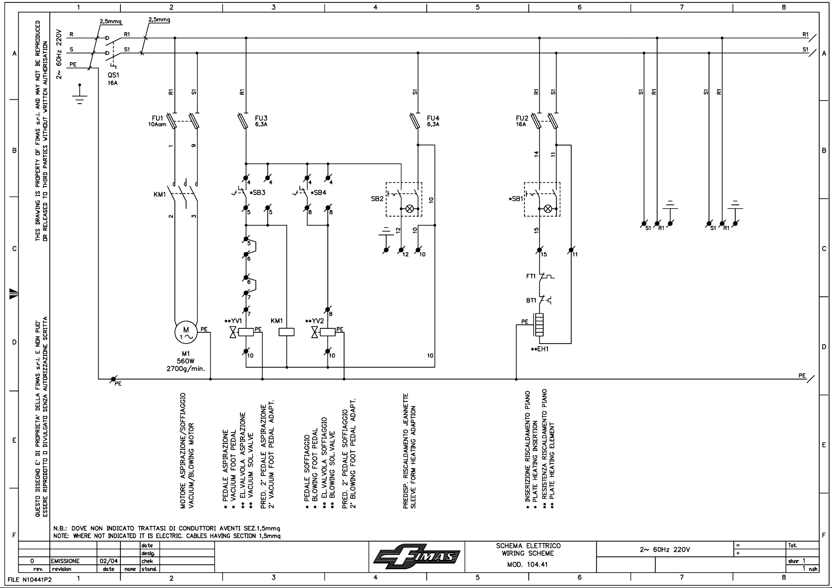

This manual suits for next models
1


