FINE INSTRUMENTS CORPORATION FINEST 716 User manual
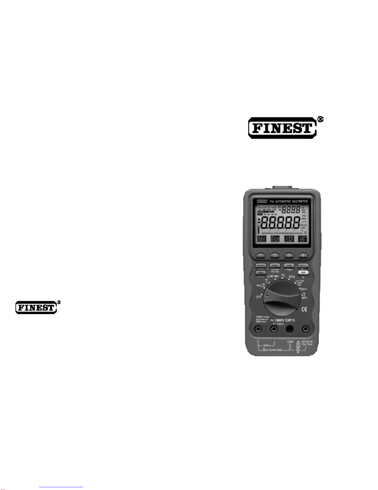
Model 716
Automotive Multimeter
USER’S
MANUAL
FINE INSTRUMENTS CORPORATION
FINE INSTRUMENTS CORPORATION
341-5, SONGNAE-DONG, SOSA-GU, BUCHON-SHI, KYUNGGI-DO
KOREA
-TEL: (82-32) 668-6042 -FAX: (82-32) 656-5844
-E-mail: [email protected]
© Copyright 2003 Fine Instruments Corp. All right reserved.
Specifications subject to change without notice.
Litho in Korea.
a world leader in test & measurement

1
Basic Specifications
DC Voltage : 0 to 1000 V
AC Voltage : 0 to 1000 V (40 Hz to 2 kHz)
Basic Accuracy : DC voltage – 0.1 %
AC voltage – 0.5 %
RPM (4-stroke) : 120 to 20000 RPM
RPM (DIS & 2-stroke) : 60 to 10000 RPM
DC Current : 0 to 10 A (20 A for 30 seconds)
AC Current : 0 to 10 A (20 A for 30 seconds)
Resistance : 0 to 50 M
Frequency : 0.5 Hz to 1 MHz
Duty Cycle : 0 to 99.9 %
Dwell : 0 to 356.4
Pulse Width : 0.50 ms to 250.00 ms
Diode Test : 3.0 V
Temperature : – 50 C to 1,300 C (– 58 F to 2,372 F)
Audible Continuity Test : For quick open-short test
O
2
Sensor Test : For qu
i
ck a nd accu rat e d
i
a gno sin g a nd
simulating O
2
sensors
Ground Test : For
l
oca t
i
n g ba d gr oun ds, vol tag e dr op s,
intermittent connections or any source of high
resistance in automotive electrical circuits and
grounds
Charging System Test : For diagnosing battery and alternator
Battery Drain Test :
For measuring the car’s battery current when it is
turned off.
SOURCES LIKE SMALL HAND-HELD RADIO
TR ANSCEI VERS, FIXED STA TION RA DI O
AND TELEVISION TRANSMITTERS, VEHICLE
RA DIO TR ANSM IT TERS AND CEL LUL AR
PHONES GENERATE ELECTROMAGNETIC
RADIATION THAT MAY INDUCE VOLTAGES
IN THE TEST LEADS OF THE MULTIMETER.
IN SU CH CASES THE ACCURA CY OF T HE
MULT IMETER C ANNOT BE G UARAN TEED
DUE TO PHYSICAL REASONS.
WARNING!
Warning
Read
¡°
Safety Information” before using this Meter.
32
This manual contains information and warnings that must be followed for operating
the meter safely and maintaining the meter in a safe operating condition.
If
the meter is not used in a manner specified in this manual,
the pro
t
ection
provided by the meter may be impaired.
This meter complies
with the requirements for double insulation
t
o IEC 1010-1 (2001),
UL 3111-1 (6, 1994), EN 3121-1
(1998), CSA C
22.2
No.
1010-1-92 ; Overvoltage
1000 V
Category II and also the E.M.C.
standards to EN61326 : 1997+A
1
.
TERMS IN THIS MANUAL
A
Warning
identifies conditions and actions that could pose serious hazards to the
user. A Caution identifies conditions and
actions that could cause damage
the
meter or the vehicle under test. Notes are added to provide clarity and helpful tips.
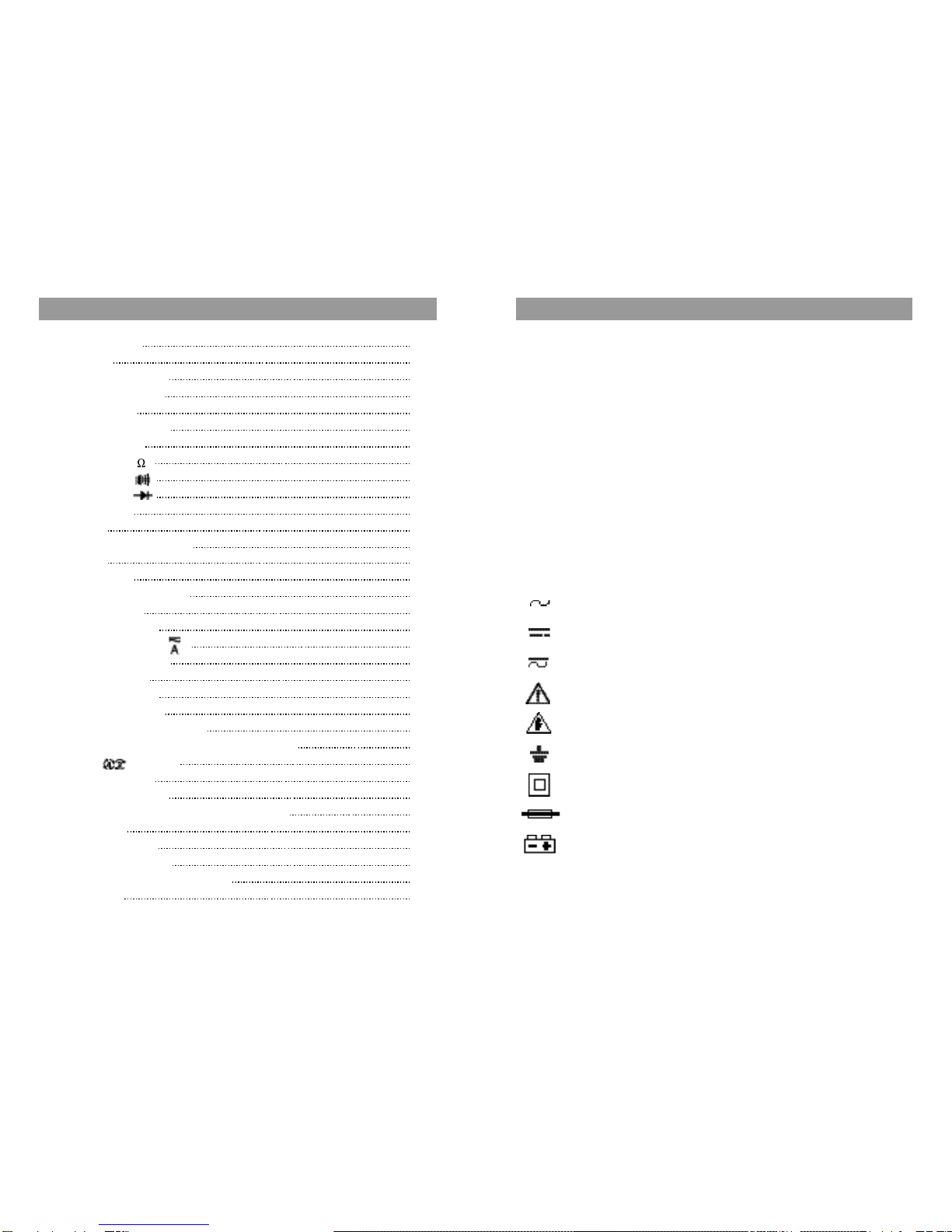
INTERNATIONAL ELECTRICAL SYMBOLS
AC (Alternating Current)
DC (Direct Current)
Either DC or AC
Caution! Refer to the explanation in the manual.
Dangerous voltage (Risk of electric shock)
Earth (Ground)
Double insulation or Reinforced insulation
Fuse
Battery
1. SAFETY INFORMATION
1. Safety Information 3
2. Introduction 6
3. Controls and Indicators 8
4. Basic Meter Functions 12
4-1. Voltage (V) 13
4-2. Dual Display RPM 14
4-3. Temperature 15
4-4. Resistance ( ) 16
4-5. Continuity ( ) 17
4-6. Diode test ( ) 18
4-7. Frequency 19
4-8. RPM 20
4-9. Fuel Injection On Time 21
4-10.Dwell 22
4-11.Duty Cycle 23
4-12.Charging System Test 24
4-13.Ground Test 26
4-14.O2 Sensor Test 28
4-15.AC or DC Current ( ) 30
4-16.Battery Drain Test 31
5. Advanced Features 32
5-1. MIN/MAX Mode 32
5-2. 1 ms Peak Mode 32
5-3. Manual and Auto Ranging 33
5-4. Trigger Level and +/- Trigger Slope Selection 33
5-5. RPM Selection 34
5-6. Relative Mode 34
5-7. Hold or Auto Hold 34
5-8. Memory (Data Store, Recall, & Clear) Mode 35
5-9. Backlight 36
5-10.Auto-Power-Off 36
5-11.RS-232C Interface 37
6. Maintenance and Replaceable Parts 38
7. Specifications 40
CONTENTS
4 5
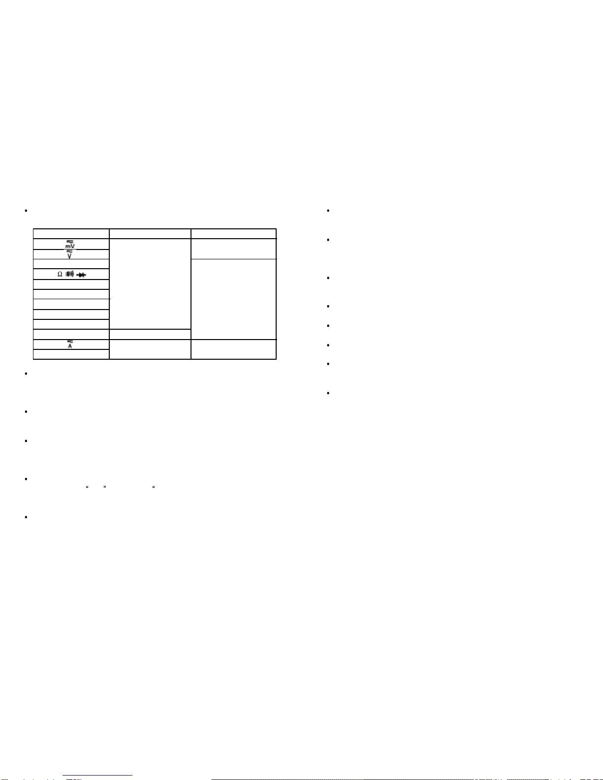
WARNING
To avoid electrical shock hazard or damage to the meter, do not exceed the input
limits shown in the table below :
Observe the proper safety precautions when working with voltages above 60 V
DC or 25 V AC rms to avoid an elec
t
rical shock. These voltage levels pose
a
potential shock hazard to the user.
Wear an
ANSI
eye shield when testing or repairing vehicles. Objects can be
propelled by whirling engine components.
Inspect
test leads,
connectors, and probes for damaged insulation or exposed
metal before using the instrument. If any de
f
ects are found, replace
them
immediately.
Never attempt a voltage measurement with the test leads inserted into the “A”
terminal and the
COM terminal. The A” terminal is protected by a
f
use. You
might be injured or damage the meter.
Turn the engine off before connecting or disconnecting inductive pickup to avoid
a shock.
FUNCTION
Temperature
Hz
ms-Pulse
Dwell
Duty Cycle
Elec, O
2
RPM
Battery Drain
TERMINALS
& COM
RPM + & -
A & COM
MAXIMUM INPUT
1000 V DC or 1000 Vpeak
600 V DC or
600 V AC rms
10 A / 600 V
VWHzms
Elec Temp
CAUTION
Disconnect the test leads from the test points before changing functions to avoid
damaging the meter when testing above 350 V AC.
Choose the proper range and function for the measurement
.
Always set
t
he
meter to the highest range and work downward for an unknown value if you are
using manual ranging mode.
Do not try voltage or current measurements that may exceed the ratings marked
on the input limit for switch or terminal.
Use current probes to measure circuits exceeding 10 A.
Disconnect the “live” test lead before disconnecting the “common” test lead.
Do not test a recently recharged lead-acid battery.
Disconnect the power and discharge all high-voltage capacitors before testing in
the resistance, continuity, and diode functions.
If the engine has been running, do not place the meter and its accessories near
the engine
or
t
he exhaust manifold which might be hot and can
damage the
meter.

76
This meter is a handheld and battery operated professional automotive multimeter
des igned to provide
troubles hooting solutions
t
o the most dif
f
icul t problems
encountered with today’s sophisticated automotive electronic systems.
The User’s Manual tells you how to use this meter. You may also need a manual
that provides technical information for the vehicle you
plan to
test. The
most
important information resources are the vehicle’s repair service manuals generally
available for purchase through automotive dealers. They are also available through
a number of publishers that specialize in providing technical information manuals to
the independent repair garages.
This User’s Manual should be used as a guide to get you started in troubleshooting.
Your real learning can best be accomplished through experience. As you become
more proficient in using the automotive multimeters to
t
roubleshoo
t
, you will very
quickly learn how certain
electrical symptoms can relate
to various driveability
problems.
This meter is much more than a standard multimeter. This meter can replace the
following several automotive testers.
Full Function Multimeter
O
2
-Sensor Tester
(PFI type or TBI type) Fuel Injector Tester
Battery Drain Tester
Ground Tester
Charging System Tester
Especially, this me
t
er
gets a
quick
and accura
t
e diagnosis of the complete O
2
circuit. This me
t
er is capable of
sending
a Rich/Lean
signal to the ECM, and
displaying crossing-per-second (CC) and O
2
voltage simultaneously,
when the
secondary display shows test results.
This meter has a bright LED backlight as well as enhanced LCD with larger digits,
wide viewing angle and on screen menu selection
.
A ba
t
tery access door allows
us er s to replace the battery and fus e
wit hout v oiding c al ibrat ion seals .
Overmoulding technology in the case disperses various shock over more of the
case than a conventional rubber boot design. Convenient closed case calibration
allows adjustments to be made directly through the RS-232C port.
2. INTRODUCTION
FEATURES
4
4
/
5
digit, 50000 count (primary) and 9999 count (secondary) dual display with
bar-graph. (Frequency range : 99999 counts)
Closed case calibration through the phototronic RS-232C serial port.
Accurate RPM measurements for 2- and 4-stroke automotive engines with 1 to
12 Cylinders using the Inductive Pickup.
ms-Pulse Width function to test on-time of both
P
FI
t
ype and TBI type
fuel
injectors, idle air control motors, and electronic transmission controls.
Du
t
y
Cycle and direct
DWELL reading for electronic fuel injection,
feedback
carburetors, and ignition systems.
4 steps
adjustable
triggers on 1 to 12 Cylinders,
ei ther 2- or 4-Cycl e for
outboards, motorcycles and conventional engines.
Measure
temperature of
fan switch and
catalytic converters up to 2,372 F
(1,300 C).
O
2
Sensor test for a quick diagnosis and simulation of the complete O
2
Sensor.
Ground test to locate bad ground, voltage drops, intermittent connections, or any
source of high resistance in automotive electrical circuits and grounds.
Charging system test to diagnose the battery and the alternator.
Battery drain test to measure the car’s battery current when it is turned off.
Auto Hold, 50 ms highspeed MIN/MAX/AVG, and Relative mode.
1 ms Peak mode.
Memory store and recall (20 locations).
Backlit display.
Auto-power-off.
RS-232C phototronic serial port.
Overmoulded case.
IEC 1010-1, CAT II 1000 V rating.

98
1. LCD display 4
4
/
5
digit, 50000 count (primary) and 9999 count (secondary)
dual display with bar-graph
2. On screen menu selection pushbuttons
3. Press this pushbutton momentarily to select
trigger lev els.
Pres s this pushbutton for more
t
han 1 second to toggle
between positive and negative trigger slopes.
4. Press this pushbutton momentarily to toggle between RPM
and RPM in RPM function. Press this pushbutton for more
than 1 second to select Relative Zero.
5. Press
this
pushbutton momentarily
t
o select Memory mode.
Press this pushbutton for more than 1 second to turn the LCD
backlight on.
6. Selector Turn the power On or Off and select a functions.
7. COM Common (Ground re
f
erence) input
t
erminal for all
functions
except RPM function
8. Input terminal for all
f
unctions except Current and
RPM
functions
9. Input
t
erminal (+)
for
RPM function. Output terminal for
s ending
out a Rich c ommand or a Lean c ommand for 5
seconds in O
2
Sensor test mode.
10. A/RPM- Input terminal (+)
f
or current
f
unction. Ground reference
(-)
input terminal for RPM function.
11. Press this pushbutton momentarily
to ac tivate
HOLD for
simply freezing a reading.
Press this pushbutton for more than 1 second to activate Auto
Hold for automatically capturing a stable reading, beeping to
acknowledge, and holding it on the LCD.
12. Press this pushbutton momentarily to activate Record function.
Press this pushbutton for more than 1 second to activate 1 ms
Peak function.
3. CONTROLS AND INDICATORS
14
1
2
3
4
5
6
7
8
13
12
11
10
9
V Hz ms
Elec Temp
RPM + /
Signal

13.
P
ress this pushbut
t
on momentarily to
selec
t
ranges in the
manual ranging mode of most functions or number of cylinders
on Dwell function. Press this pushbutton momentarily to toggle
between the PFI mode and the TBI mode when measuring on-
time of fuel injectors.
Press this pushbutton
f
or more than 1 second to toggle
Auto/Manual ranging in most functions.
14. RS-232 Optical interface
15. Menu on screen
16. These annunciators indicate trigger level status.
17. These annunciators indica
t
e that positive (+) or
negative (-)
Trigger Slope is selected.
18. This symbol indicates Negative Polarity.
19.
This symbol indicates the Relative function is activated.
20. DATA Primary digital readings of data being measured.
21. This annunciator indicates Autoranging.
22. AC DC AC annunciator indicates alternating current is selected.
DC annunciator indicates direct current is selected.
23. This annunciator indicates the Memory function is activated.
24. annunciator indicates the HOLD functions is selected
and annuncia
t
ors indicate the Auto
Hold
f
unction
is selected.
25. 1 ms MAX MIN These annunciators indicate 1 ms MAX (+) Peak, or 1 ms MIN
(-) Peak reading is being displayed.
26. MAX MIN AVG These annunciators indicate MAX (Maximum), MIN(Minimum),
or AVG(Average) reading is being displayed.
27. Chrg This annunciator indicates the Charging system test function is
selected.
28. Gnd This annunciator indicates the Ground test
function is
selected.
29. O
2
This annunciator indicates
t
he O
2
Sensor test function is
selected.
30. BatDr This annuncia
t
or
indicates the
Battery Drain
t
est function is
selected.
31. This symbol indicates the Diode test function is selected.
32. This symbol indicates the Continuity test function is selected.
33. Low Battery alert. Replace the battery as soon as possible to
ensure accuracy.
34. DATA Secondary display for Dual Display data.
35. CC... These annunciators indicate the function being selected and/or
the appropriate measurement units.
36. Analog bar-graph with scale.
10 11
+ –
TRIG
1312
Making Measurements and Tests
All measurements and tests are made by first setting the rotary selector switch to a
function setting (so that the meter is put in the default measurement function) and
then selecting a measurement from the menukeys. Note that not all function knob
settings have corresponding menukey settings.
For example, the steps below show how to make an ac voltage measurement.
1. Set the rotary selector switch to position for voltage measurements.
Then, the meter is set to the default dc voltage measurement mode.
2. Select the menukey 2 for ac voltage measurement.
3.
Connect the test leads to the measurement points.
4. BASIC METER FUNCTIONS
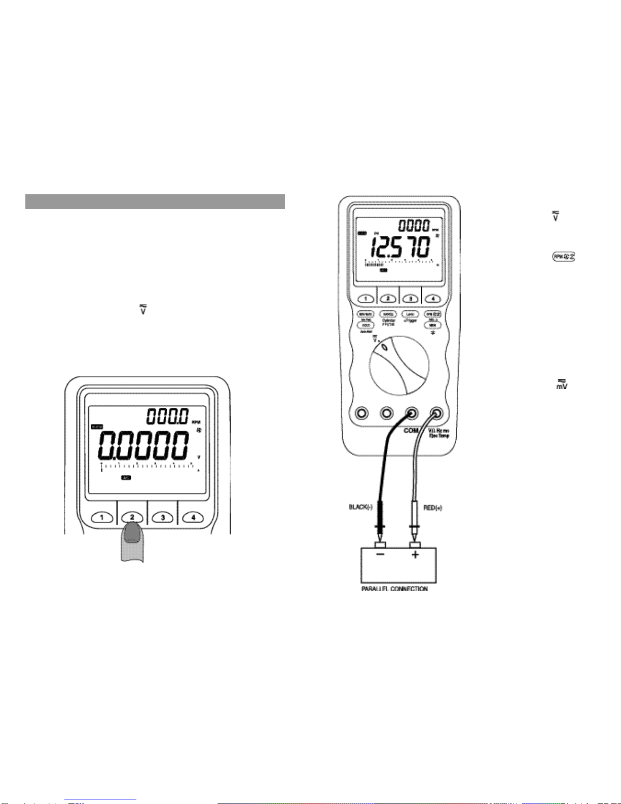
4-1. Voltage (V)
1. Set rotary selector to position.
The meter defaults at DC.
2. Press menukey
2 momen
t
arily to
select AC, and press twice
to sel ect H z in the secondary
display, if required.
3. Insert red lead into V terminal and
black lead into COM terminal.
4. Touch black probe to
ground
or
neg ativ e s ide
of the circ ui t and
touch red probe to positive side of
the circuit coming from the power
source.
5. Set rotary selector to
position
for voltage application below 0.4 V
with similar operation procedures.
6. Refer to 4-2 for c onvenient dual
display RPM function.
NOTE: Voltage must be measured
in p arallel (r ed prob e
measuring
circuit from
power source).
The analog bar graph is easier to read
when the da
t
a caus es the digi tal
display to
rapidly change.
It is al so
useful for trend setting
or direc tional
data.
1514
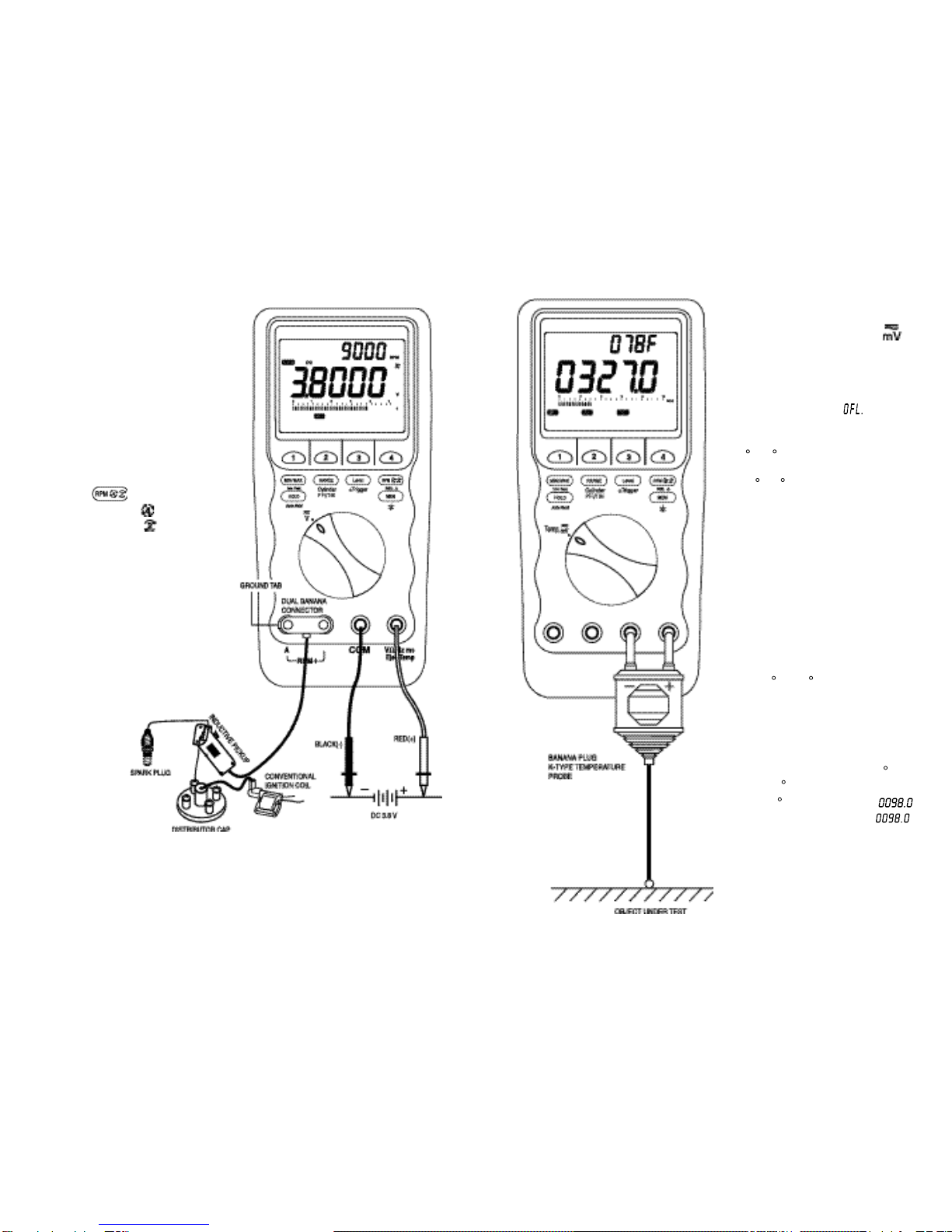
4-2. Dual Display RPM
T his function
i s avai lable
for the
primary functions ; DC mV, AC mV, DC
V, AC V, Dwell, ms-Pulse, and Duty
Cycle. The trigger level selection is not
available for this function, but available
for the primary display RPM function.
See 4-8 for more details.
1. Set the meter to the corresponding
primary function.
2. Press bu
t
ton to toggl e
between RPM (for 4-s
t
rok e
engine) and RPM
(for 2-stroke or
DIS engine).
3. Insert the Dual Banana Connector
into the RPM – and the R
P
M +
input terminals as shown. Ensure
the plug with the Ground Tab goes
into the RPM – terminal.
4. Clamp the induc
t
ive pi ckup to a
spark plug wire with the arrow sign
facing the spark plug as shown.
Ens ure
t
he pic kup
jaws ar e
completely closed.
4-3. Temperature
1. Se
t
rotary selector to Temp.
position.
2. Pres s menukey
3(or 4) to select
temperature function. The
primary
displ ay wi ll show and t he
secondary display will always show
the meter’s internal temperature in
C or F alternatively matching with
the selected primary display mode
of C or F.
3.
I
ns e r
t
banana plug K- ty pe
temperature
bead probe w ith
correct + / - polarities. You can also
use a thermocouple probe adapter
(optional accessory) to adapt other
st andard K-t y pe t empera ture
probes.
4. Touch the end of the thermocouple
probe to the measurement surface
and read the primary digital display
wit h C (or F). We c an ea s ily
recognize the temperature uni
t
of
the pri ma ry dis play
f
rom the
secondary display.
NOTE: The measured temperature
is
displayed with 0.1 C (or
0.1 F) reso
l
ution.
For example,
98 C is displayed as
and 98 F is d
i
sp
l
ayed .
5. Read RPM in the secondary display.
NOTE:
Position the pickup as far away from the distributor and the exhaust
manifold as possible.
Pos
i
tion the pickup with
i
n 6 inches of the spark plug or move it to
another plug wire if no reading or an erratic reading is received.
1716
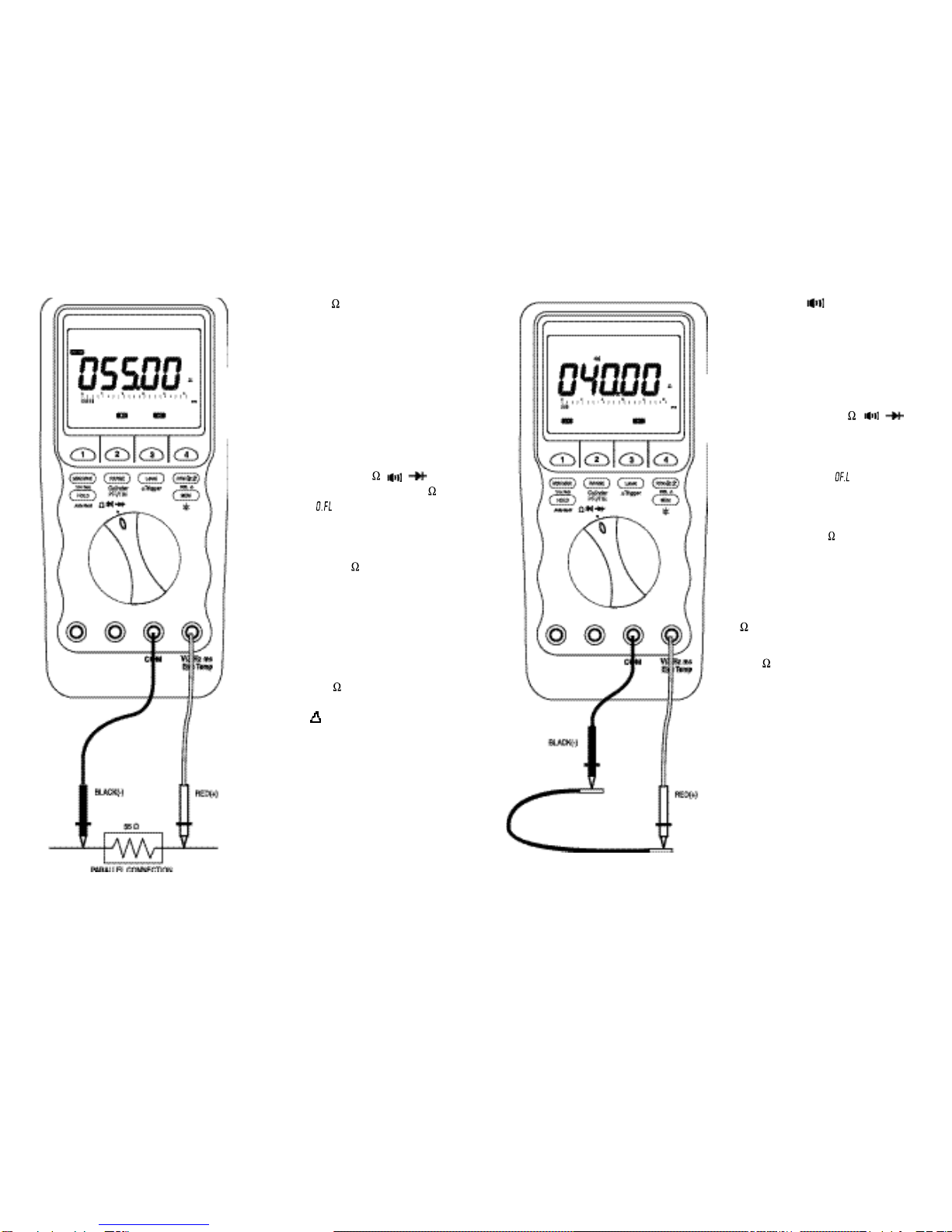
4-4. Resistance ( )
CAUTION
Tu rn off p ower and dischar ge all
capacitors on circuit to be tested
b efor e attem pting incircu it
resistance
measurements. Accurate
m easurem ent
i
s no t possible if
external o r r esidu a
l
voltage
is
present.
1. Set rotary selector
t
o
position. The me
t
er defaults at
function. is
dis played in the
primary display.
2. Insert black lead into COM terminal
and red lead into terminal.
3. Touch the test lead probes across
t
he resis
t
anc e or ci rcu it to be
tested.
NOTE: The res
i
stance in the test
leads can affect accuracy in
the 500 range.
S
hort
the
leads together and press the
REL
button to automatically
subt
r
act th e t est lead
resistance from
the measured
resistance.
4-5. Continuity ( )
CAUTION
Turn
th e pow er OF F on the t est
circuit. A beeper ton e do es not
necessarily mean zero resistance.
1. Set rotary selector to
position.
2. Pr ess menukey 2
to selec t
Continuity function. is displayed
in the primary display.
3. Insert black lead into COM terminal
and red lead into
terminal.
4. Touch the test lead probes across
the device being tested.
If the resistance of the device is below
70 , there is a continuous beep tone.
If the resistance of
the device
is more
than 70 , there is no beep tone.
This is us eful for c hec ki ng wiri ng
connections and operation of switches.
1918
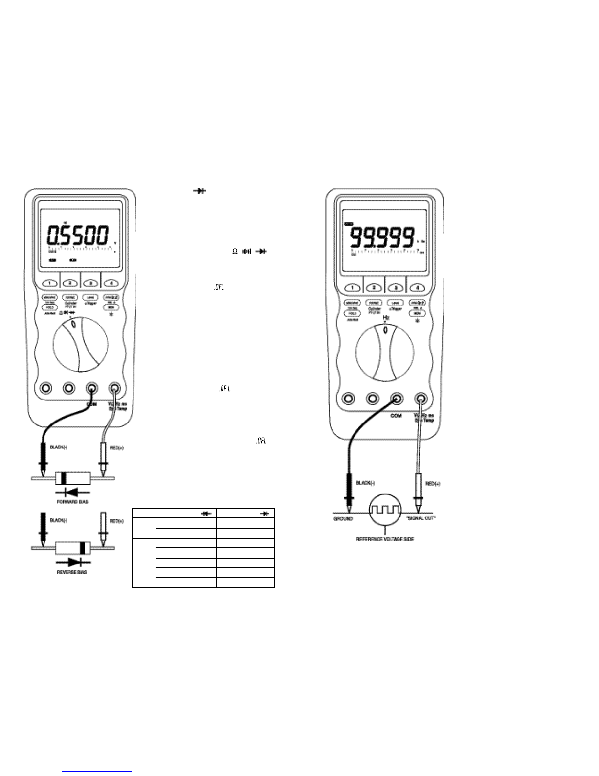
4-6. Diode ( ) Test
CAUTION
T urn th e pow er OFF on the test
circuit.
1. Set rotary selector to
position.
2. Press menukey 3
to select Diode
Test function. is
displayed in
the primary display.
3. Connect
t
he test
leads as shown
and observe the digital display.
Normal forward v oltage dr op
(forward biased) for a good silicon
diode is between 0.4 V to 0.9 V. A
reading higher than that indicates a
leak y d iode (def ec
t
i ve). A z ero
reading indicates a shorted diode
(defective). An
indicates an
open diode (defective).
4. Reverse the test leads connections
(reverse biased) across the diode.
5. The primary
display
shows if
the di ode
is good.
A
ny other
readi ngs i ndicate t he di ode is
resistive or shorted (defective).
Use the table below to determine if the
diode is Good or Bad.
4-7. Frequency
1. Set rotary selector to Hz position.
2. Insert black lead into COM terminal
and read lead into Hz terminal.
3. Touch black probe
t
o ground and
touch red probe to the “Signal out”
wire on the sensor.
FORWARD BIAS( )
0.4 to 0.9 V
OFL
OFL
1.0 to 3.0 V
0.4 to 0.9 V
OFL
0.0000 V
REVERSE BIAS( )
OFL
0.4 to 0.9 V
1.0 to 3.0 V
OFL
0.4 to 0.9 V
OFL
0.0000 V
DIODE
Good
Bad

2120
4-8. RPM (primary display)
WARNING
Be su
r
e the inductive pickup is in
t he te
r
m in als m a
r
ke d “ - RP M +”
w
hen m easu
r
in g RPM’s. If th e
p ickup is in th e
w
r
ong te
r
minal,
p e
r
son al inju
r
y o
r
m ete
r
dam ag e
may occur.
The ignition system can gene
r
ate a
potential shock haza
r
d. Ensu
r
e that
the engine is off befo
r
e connecting
or removing the inductive pickup.
1. Set rotary selector to RPM position.
The meter defaults at TRIG
(trigger) level.
2. Pr ess button to toggl e
between RPM for 4-stroke engine
and RPM for 2-stroke and DIS
engine.
3. Insert the Dual Banana Connector
into the RPM - and the RPM+ input
terminals as shown. Ensure the
plug with the Ground Tab goes into
the RPM- terminal.
4. Clamp the inductive pickup to a
spark plug wire with the arrow sign
facing the spark plug as shown.
Ens ure the pic kup jaws ar e
completely closed.
5.
Read RPM in the primary display.
NOTE:
4 t
r
igge
r
le
v
el
s
(TRI
G
TRIG
TRIG
TRI
G
) a
r
e
s
ele
c
table
b
y
p
r
e
s s
ing button
momentarily in this function.
Refer to 5-5 for more details.
4-9. Fuel Injection On Time
This function applies to both Port Fuel
Injectors (PFI) which operate with a
single On Time pulse and Throttle Body
Injectors (TBI) which operate with twin
pulses.
1. Set rotary selector to ms-Pulse,
Dwell, Duty position.
The meter default s at ms-Pul se
with –TRIG level in the PFI
mode. (“ ” appear s in the
secondary display for 1 second.)
Pr ess button to toggl e
between the PFI mode and the TBI
mode. (“ ”
appear s in the
secondary display for 1 second.)
4 trigger levels (–TRI
G
–TRIG –TRIG –TRIG
) ar e sel ectable by
pressing button momentarily
in this function.
2. Insert black lead into COM terminal
and red l ead into ms (-P uls e)
terminal.
3. Connect the test leads as shown
and read
O
n Time in the primary
display.
4. The fuel injection frequency can
be displayed in the second display
by pr ess ing t he butt on
momentarily twice.

( l
2322
4-10. Dwell
1. Set ro ta ry selec tor
to ms-Pulse,
Dwell, Duty position.
2. Press
menukey 3 to select Dwell
function.
The meter
defaul
t
s
at 4
cylinders ( ).
Pres s
Cy inder) button
momentar ily and repeatedly
to
selec t the required number o
f
cylinder and display the cylinder
setting in the second display.
3. Insert black lead into COM terminal
and red l ead into ms (-Pulse)
terminal.
4. Connec
t
the
test leads as shown
and read Dwel l angle in the
pr imary di splay . Adjus
t
tri gger
levels by pressing
button
momentarily, if necessary.
5. Press menukey 2 momentarily to
display
Dwell reading in terms of
percentage if required.
6. The frequency of
t
he same signal
sourc e can
be displayed in the
second display by pressing
t
he
button momentarily twice.
7. Adjust the dwell angle according to
the
procedures outlined in your
vehicle service manual.
NOTE: Recheck the
timing whenever
the
d well ang
l
e has been
adjusted.
4-11. Duty Cycle
1. Set rotary selector
to ms-Pulse,
Dwell, Duty position.
2. Press
menukey 2 to select Duty
function.
3. Insert black lead into COM terminal
and red l ead into ms (-P uls e)
terminal.
4. Connect the
test leads as shown
and read the duty cycle percentage
in the primary display.
Adjust trigger levels
by pressing
but
t
on momentari ly, if
necessary
5. Press menukey 1 or 3 momentarily
to dis play Duty Cycle reading in
ter ms o
f
ms (P uls e Wi dth) or
(Dwell) angle if required.
6. The
frequency of the
same signal
source
can be dis pl ayed in the
second display
by pressing the
button momentarily twice.
I
n mos
t
app lic ati ons ,
t
he negativ e
trigger slope is assigned to display the
percentage of time that the plunger is in
the c los ed posit ion (low du
t
y
cy cle)
during one duty cycle. The positive slop
is assigned to display the percentage of
time that the plunger
is in the open
posit ion. Ref er to the c ar’s servic e
manual to v erify slope ass igned t o
position for each component.
Press the (±Trigger) button for
more than 1 second to toggle between
t
he negative (-) slope and the positive
(+) slope, if required.

2524
4-12. Charging System Test
Charging system problems often
are
identified with a No-Start complaint.
The battery will
have discharged and
the starter won’t crank the engine. To
properly check the charging system,
the battery must be fully charged.
WARNING
Be sur e
the battery to a
l
ternator
connection and lead
connectio ns
are all secure, or damage may result.
1. Set rotary selector to Elec position.
The meter de
f
aults at Char ge
System Test function.
2. Insert black lead into COM terminal
and red lead into Elec terminal.
Battery Condition Test
1. Co nnec t
r ed lead probe to
the
alternator output.
2. Connec t bl ack l ead probe
t
o
ground.
3. With engine Off, turn the headlights
On low.
4. Read the secondar y
displ ay
to
check the condition
of the bat
t
ery.
Use the table below.
Alternator Charging Test
1.
Connect red lead probe to the alternator output.
2. Connect black lead probe to ground.
3. Start engine and run at 1000 - 2000 rpm.
4. Turn the headlights On low.
5. Allow the secondary display to stabilize.
6. Read the secondar y
displ ay
t
o chec k t he
alternator charging conditions.
A display “ ” or “ ” in the secondary display together with beep sound
indicates that the alternator charging system is in bad condition.
• No display in the secondary display : System normal.
• “ ” displayed : Suspect open field (current) or regulator.
•“ ” or “ ” displayed alternatively : Suspect bridge rectifier or grounded
stator winding.
• “ ” displayed : Suspect bridge rectifier or open stator winding.
NOTE: When the alternator and the associated rectifier diodes are in good
condition, the ripple voltage of the alternator output signal should be
less than 0.49 V AC (typical).
SECONDARY DISPLAY
(Battery Condition)
(Low Battery)
(No Charge)
(Good)
PRIMARY DISPLAY
< 11.399 V
11.400 ~ 13.299 V
13.300 ~ 15.599 V
• “ ” not displayed : Check wiring and battery leads.
• “ ” displayed : Good battery, proceed.
• “ ” and “ ” displayed : Low Battery, correct before proceeding.

2726
4-13. Ground Test
This function is designed to locate bad
grounds , volt age drops, intermi ttent
c onn ec tions, o r any sourc e
of high
res istanc e
in automoti ve electrical
circuits and grounds.
It provides
a very efficient check o
f
a
vehicle’s electrical system condition.
T his
t
es t work s by measuri ng the
voltage drop across any cable to which
it is connected. The amount of voltage
drop is displayed as “ ”, “ ”,
“ ”, and “ ” annunciators in the
secondary display.
1. Set rotary selector to Elec position.
2. Press menukey 2 to select Ground
Test function. “ ” is displayed in
the primary display and “ ” is
displayed in the secondary display.
3. Insert black lead into COM terminal
and red lead into Elec terminal.
4. Connect the two probes to the
cable being tested. A good
connection is indic ated by the
display of “ ” in the secondary
display.
5. Apply power to
t
he vehicle. The
condition of the cable between the
two probes is indicated by either
“ ”, “ ”, or “ ” in the
secondary display.
If either “
” or “
” is displayed
,
check the cable closely
for poor connections
between the two test leads.
Make certain all connectors are clean and secure.
NOTE: When checking ground connections
,
always clean
or scrape off the
area of the chassis where the ground lead is being connected. Dirt,
grease, and paint are insulators and will prevent the unit from making
a good
connection
.
If a ground connection is suspect, connect the
unit to the chassis as close as possible.
When
testing charging or
starting circuits from the battery, always make the first connection to
the battery
post, and not the battery connector. Corrosion on the
battery post and connector surfaces can be the source of the problem
very frequently.
SECONDARY DISPLAY
(Good)
(Suspect)
(Bad)
(Open)
PRIMARY DISPLAY (Amount of Voltage Drop)
< 0.1999 V
0.2000 ~ 0.3999 V
0.4000 ~ 1.9999 V
2.0000 V

4-14. O
2
Sensor
This is a very efficient method to check
and simulate O
2
Sensors.
This
test hooks
in parallel
with the O
2
Sensor circuit. The primary display will
s how O
2
Sensor voltage, while the
s ec ondary dis pl ay will sho w Cross
Counts (CC).
Cross Counts are the number of times
the readi ng crosses 0.45 V DC per
second.
Nominal CC is 1
t
o 3 for a good O
2
Sensor.
During this test, the secondary display
will indicate Full Lean, Lean, Rich, and
Full Rich respectively, according to the
measuri ng value of the O
2
Sensor
output, together with the corresponding
Cross Counts(.x).
2928
1. Set rotary selector to Elec position.
2. Press menukey 3 to select O
2
Sensor function.
“Lean” and “Rich” annunciators will be displayed on menu screen.
3. Insert black lead into COM terminal, red lead into Elec terminal, and green lead
into Signal terminal.
4. Unplug the O
2
Sensor connector.
5. Connect a jumper wire between the connector halves.
6. Connect red lead probe to the O
2
Sensor side of the jumper wire.
7. Connect black lead probe to ground.
8. Connect green lead probe to the ECM side of the jumper wire.
9. Press menukey 3 (Lean) or 4 (Rich) to send out a Lean or Rich signal for 5
seconds.
PRIMARY DISPLAY
< 0.29999 V
0.3000 ~ 0.4499 V
0.4500 ~ 0.5999 V
0.6000 V
SECONDARY DISPLAY
X(Full Lean)
X(Lean)
X(Rich)
X(Full Rich)
Also during this test the menukey 3 (Lean) or menukey 4 (Rich) might be pressed
to send out a rich command or a lean command for 5 seconds, which will make the
“Lean” or “Rich” annuncia
t
or on menu screen
f
lash depending upon which
was
commended. During this time the primary display will show the signal level that is at
the O
2
Sensor to see that the condition is being compensated for. The green lead is
required to be connected between the “Signal” terminal and the O
2
connector on the
ECM side.
NOTE: Signal out and CC may not funct
i
on properly on some Toyota O
2
Sensors.
3130
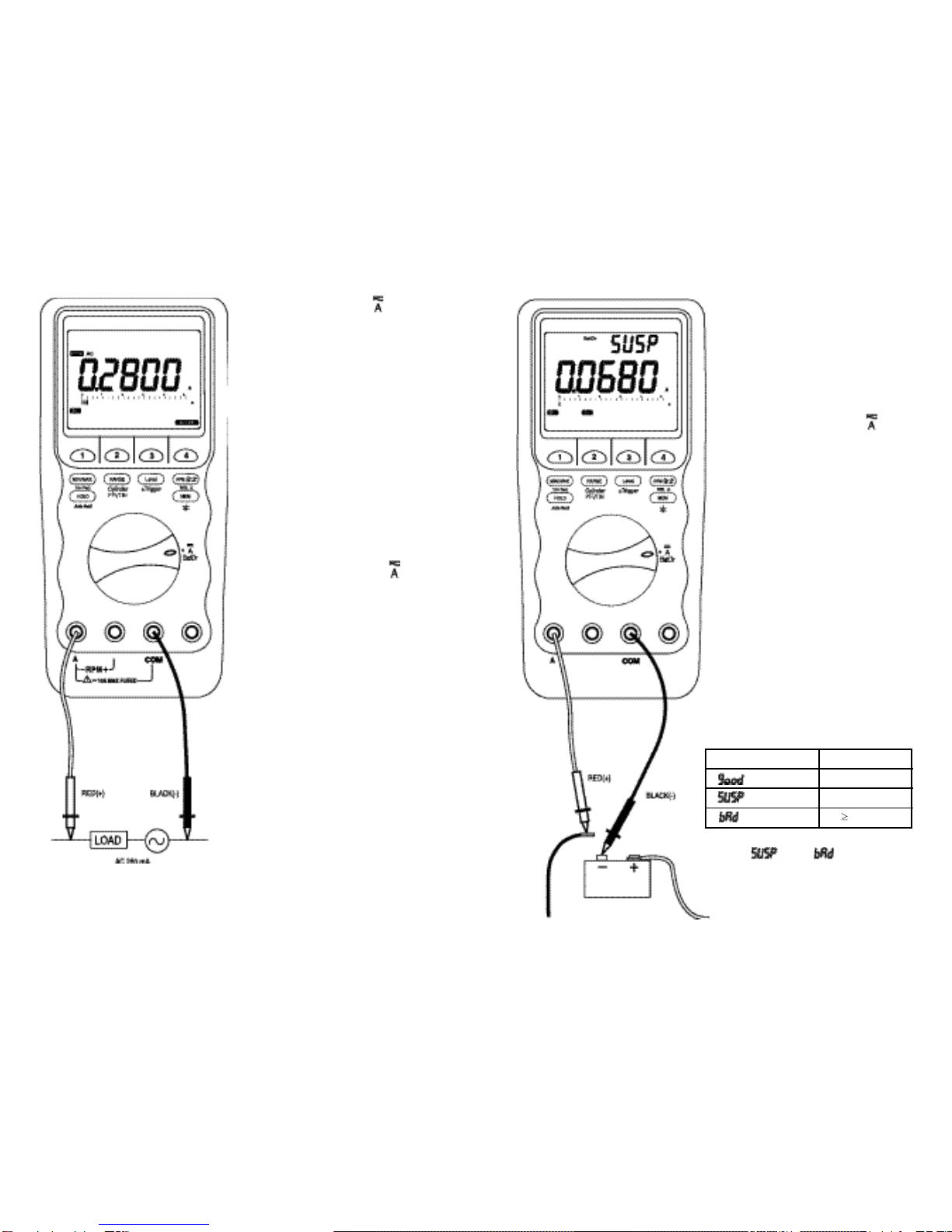
4-15. AC or DC Current ( )
WARNING
D o not measur e an y circuit
that
draws more than the
current rating
of the installed fuse. Replace the
defective fuse with a pr oper fuse
only. Failure to do this may result in
injury or damage to the meter. Do
not attempt current
measurements
where the o pen circuit voltage is
above 600 V.
For measuring circuits of more than
10 A
,
use voltage output cu rrent
c
l
amp adapters
compatible with
the
meter voltage functions.
1. Set rotary s elec tor t o BatDr
position. The meter defaults at DC
current.
2. Press menukey 2 to select AC.
3. Insert black lead into COM terminal
and red lead into A terminal
4. Connect red lead probe to the side
of the
circui
t
closes
t
to the power
source.
5. Connec t black lead
probe to the
side of the circuit closest to ground.
6. turn the power ON and test. DO
NOT crank the engine.
4- 16. Battery Drain Test
This f uncti on measur es
the c ar’s
battery current when it is turned off.
This test
will run continuously so
t
he
Au
t
o-Power-O ff feature wi ll be
automatically disabled in this mode.
1.
S
et rotary selec tor to
BatDr
position.
2. Press menukey 4 to select BatDr
test function.
3. Insert black lead into COM terminal
and read lead into A terminal.
4. Turn the ignition and accessories
Off.
5. Disconnect the negativ e battery
cable.
6. Touch red lead probe to the cable.
7. Touch blac k l ead pr obe to
t
he
negative battery post.
8. Observe the
s econdary display
(allowing up to 30 minutes).
If a “ ” or “ ” is displayed,
check fused and non-fused c
i
rcuit
for malfunction.
SECONDARY DISPLAY
(Low Drain)
(Marginal Drain)
(High Drain)
PRIMARY DISPLAY
< 0.0199 A
0.0200 ~ 0.0799 A
0.0800 A
3332
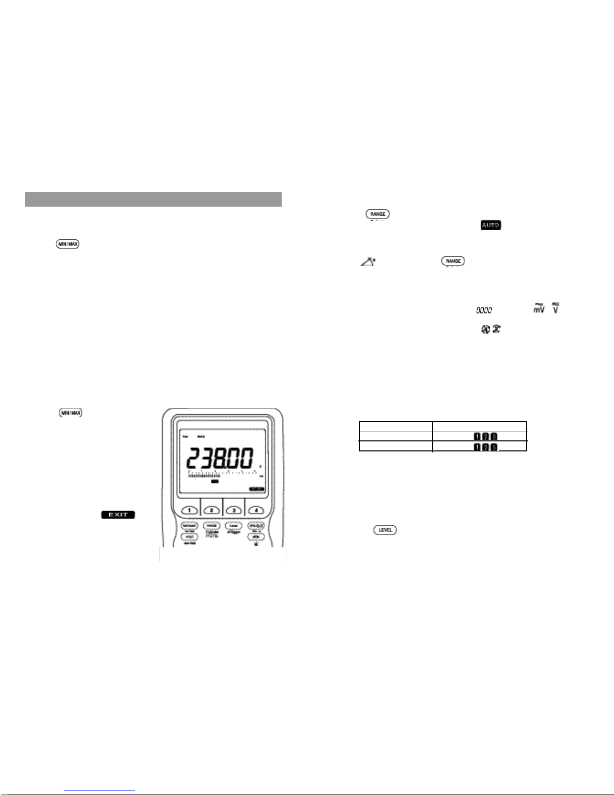
5-1. MIN/MAX Mode
Press the button momentarily to activate MIN/MAX(Record) mode with LCD
annunciators
MAX MIN
A
VG turned
on. Press this button
momentarily to read
throughout the maximum(MAX), Minimum(MIN), and Average(AVG) readings in the
primary display. Press this button for more than 1 second to exit MIN/MAX (Record)
mode.
With
t
he Autoranging MIN/MAX
(Record) mode, you can easily
t
rack intermittent
signals, capture turn on/ turn off surges, and monitor line voltage changes over a
much wider dynamic rage wi
t
h the best resolution. It surpasses manual ranging
recording which is apt to be overflowed or to have insufficient resolution. The meter
fea
t
ures
a fast sampling speed o
f
50 ms for MAX,
MIN and
AVG readings.
The
faster the sampling speed, the more accurate the measurements will be. The true
average (AVG) feature calcula
t
es all
readings con
t
inually
t
aken over time. The
Auto-Power-Off feature will be automatically disabled in this mode.
5-2. 1 ms Peak Mode
Press the (1 ms Peak) button
for more than 1 second
t
o activate 1
ms Peak mode with LCD annunciators
1 ms MAX MIN
turned on. The meter
defaults at 1 ms MAX (posi
t
ive
peak
value reading) mode.
Press the
menukey 2 momentarily to
select 1 ms MIN (negative peak value
reading) mode.
Press the menukey 4 ( on
menu screen) to exit 1 ms Peak mode.
With 1 ms Peak mode, transient signal
peak voltage as short as 1 ms can be
captured.
5. ADVANCED FEATURES
5-3. Manual and Auto Ranging
Press the button momentarily to select manual ranging, and the meter will
remain in the range it was with LCD annunciator
turned off.
Press this button
momentarily again to step
t
hrough
the ranges. Press this button for more than 1
second to resume autoranging.
In Dwell( ) function, press this (Cylinder) button momentarily to display
the cylinder setting on the secondary display. Default is
CL
4 (4 Cylinder). Press this
button momentarily again to select the number of cylinders from 1 through 12 (1, 2,
3, 4, 5, 6, 8, 10, and 12 cylinders) to match the engine under test.
NOTE: The secondary display defaults at rpm
i
n the
, , and Hz
function.
The selected cylinder setting or RPM setting is maintained until
the meter is turned off.
5-4. Trigger Level and +/- Trigger Slope Selection
This feature is available for RPM, Dwell, ms-Pulse, or Duty measurement function.
The meter is set at selected trigger level as power up default in individual function
as follows :
However, car signal levels under
t
est may
vary due to
aging of components,
abnormal conditions,
and each car manufacturer’s different design. Therefore
,
positive and
/
or
negative
4 selectable
trigger levels, which are carefully designed
and tested to cover all the extreme conditions, are available in these functions to
provide more flexibility to cope with your applications.
If your reading is unstable, select lower sensitivities (higher trigger level number) by
pressing the button momentarily. If your reading shows zero, select higher
sensitivities (lower trigger level number).
FUNCTION
RPM
Dwell, ms-Plulse, Duty
DEFAULT TRIGGER LEVEL
+ TRIG
– TRIG
3534
In some
cases, positive trigger levels may be required for measuring Dwell, ms-
Pulse, or Duty. Press the (±Trigger) button for more than 1 second to toggle
between positive (+) and negative (-) trigger level for the selected trigger level.
NOTE: Positive (+) trigger or negative (-) trigger is to identify whether the On
or
Off portion of
the s
i
gnal under test
is of measuring interest. For
example, if you get a reading of 10 % Duty Cycle in the Positive (+)
Trigger (On portion), you then will get a reading of 90 % Duty Cycle in
the Negative (-) Trigger (Off portion).
5-5. RPM Selection
In
the RPM
f
unction,
the meter de
f
aults to RPM
f
or
conventional 4-stroke engine
.
Press the button momentarily to toggle to RPM for 2-stroke or DIS
engine. And also in the , , or Hz function, press the button momentarily
to toggle between RPM and RPM setting for the dual display RPM function.
5-6. Relative Mode
Press the (REL ) button for more than 1 second to select the Relative
Zero ( ) mode with LCD annunciator turned on. This feature allows the user
to offset the measured value with a relative reference value.
Press the (REL ) button for more than 1 second to exit relative mode and
resume normal measurements.
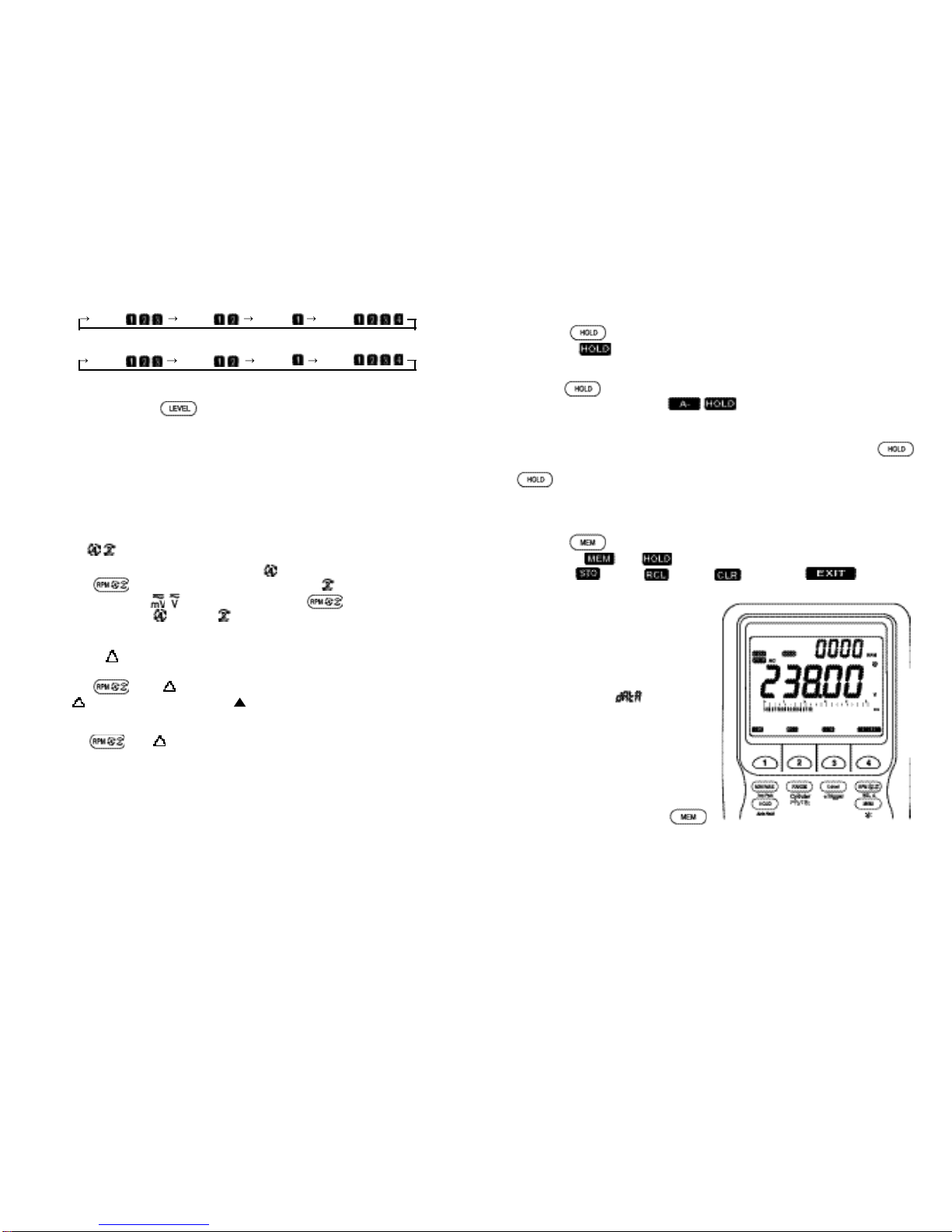
5-8. Memory (Data Store, Recall, & Clear) Mode
Press the
but
t
on momentarily to
activate the Memory
mode with LCD
annunciators
and
turned on. The menu screen shows four menu
selections : (Store), (Recall), (Clear), and (Exit).
Store : Press the menukey 1 to store
the
di splay in g data. The av ai lable
memory location number momentarily
shows in
t
he secondary
display
and
“
SA U E
” momentari ly s how s in the
primary display. If no memory location is
available, “
FULL
” and “
” momentarily
show in
the primary display and in the
secondary di splay respectively
and
nothing
is stored
,
when you
must clear
all the memory loca
t
ions by pressing
the Clear menukey to secure memory
locations. You can store up to 20 data.
You can exit the store mode by pressing
either the EXIT menukey or the
button momentarily.
5-7. Hold or Auto Hold
P
ress the
button
momentarily to activate the Hold func
t
ion with LCD
annunciator
turned on. Press
this
button momentarily again to exit Hold
function. This feature freezes the display for later view.
Press the
(Auto Hold) button for more than 1 second
to activate
the Auto Hold
func
t
ion with
LCD annunciators
turned on
.
This feature automatically
freezes the dis play and the
meter beeps when the measurement reading is
stabilized. The displayed value will be updated when a new measurement value is
stabilized. This mode is very use ful when it is impossible
f
or you to press the
button
or
see the me
t
er display while probing and
taking measurements. Press the
(Auto Hold) button for more than 1 second to exit Auto Hold function.
The 4 selectable trigger levels are cycled through as follows :
• RPM :
+
TRIG
+
TRIG
+
TRIG
+
TRIG
• Dwell, ms-Pulse, Duty
:
–
TR
I
G
–
TRIG
–
TRIG
–
TRIG
3736
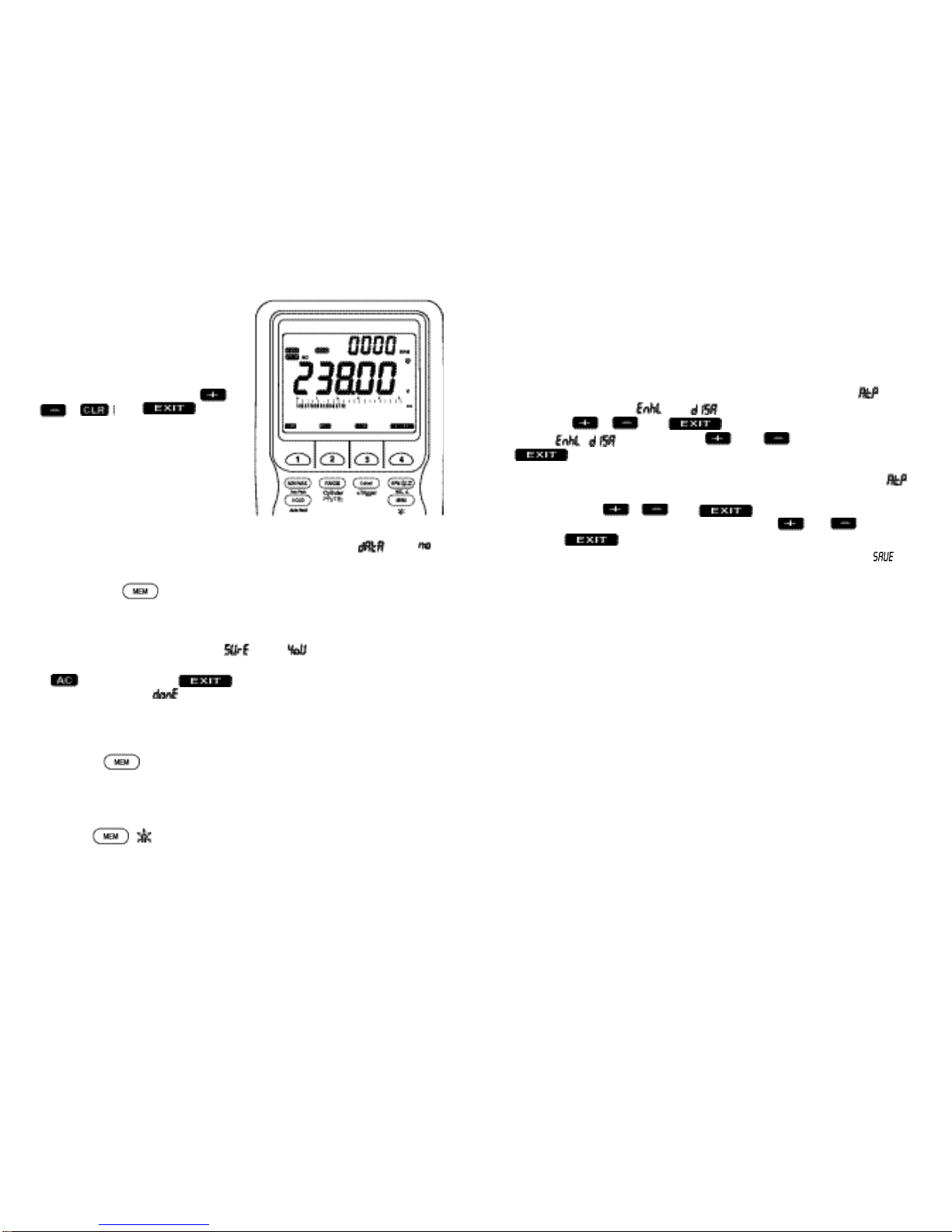
Clear
:Select Clear to clear all stored data in
t
he Store mode or only the data
stored at
the selected memory location in
t
he Recall
mode. In
t
he Store mode,
when you press the Clear menukey, “ ” and “ ” continuously show in the
primary display and in the secondary display respectively with two menu selections
; (ALL CLEAR) and turned on in the menu screen. When you
press the menukey 2, “ ” momentarily shows in the primary display and all the
stored data are erased. Press the EXIT menukey to exit the memory mode without
erasing any stored data.
EXIT :Select E
X
IT
t
o exit memory mode. You can also
exi
t
memory mode by
pressing the button momentarily or turning the rotary selector.
5-9. Backlight
Press the ( ) button for more than 1 second to toggle the backlight On
and Off.
The backlight wi ll also automatically be
Off 30
seconds a
f
ter eac h
activation to extend the battery life.
5-10. Auto-Power-Off
The meter automatically turns off after approximately 30 minutes of no activities to
extend battery life.
You can enable or disable the
A
uto-Power-Off mode. Turn the meter on while
pressing the menukey 4 to activate this feature, when the meter shows “ ” in the
Secondary display, and “ ” (or “ ”) in the primary display with three menu
selections ; , , and turned on in the menu screen. You can
toggle / by pressing the and menukeys. Press the
menukey to get into the next Setup.
The meter will display “ MIN
” annunciator at the upper lef
t
corner
of the LCD, “
”
in the secondary display, and a two digit number in the primary display with three
menu selections ; , , and turned on in the menu selection.
You can set up a new auto-power-off time by using the and menukeys.
Press the menukey to save the newly customized default values during
the entire Setup cycle. The meter will resume normal operation just after “ ” is
displayed in the primary display.
NOTE:
The newly customized default values in any Setup can be saved only
w
hen the entire Setup cycle
i
s ended. The
meter
displays “
SAUE
” at
the end of the entire Setup cycle only.
5-11. RS-232C Interface
The meter
provides an optically isolated
inter
f
ace port at the top
f
or
the data
communication. The RS70 optical adapter cable and the WS716 software disc are
required to connect the meter to the PC computer. These accessories are provided
to the end users as optional items.
Recall : Selec t Recall
t
o review the
stored data by pressing the menukey 2.
When you press the menukey 2, the last
memory location number used in the
prev ious memory op erat ion wil l
moment ari ly s how in
t
he s ec ondary
display with four menu selections ;
,
, , and turned
on in the menu screen. The
required
memory location can be s elected by
using the menukey 1 and the menukey
2, when the data stored at the selected
memory loc ati on wil l s how in t he
primary
display
.
In the Recal l mode
,
when you press the Clear menukey, the
data stored a
t
the recalled memory locat ion only is
erased. If
no stored
data is
available
in
the Recall mode, when
you press the Recall menukey, “
” and “ ”
momentarily show in the primary display and in the secondary display respectively
and nothing is retrieved. You can exit the Recall mode by pressing either the EXIT
menukey or the button momentarily
Table of contents


 Technical manual")


