Finevideo FV-DVP-704S User manual
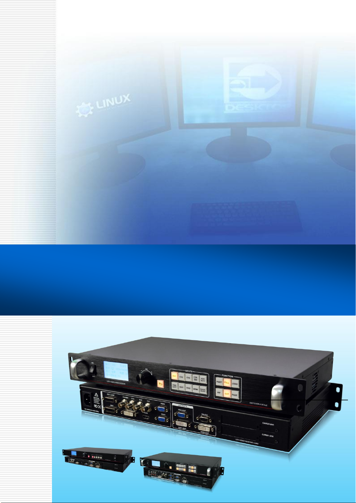
LED 视频处理器
LED Video Processor
Scale & Switcher
PIP POP Effect Preview
—— 中文 & English
用户手册
User’s Manual

18
Introduction
This manual contains information about how to use, install and configure the LED video processor, in
addition, also relates to knowledge LED video processor and LED video systems. Users are LED video
processor, please read this manual in detail.
About LED Video Processor
LED video processor is a mid-market seamless handover effects video processor, it supports high
definition digital input, analog HD input, analog SD input, audio input. With up to 8 video, three audio
inputs, as well as 3-way video in the same format, an audio output, and can achieve all channels
seamlessly switch audio and video synchronization.
The following lists the LED video processor supports audio and video input formats table:
DVI input VESA standard, the maximum 1920x1200 @ 60Hz
HDMI input 480i / p 676i / p 720p 1080i / p 8/10/12 bit color depth
VGA input VESA standard, the maximum 1920x1200 @ 60Hz
CVBS input PAL, NTSC, PAL-M / N, SECAM
Analog audio input analog audio signal
Output formats:
DVI output any resolution up to 2304x1152 @ 60Hz
VGA output any resolution up to 2304x1152 @ 60Hz
Custom resolution output
Analog audio output to any channel analog audio signals
Feature
Multi channel video input - LED Video Processor with 9 channel video input, of which 4 CVBS ,2
VGA,2 DVI 1 HDMI 1 3G-SDI inputs. Basically has covered the civil and industrial use requirements.
Video input switching all and can realize the fast cutting and fade switching effect.
Multi video and audio synchronous - LED Video Processor with 8 channel video input, 3 channel
audio switching. Each video can be any combination of the corresponding audio (including HDMI audio),
the corresponding relation between the set of audio and video, video channel automatic memory to
audio.
Seamless switching-LED Video Processor can also seamlessly switch between any channel
switching ,The time adjustable from 0 to 1.5 seconds. With a fade transition effect, switch the input
channel, so that the screen can be switched smoothly to the second screen. Using fast switching,
switching input channels, you can instantly switch the video output.
Full output resolution-LED Video Processor designed for users with useful output resolution, the widest
reach 2560 points, the highest of 1920 points, for a variety of dot matrix display. Up to 20 kinds of output
resolution for users to choose, and can be adjusted to point output.And it have custom resolution.
Pre-switching technology - pre-switching technology, is switching the input signal is switched to predict
in advance whether the input channel signal. This feature reduces the line is disconnected or may be due
to the case of no signal input to switch directly lead to errors, improve the success rate performances.

19
Support PIP - PIP technology unaltered state in the original image, the other input of the same or
different overlay images. LED Video Processor PIP function, not only can be adjusted overlay size,
location, borders, etc. You can also use this feature to achieve Picture outside Picture (POP),
dual-screen display.
One key black - black screen during a performance is an essential operation, during a performance, you
need to close the image output, you can use the black buttons for fast black.
Support Freeze - During playback, you may need to freeze the current picture together to achieve
"pause" screen. Freeze the screen, the operator can also change the current input selection or change
lines, etc., to avoid background operation affect performance results.
PART and FULL fast switching - LED Video Processor a simple and functional operation of the
interception part of the screen and full-screen operation, any one input channel can be independently set
different interception effect, and each channel is still able to seamlessly switch. Users can arbitrarily set
the current channel interception of part of the screen size and position, and the other channels remain
unchanged intercept method. When switching between channels most of its screen or full screen function
follow.
Preset -LED Video Processor user presets with 4 groups, each user can store all user default setup
parameters, use the LOAD preset shortcut keys you can quickly recall. Can achieve rapid field parameter
backup and recall function
Equal and unequal splicing - splicing is LED Video Processor important part, which can be achieved
equal splicing and unequal splicing, splicing on greatly satisfy users' needs. On multiple processors to
achieve frame synchronization, 0 delay, no tail and other technologies to enable smooth performance
perfect. Unequal spliced portion of the output is the same with the picture settings, the user can read the
following chapters for instructions.
30bit scaling technology - LED Video Processor using a dual-core image processing engine, a single
core can process 30 image scaling technology to achieve pixel output from 64 to 2560, while achieving
10 times the image to enlarge the output, ie, the maximum screen more than 25,600.
Brightness adjustment technology - LED Video Processor unique brightness adjustment function,
reduce the brightness solved after layering lost, so that more true color reproduction.
Saved directly technology - Saved directly technology to solve the user's settings and manually save
tedious process, that users of co-ordination or adjust parameters without the implementation of artificial
save operation, LED Video Processor user parameters automatically stored in EEPROM, even if the
power When turned on, the parameters before power remains in the device.
ACC &ACM image filtering - LED Video Processor using ACC and ACMimage filtering engine, handling
each color, nonlinear filtering effect of the lowest loss rate of the image, restore the color fidelity.
Support the upper RS232 interface control - can use computer to connect processor to use PC
software to set the output resolution, brightness, audio switch, switch signal source, etc.......
20
Panel
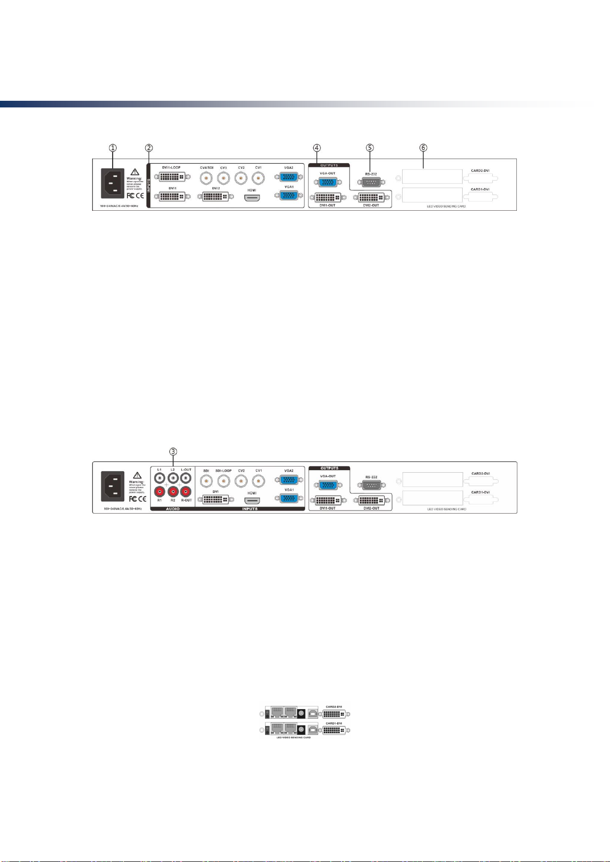
Rear Panel
Figure 1-Video processor rear panel
①AC power input - using IEC standard power cable video processor, the input power is 100-240 VAC,
50-60Hz.
②video input - processor can receive digital video signals, the analog video signal, a CVBS video
signal, the following criteria for each input interface.
● CV1, CV2, CV3 , CV4 CVBS video input, BNC connector, input video support PAL, PAL-M / N, NTSC,
SECAM formats. You can connect DVD players and camcorders.
● DVI1, DVI2 input, DVI-I standard interface, use the DVI-I or DVI-D cable, the video input format
supports VESA standard.
● HDMI HD video input, HDMI-A standard interface, support HDMI1.3 standard video inputs and VESA
standards. Used to connect desktop computers and HDMI high-definition player.
● VGA1, VGA2 video input, using the standard DB-25 connector, supports the VESAstandard video
input for connecting a desktop computer, laptop or other VGA video output device.
③Audio Interface - Processor with -channel analog audio inputs, one analog audio output.
Figure 2—Audio Interface
④video output - video output interface processor programming
● VGA output, using the standard DB-25 connector. DVI output interface with the output video format as
used to connect to a monitor.
● DVI output, using the DVI-I connector, the output video format is set by the processor, two DVI outputs
the same signal at the same time. Used to send the card or connected to the LED monitor.
⑤RS-232 - Serial communication connector for engineering testing, the device is programmed, PC
software control, communication baud rate is 115200bps.
⑥LED sending card - LED sending card installation location aside, you can install one or two to send
cards. When installed, the user can first open the back cover and the small bracket, mounting, internal
set aside four 5V power connector, four 2.0x4PIN connectors. After installing the plug 5V power supply.
Figure 3-LED sending card
21
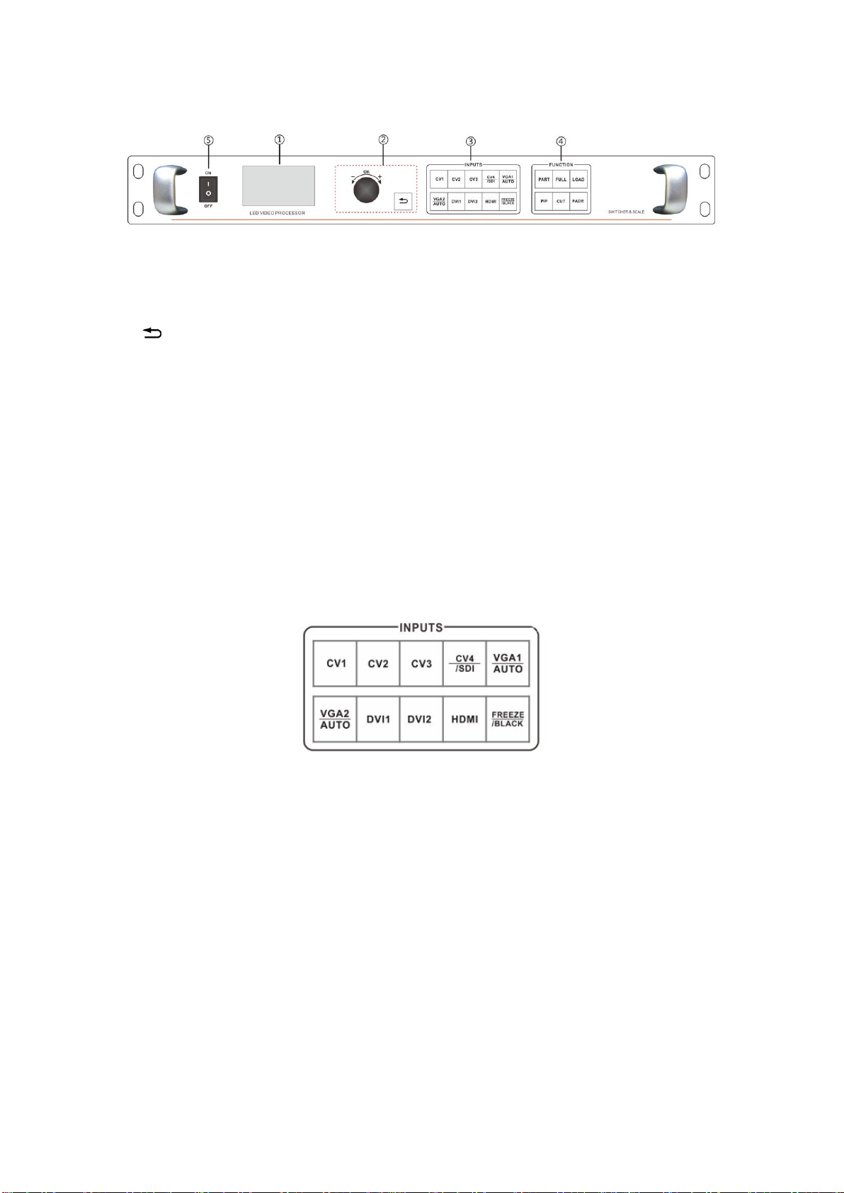
Front Panel
Figure 4-Front Panel
①LCD display - Display menu and current information.
②Menu operation buttons - Menu operation keypad with "Return key" ,Knob "confirm and adjust." The
following are included on each key.
● button, Exit key, or return to the previous menu.
● Knob , press the OK button to enter the menu or submenu key to confirm the function. Rotate around +
"plus" - "minus" operation, you can adjust the menu position or adjust the parameter value becomes
small.
③Input Selection - INPUT button in the region, including all of the input 8-channel switch button, the
test pattern, screen freeze, black screen, VGA automatic correction function buttons. button Indicators of
the button state in the region there are three kinds, namely:
The button lamp flashes slowly: Flashing interval of about one second, and has been in flashing,
indicating that the channel table when no signal switching.
Button light flashes quickly: When you press the button, the button indicating rapid flashing time is
about 0.3 seconds, indicates that the device is currently being tested and decodes the input video.
button indicator light: Indicates the current channel signals are connected properly or the current
function is active. Here is the Enter button on regional detailed description of the function buttons
Figure 5- Inputs
● CV1, CV2, CV3, CV4, CVBS video switching button.
● VGA1, VGA2 button, VGA input switching buttons and automatic correction button (AUTO function).
When the input channel for VGA1 or VGA2, repeatedly pressing VGA1 or VGA2 button VGA video
processor corrects the current channel, so that the screen output is normal. VGA channel AUTO function:
When the input channel for VGA1, and VGA1 have screen output, press VGA1 (AUTO) button, you can
recalibrate the current VGA1 signal. VGA2 button also has the same functionality and operation.
●DVI1, DVI2, HDMI bond, respectively, after the corresponding panel DVI1, DVI2, HDMI video inputs.
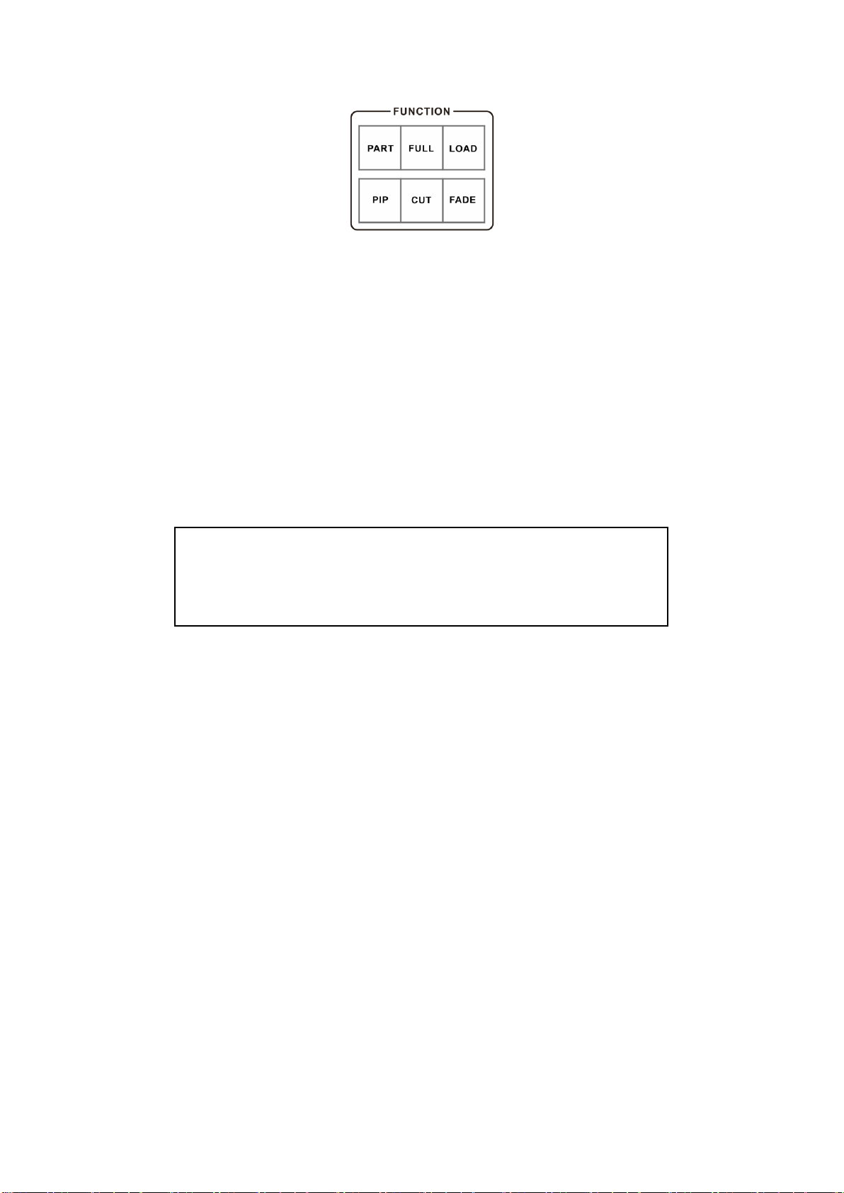
④Function button area - function button area contains a wide mode, preset call, PIP and transition
effects operating buttons can quickly achieve operating each function.
22
Figure 6—Function
●PART button: Part of the screen display mode, the user settings menu, good splicing interception
parameters section of the screen, press this button part of the screen to display the results. In the
following sections a detailed description of the operation.
●FULL button: A full screen mode, by default, all input channels are full-screen mode display mode.
When the user wants to set the mode from part to full-screen mode, simply press FULL button.
●LOAD button:To load preset scenes shortcuts. In the default state, press the Menu button to bring up a
list of preset scenes, together with the function button menu to bring up the preset scene. Save and recall
presets on the scene, in the following sections will be described in detail.
● PIP button : to turn on or off the PIP function buttons. User pre-set parameters PIP menu, use the PIP
shortcuts to quickly turn on or turn off the PIP function. About PIP's use, in the following sections in detail.
●CUT button, FADE button : Switching effect, CUT for fast cutting effect, FADE to fade transition effect.
Users when switching input channels can pre-select the transition effect is good press the Enter button.
Tip: When PIP (Picture in Picture) feature to work, you can not use PAT button
output test pattern; unusable FREEZE / BLACK button (or black screen freeze
function); function and can not be used CUT and FADE function (rapid transition
effects and Fade switching effect).

23
Menu System
Menu Structure
Figure 7 - Main Menu structure diagram
Operation menu
The main menu operation buttons “exist”,knob ,OK the man-machine interface for a 128x64 dot
matrix LCD screen.
Boot process equipment is as follows:
Figure 8- processor boot process and enter the main menu
Main menu
OUTPUT
Default menu
SPLICE
PIP
IMAGE
FUNC
SYSTEM
Function Description
Set the output resolution, precise adjustment of the
output resolution
Adjustment splice, equal splice or unequal or parts of
the image display
Set PIP size, position, the input source
Adjust image color, brightness, contrast, etc.
Setting the language, save or recall presets, BLACK
button functions
Set advanced features, information,Factory Reset
Power up
Display product
logo and model; the
button flashes three
times.
Default
menu
Main menu
3S
OK

24
Default menu
The default menu after the device starts, LCD screen interface, shown above, the input source, the input
source connected state, the input source is connected, the output resolution, mosaic mode, brightness
and output audio channels and other information, shows the processing the main parameters menu
system.
Figure 9 - Default menu
Main menu
The Main Menu is an important parameter adjustment user interface, almost all of the settings can be
done in the main menu. In the following sections there will be a detailed description of the operation and
settings for each function.
Figure12-Main menu
Setting and Operation
Language
Before using LED video processor, make sure the language you wish to use, if not, please follow the
operation to complete.
Default Menu → Main Menu → FUNC → Language
默认菜单→主菜单→功能→语言
Above is the menu operation path, use the button to enter the language settings menu you can select the
language.
Reset
When using LED video processor may not be confirmed because of errors or problems arise when
setting these parameters, you can enter the menu, make overall reset. Here is the process of resetting
the machine.
Default Menu → Main Menu → SYSTEM → Reset All→OK
After the reset, all user parameters back to factory state, users with caution.
In:HDMI No Sync
Out:1920x1080/60
Mode:Full Bright:50
PIP:VIDEO :HDMI
OUTPUT
T
SPLICE
PIP
IMAGE
FUNC
SYSTE
M

25
Output Resolution
Using different resolution display or LED screen, to achieve point-to-point output, it is necessary to set
the output resolution and the resolution of precise adjustment.
1. select a larger than screen resolution
Default Menu → Main Menu →OUTPUT → Output resolution→ confirmed
2. to fine-tune the output resolution
Default Menu → Main Menu →OUTPUT→
Switching Effect
Processor with two Switching Effect, Fast switching,fade in fade out and corresponding CUT or FADE
button.
CUT (Fast switching): when the input video switch, switch-free stay.
FADE (fade in fade out): when the input video switcher, both before and after the video image fusion,
the switching process smoother over.
The user can set to switch effects following two operations
1. press CUT or FADE button, press the button, the button indicator lights to alert the user of the current
state of transition effects.
2.to enter the menu settings
Default Menu → Main Menu → FUNC →Seamless
Fade time settings
Fade time can be controlled fade switching state of the time, the processor provides 0.5 seconds to 1.5
seconds fade time setting switch. Enter the menu settings as follows
Default Menu → Main Menu → FUNC →Fade Time
Black and Freeze settings
Black and screen freezes shared the FREEZE / BLACK button, in the menu system is
displayed as "BLACK button." It is set as follows
Default Menu → Main Menu →FUNC → BLACK FUNC
Once set up, simply press FREEZE / BLACK button to achieving a black screen or screen
freeze
Splicing applications
LED Video Processor has a powerful splicing, enabling hardware splicing 10x10 processors to
NOTE: When FREEZE / BLACK button role, you can not use the Enter button or the
PIP function.
Tip: You reset the output resolution, the system will reset all parameters menu
splicing to ensure data consistency. Accurate adjustment of the user is smaller than
the resolution of only the currently selected resolution when the resolution is equal
to the exact adjustment of the currently selected resolution, the horizontal and
vertical start value start value can not be adjusted.
Width
Height
H Start
V Start

26
achieve frame synchronization. There introduce it’s equal splicing and unequal
Equal Splicing
For example the following parameters of the LED screen wall
Device Name
Specification
Parameter
Other
LED unit
P3.9
Resolution 128x128
LED screen
20x16 unit
Resolution 2560x2048
LED sending card
XX
Support resolution
1280x1024
LED video processor
LED Video
Processor
Support resolution
2304x1152
NOTE: In calculating the LED video wall, try using the resolution calculation, in order
to avoid errors!
From the above parameters that can be divided into four equal portions LED screen area, a resolution of
1280x1024, respectively, these four named PANEL1, PANEL2, PANEL3, PANEL4, corresponding to the
processor P1, P2, P3, P4, send card named S1, S2, S3, S4. Below is a schematic connection
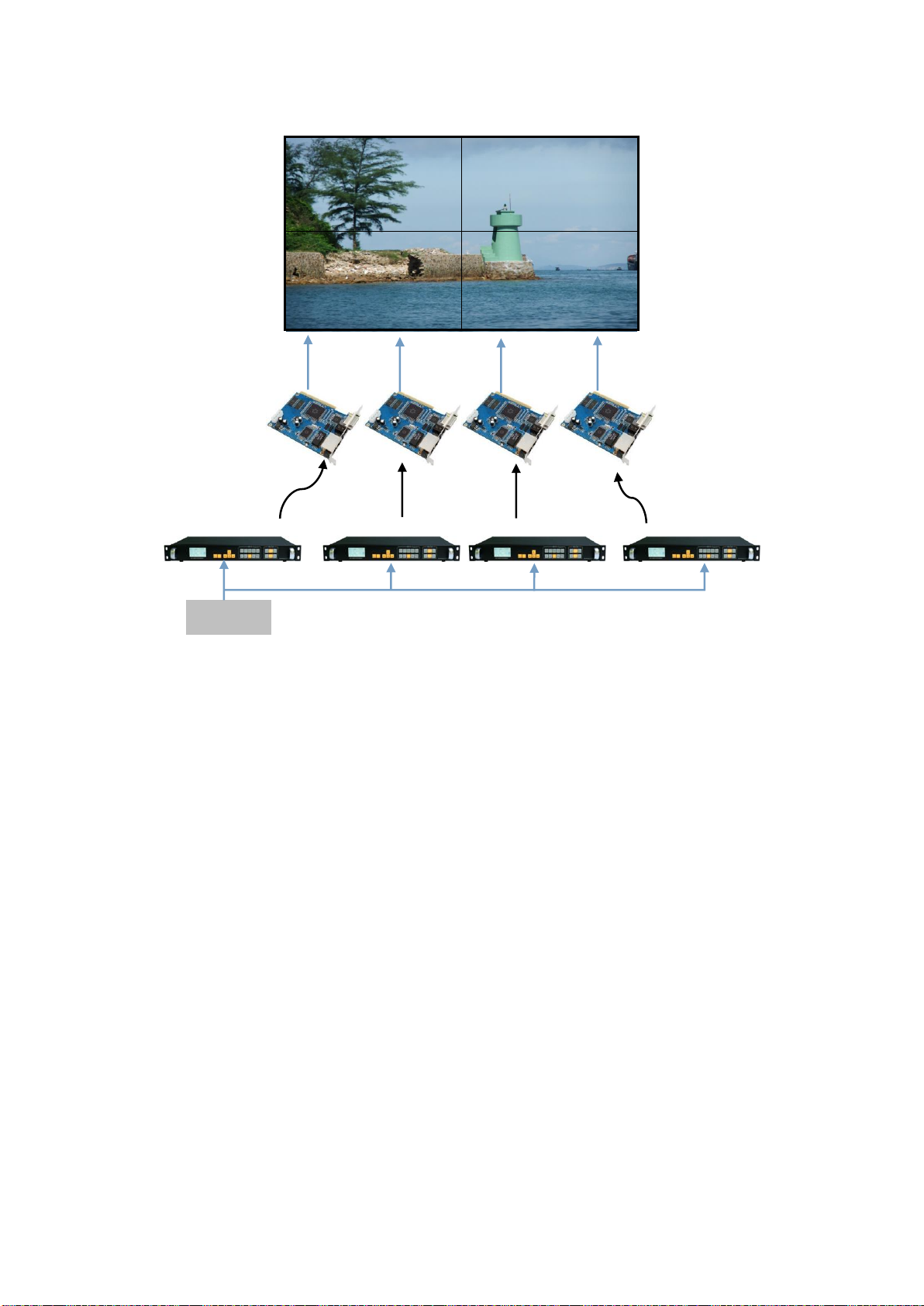
27
PANEL1
PANEL2
PANEL3
PANEL4
Figure 13-Equal Splicing
Steps:
1. Refer to Figure 13 for all connected devices.
2. LED screen software will adjust PANEL1 ~ PANEL4 respectively into four separate display area. (For
details, please refer to the relevant suppliers of LED system operation)
3. are provided P1 ~ P4 video processor parameters. Since the processor comes with 1280x1024 / 60
resolution, so no need to further fine-tune. All of the following parameters, only the splice location is not
the same.
Processor P1、P2、P3、P4:
1. Set the output resolution
Default Menu → Main Menu → OUTPUT →Resolution→1280x1024 60Hz
2. Set the splicing parameters
Default Menu → Main Menu →SPLICE→ MODE →V-Wall
Default Menu → Main Menu →SPLICE→ Pattern → Equal
Default Menu → Main Menu →SPLICE→V-Wall Sync → On
Default Menu → Main Menu →SPLICE→Parameters→H Units→2
Default Menu → Main Menu →SPLICE→Parameters→V Units→2
Processor P1:Splice position
Default Menu → Main Menu →SPLICE→Parameters→Position→1
Processor P2:Splice position
Default Menu → Main Menu →SPLICE→Parameters→Position→2
CAT5
CAT5
CAT5
CAT5
S1
S3
S4
S2
DVI-OUT
DVI-OUT
DVI-OUT
DVI-OUT
P1
P2
P3
P4
DVI-INPUT

28
Processor P3:Splice position
Default Menu → Main Menu →SPLICE→Parameters→Position→3
Processor P4:Splice position
Default Menu → Main Menu →SPLICE→Parameters→Position→4
Unequal Splicing
For example the following parameters of the LED screen wall
Device Name
Specification
Parameter
Other
LED unit
P3.9
Resolution 128x128
LED screen
21x7 unit
Resolution 2688x896
LED sending card
XX
Support resolution
2048x640
Two card connected
2048x1280
LED video
processor
LED Video
Processor
Support resolution
2304x1152
NOTE: In calculating the LED video wall, try using the resolution calculation,
in order to avoid errors!
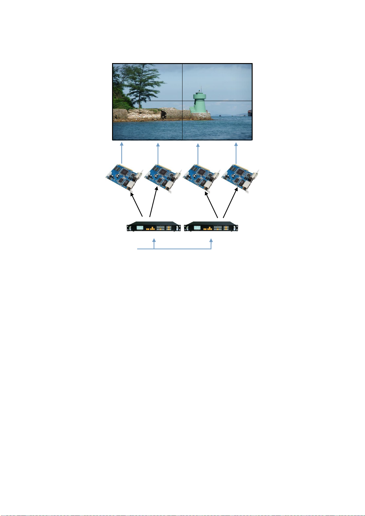
From the above parameters that can be divided into four LED screen unequal area, resolution
of 1408x512, 1280x512, 1408x384, 1280x384, respectively, these four named PANEL1,
PANEL3, sending cards corresponding S1, S2, corresponding to the video processor P1;
PANEL2, PANEL4, sending cards corresponding to S3, S4, corresponds to the video
processor P2. Below is a connection
NOTE: splicing synchronization open, cut and fade function is disable.
29
PANEL1
PANEL2
PANEL3
PANEL4
Figure 14-Unequal Splicing
Steps:
1.Refer to Figure 14 Connect all devices.
2.Sending card S1 and S2 cascade, S3 and S4 cascade. Respectively adjustment LED screen software
PANEL1 and PANEL3 into a complete display area, PANEL2 and PANEL4 set another full display area.
(For details, please refer to the relevant suppliers of LED system operation)
3.Are provided P1 ~ P2 video processor parameters.
Processor P1:
1.Setting resolution
Default Menu → Main Menu → OUTPUT →Resolution→1440x900 60Hz
Default Menu → Main Menu → OUTPUT→Width→1408
Default Menu → Main Menu → OUTPUT→Height→896
2. Setting splice
Default Menu → Main Menu →SPLICE→ MODE →V-Wall
Default Menu → Main Menu →SPLICE→ Pattern →Unequal
Default Menu → Main Menu →SPLICE→V-Wall Sync →On
Default Menu → Main Menu →SPLICE→Parameters→H Total→2688
Default Menu → Main Menu →SPLICE→Parameters→V Total→896
Default Menu → Main Menu →SPLICE→Parameters→H Start→0
Default Menu → Main Menu →SPLICE→Parameters→V Start→0
CAT5
CAT5
CAT5
CAT5
S1
S3
S4
S2
DVI-OUT
DVI-OUT
DVI -INPUT
P1
P2

30
Processor P2:
1.Setting resolution
Default Menu → Main Menu → OUTPUT →Resolution→1280x720 60Hz
Default Menu → Main Menu → OUTPUT→Width→1280
Default Menu → Main Menu → OUTPUT→Height→896
2. Setting splice
Default Menu → Main Menu →SPLICE→ MODE →V-Wall
Default Menu → Main Menu →SPLICE→ Pattern →Unequal
Default Menu → Main Menu →SPLICE→V-Wall Sync →On
Default Menu → Main Menu →SPLICE→Parameters→H Total→2688
Default Menu → Main Menu →SPLICE→Parameters→V Total→896
Default Menu → Main Menu →SPLICE→Parameters→H Start→1408
Default Menu → Main Menu →SPLICE→Parameters→V Start→0
Capture
Interception of part of the screen function is unequal extension splicing function. In actual use, may be
used to intercept the partial screen display, displays only a partial area of input channels. Such as the
Windows user interface, users simply DVI1 channel video playback window, the other input channel to
full screen. Processor provides users with two control keys, as shown below.
FULL PART
Figure15-Capture
Setting:
1.Select the channel you want to capture part of the screen, such as DVI1;
2. To enter the menu settings unequal splicing parameters (equivalent to capture part of the screen
parameters), the total pixel values and the start value is adjusted by visual inspection is completed.
Default Menu → Main Menu →SPLICE→ MODE →V-Wall
Default Menu → Main Menu →SPLICE→ Pattern →Unequal
Default Menu → Main Menu →SPLICE→V-Wall Sync → off
Default Menu → Main Menu →SPLICE→Parameters→H Total→4200
Default Menu → Main Menu →SPLICE→Parameters→V Total→3000
Default Menu → Main Menu →SPLICE→Parameters→H Start→0
Default Menu → Main Menu →SPLICE→Parameters→V Start→0
When switching the channel, as long as you want to advance channel selection FULL or PART effect
effect, the device will automatically save the current output for the input channel effects, that is, each
input channel display mode can be different.
NOTE: splicing synchronization open, cut and fade function disable.

31
PIP
PIP is the use of digital technology to display two programs on the same screen. That is the normal
viewing of the main screen, while the insertion of one or more sub-picture compressed in order to
appreciate the main screen while monitoring other channels. When operating in PIP mode mode, the
user must provide at least two of the input signal, and the PIP menu settings accordingly. PIP function
can be realized outside-picture effects, namely POP, PBP is a special application of the PIP.
Steps:
1.Turn on PIP, there are two ways to open, one by PIP button, the second is in the menu system
Default Menu → Main Menu → PIP →PIP mode→ PIP
2.Set the input source, the processor of the main channel and PIP channel, the same type of input source
can not be achieved PIP function, so users can refer to the following table PIP source conflict table.
Default Menu → Main Menu →PIP → PIP setup →Input
Table 3 - PIP Source conflict table
Main Chanel
CV1
CV2
VGA1
VGA2
DVI1
DVI2
HDMI
SDI
PIP
Chanel
CV1
√
×
√
√
√
√
√
√
CV2
×
√
√
√
√
√
√
√
VGA1
√
√
√
×
√
√
√
√
VGA2
√
√
×
√
√
√
√
√
DVI1
√
√
√
√
√
×
×
√
DVI2
√
√
√
√
×
√
×
√
HDMI
√
√
√
√
×
×
√
√
SDI
√
√
√
√
√
√
√
√
3.Size and position parameters, specific parameters set by the user, the user can also adjust the PIP
border transparency.
Default Menu → Main Menu → PIP→PIP setup→H Start
Default Menu → Main Menu → PIP→PIP setup→V Start
Default Menu → Main Menu → PIP→PIP setup→Width
Default Menu → Main Menu → PIP→PIP setup→Height
Keying
Keying is an extension of the PIP function, which is accomplished by the PIP channel input color image
minus the red, green, blue, black, and white colors to get results. Keying function can be used for some
simple effects processing and overlay subtitles. Easy setting operation, please refer to the setup.
For example, Figure 16A is a picture-channel playback of video for PPT, 16B is the main input channels,
16C is a matting effect.
NOTE: When the PIP is enabled, cut and fade function can not be used.

32
Figure 16A-PIP Chanel 16B-Main Chanel 16C-Output
Setting step:
Default Menu → Main Menu → PIP → PIP mode→Keying
Default Menu → Main Menu → PIP→Keying Setup→ Input→ DVI
Default Menu → Main Menu → PIP→Keying Setup→ Chroma Key→ Black
Preset
Preset is to facilitate users to use quickly recall commonly used in a variety of scenarios, reducing the
user when the operation is repeated complicated settings, improve work efficiency. Each contains a
preset mode signal channel mode, the display mode of various parameters, image quality settings.
Processor provides 4 preset save space, here to save and recall preset mode operation.
Save Preset
When the user adjust all the parameters, to enter to save the current preset
Default Menu → Main Menu → FUNC→ Preset→Save Mode → Preset [1] → confirm
In saving mode submenu have Preset [1] to Preset [4], four storage space, the user can choose. Storage
space is empty, the right of the status display for ☆, when the state has been saved had the right
argument appears as ★. Users can also cover save.
Recall Preset
Recall preset parameters have two operating modes, keyboard shortcuts and menu calls
1.Use LOAD button
In the default menu state, press the LOAD button to call up the menu to enter the preset scene. Use the
↑ and ↓ buttons to select the saved preset scene, press MENU button to confirm.
2.Setting in menu
Default Menu → Main Menu → FUNC→ Preset→Read Mode→Preset [1]→confirm
Pre-Switching
Pre-switching function can help users predict the source to be switched is connected properly, reduce
misuse live performances. Details as follows:
1. Into the pre-switching operation menu
When CUT or FADE button button lights up, repeatedly pressing the FADE button or CUT button, LCD
screen will prompt the user to enter the signal pre-switching state.
Figure 17-Pre-Switching
2.To select the input source to be switched, press FADE or CUT button or button switch.
In the pre-switching, press CV1 ~ SDI one button point, FADE or CUT button or key indicator flashes
CUR: DVI
PRE: VGA NoSync
TRANS FADE: 0.5S
Press EXIT to exit!

33
quickly, prompting the user to press the flashing CUT or FADE button switch.
Brightness and Contrast
Processor technology unique brightness, contrast adjustment, adjust color reproduction and high
brightness after the picture level without loss. Adjust the brightness, it is best to adjust the brightness and
contrast with, ensure perfect output effect. There are two ways to adjust the brightness
1.Use shortcut keys to adjust the brightness
In the default menu, press the Menu button control ← button, in order to reduce the brightness, press →
to increase the brightness. At this point the brightness values will change the default menu.
2.enter the image brightness and contrast settings menu
Default Menu → Main Menu→IMAGE→Brightness→50
Default Menu → Main Menu→IMAGE→Contrast→50
Key Lock
Key lock function for the user in a complex environment to avoid misuse or others inadvertently
Lock
Enter the system menu, enable key lock function
Default Menu → Main Menu→SYSTEM→Keypad Lock→on
Unlock
Press the FADE button last 2 second, processor automatically unlocked.
VGAAdjust
Under normal circumstances, switch to the VGAinput source, the processor will automatically correct
input source color, image size and position. If the processor does not automatically corrected
successfully, the user can manually correct implementation.
1.Use AUTO to adjust
When the input source is switched to the VGA input, VGA button is pressed again, the system will
self-correct input source.
2.Enter menu to adjust
Switching to the VGA input state, enter the menu
Default Menu → Main Menu→SYSTEM→VGA Setting→Auto Adjust→confirm
If automatic calibration is unsuccessful, you can try manually correct
Default Menu → Main Menu→SYSTEM→VGA Setting→H Position
Default Menu → Main Menu→SYSTEM→VGA Setting→V Position
Default Menu → Main Menu→SYSTEM→VGA Setting→H Clock
Default Menu → Main Menu→SYSTEM→VGA Setting→V Clock
Audio and video synchronization
NOTE: When no VGA signal input, the system prompts not correct.
NOTE: The same type of signal can not be pre-selected, otherwise it will
prompt "invalid channel!" Conflict pre-selected signal PIP input signal and
the same conflict, a detailed check list of the PIP conflict.
34
Video processor provides eight channels of video and 4 audio, there are three-way external audio input
and 1 channel audio input HDMI audio. So switching to a set of audio output. Follows
Set the current corresponding audio and video channels. In the default menu, use the ↑ and ↓ buttons to
toggle IN1 ~ IN3, HDMI, a total of 5 off the total state. Video channel and audio channel automatically
associated with the current set up after the next press CV1 ~ HDMI input buttons which the processor
automatically switches associated audio channels.
Specifications
DVI Inputs
Quantity
2
Connector
DVI-I
Signal Standard
DVI1.0,HDMI1.3 Backward compatible
Supported resolutions
VESA,PC to 1920x1200,HD to 1080p
HDMI Inputs
Quantity
1
Connector
HDMI-A
Signal Standard
HDMI1.3Backward compatible
Supported resolutions
VESA,PC to 1920x1200,HD to 1080p
VGA Inputs
Quantity
2
Connector
DB15
Signal Standard
R、G、B、Hsync、Vsync:0 to1Vpp±3dB (0.7V Video+0.3v Sync )
75 ohm black level:300mV Sync-tip:0V
Supported resolutions
VESA,PC to 1920x1200
※SDI Inputs(Optional)
Connector
1
Signal Standard
BNC
Supported resolutions
SD/HD/3G-SDI
Connector
1080p 60/50/30/25/24/25(PsF)/24(PsF)720p 60/50/25/24 1080i 1035i
625/525 line
CVBS(Video)Inputs
Quantity
2 x 2
Connector
BNC
Signal Standard
PAL/NTSC 1Vpp±3db (0.7V Video+0.3v Sync ) 75 ohm
Supported resolutions
480i,576i
※Audio Inputs
Quantity
1 x 2
Connector
RCA
Signal Standard
Analog audio
※Audio Output

35
Quantity
1
Connector
RCA
Signal Standard
Analog audio
DVI/VGA Outputs
Quantity
2 DVI、1VGA
Connector
DVI-I、DB15
Signal Standard
DVI:DVI1.0 VGA:VESA
Resolutions
1024×768@60Hz
1280×720@60Hz
1280×1024@60Hz
1440×900@60Hz
1600×1200@60Hz
1680×1050@60Hz
1920×1080@60Hz
1920×1200@60Hz
1024×1280@60Hz
1536×1536@60Hz
2048×640@60Hz
2048×1152@60Hz
2304×1152@60Hz
2560×816@60Hz
1280×720@50Hz
1920×1080@50Hz
1024×1920@60Hz
Whole machine
N.W
3.0kg
Size(mm)
Case size:(LWH)253×440×56
Packing size:LWH =515×110×355
Power Supply
100VAC –240VAC 50/60Hz
Maximum power
18W
Temperature
0°C~45°C
Storage humidity
10%~90%

36
DVI 视频输入
Table of contents
Popular Computer Hardware manuals by other brands

Motorola
Motorola DigitalDNA MPC180E user manual

Sierra Wireless
Sierra Wireless AirCard 595 user guide

Artaflex
Artaflex AWAC24UR user manual

Renesas
Renesas R0E510Y16LVB00 user manual

OWC
OWC Mercury FireWire 400 owner's manual

Pathway connectivity solutions
Pathway connectivity solutions PWINF DIN NFP manual


