- Check that the two jumpers J5 e J8 [E] are set to position "A"
5) 16 contacts x 7.5cm flat cable
11) Vocal Processor Owner’s Manual
12) WK4 Operating System Disk
10) Vocal Processor Demo Disk
Video Cable NTSC (Din to Rca)
9) Video Cable PAL (Din to Scart)
6) 10 contacts x 10cm flat cable
7) 2 contacts x 10cm cable
4) 9 contacts x 15cm flat cable
3) 34 contacts x 7.5cm flat cable
8) 4 screws (M3x8)
(Code 841009)
(Code 271200)
(Code 955991)
(Code 955990)
(Code 130317)
(Code 840823)
(Code 120003)
(Code 841025)
(Code 130428)
(Code 841004)
(Code 840204)
and that the jumper J1 [F] is set to position "A".
Audio/Video board NTSC
1) Audio/Video board PAL
2) 2 buffer modules
Part List:
(Code 761143)
(Code 761152)
(Code 761093)
NOTE:
modules are intalled.
position if the SIMM dram
modules are installed, on B
set on A position if the buffer
The jumper J1 [F] must be
KIT 970291 (PAL) - KIT 970292 (NTSC) - A/V Kit with Vocal Processor
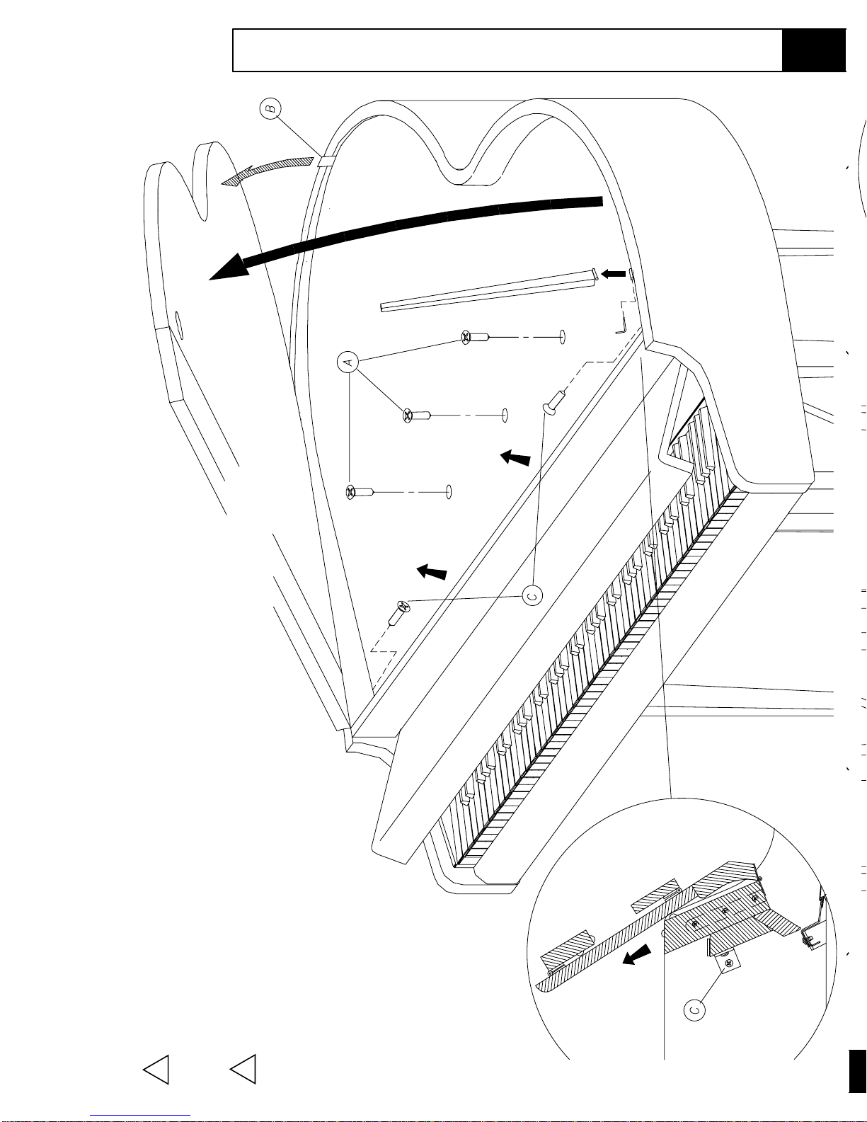
- Locate the CPU Board [A] and insert the buffer modules [2] into the connectors [H].
by means of the screw [8].
and to the CPU [A] and amplifier [D] boards.
- Fix the AUDIO/VIDEO Board [1] to the threaded locations of the support [B]
- Connect the cables [3-4-5-6-7] to the AUDIO/VIDEO Board [1]
- Connect the cable [3] to the CPU board.
ENGLISH
WK4, WK6 and WK6 Power Station
Model Instructions
Mounting
Mounting Instructions M-9
Leave the jumper J2 on its
position.
NOTE: for WK6 and WK6 Power Station use the operating system disk supplied with the keyboard.
- Check that the two jumpers J5 e J8 [E] are set to position "A"
5) 16 contacts x 7.5cm flat cable
11) Vocal Processor Owner’s Manual
12) WK4 Operating System Disk
10) Vocal Processor Demo Disk
Video Cable NTSC (Din to Rca)
9) Video Cable PAL (Din to Scart)
6) 10 contacts x 10cm flat cable
7) 2 contacts x 10cm cable
4) 9 contacts x 15cm flat cable
3) 34 contacts x 7.5cm flat cable
8) 4 screws (M3x8)
(Code 841009)
(Code 271200)
(Code 955991)
(Code 955990)
(Code 130317)
(Code 840823)
(Code 120003)
(Code 841025)
(Code 130428)
(Code 841004)
(Code 840204)
and that the jumper J1 [F] is set to position "A".
Audio/Video board NTSC
1) Audio/Video board PAL
2) 2 buffer modules
Part List: (Code 761143)
(Code 761152)
(Code 761093)
NOTE:
modules are intalled.
position if the SIMM dram
modules are installed, on B
set on A position if the buffer
The jumper J1 [F] must be
KIT 970291 (PAL) - KIT 970292 (NTSC) - A/V Kit with Vocal Processor
- Locate the CPU Board [A] and insert the buffer modules [2] into the connectors [H].
by means of the screw [8].
and to the CPU [A] and amplifier [D] boards.
- Fix the AUDIO/VIDEO Board [1] to the threaded locations of the support [B]
- Connect the cables [3-4-5-6-7] to the AUDIO/VIDEO Board [1]
- Connect the cable [3] to the CPU board.
ENGLISH
WK4, WK6 and WK6 Power Station
Model Instructions
Mounting
Mounting Instructions M-9
Leave the jumper J2 on its
position.
NOTE: for WK6 and WK6 Power Station use the operating system disk supplied with the keyboard.