Fire Burglary Instruments XL560 User manual

Fire Burghy
Instruments, Inc, II ’
INSTALLA’TION
XL5601561
INSTRUCTIONS
I)
50 Engineers Road, Hauppauge. New York 11788
7
5wireremote/master
keypad
intro?
The X1560/561 is a 5 wire remote/master keypad to be used exclusively with
the X11213. There are six functions available, that are all field programmable
at the XL560 keypad: arm/disarm, bypass zones 1, 2, & 3, auxiliary arming and
panic. (Auxiliary arming can be used to permit temporary arming and disarming
of control panel, as desired by customer, maid, guests, etc.). Five LED’s are
mounted on the keypad to annunciate arm/disarm, loop status and the three
bypasses. Up to three XL560 keypads may be used with each X1561. The Red
LED will be ON when the XL1213 is armed and blinking for alarm memory. The
Green Loop Status LED will be ON when all the Protective Loops are good, and
OFF if any loop is violated while the control is unarmed. The bypass LED’s will
be ON when a zone is bypassed. ‘,
FIRE BURGLARY INSTRUMENTS, IN
HAUPPAUGE. NEW YORK
ISSUE A MARCH ‘83

Step1
MODEL
554
10 PIN RIUBON . . . USED
ONLY IF
XL1213 BOARD IS PRIOR TO REVISION
A
I I 4
Pl
I I
(TERMINALS)
ORANGE STRIPE -
WHITE JUMPER
ESS CODE
PINS
20 PIN RIBBON CO
.
WHITE TERMINALS
XL561
Mount the XL561 master inside the XL1213 box and make the following wire
connections between the XL560 and the X1561.
XL560 Wires ’ XL561 Terminals i XL1213 Terminal
Red 5 *
+ .‘%
Black 6
Orange l, , 7 I :
Yellow :_ 8 )
White I
L, 9 Term. 10
Silent Panic
* If panic is desired cut the White jumpers on the XL560 & XL561 and
DO NOT use the Number 2 in any of the codes to be programmed.
Panic is activated by simultaneously depressing the # and * buttons
momentarily.
Step2
Plug in the Model 553 20 pin ribbon connector between the XL561 and the
XL1213 as shown. (XL1213 boar d
s prior to Rev A require 20 pin and
10 pin ribbon connectors).
ProgrammingInformation
Step3
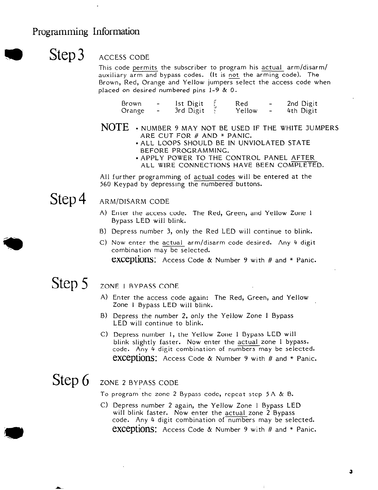
ACCESS CODE
This code permits the subscriber to program his actual arm/disarm/
auxiliary arm and bypass codes. (It is not the arming code). The
Brown, Red, Orange and Yellow jumpers select the access code when
placed on desired numbered pins 1-9 & 0.
Brown - 1st Digit f Red - 2nd Digit
Orange - 3rd Digit !’ Yellow - 4th Digit
NOTE
. NUMBER 9 MAY NOT BE USED IF THE WHITE JUMPERS
ARE CUT FOR # AND * PANIC.
l
ALL LOOPS SHOULD BE IN UNVIOLATED STATE
BEFORE PROGRAMMING.
. APPLY POWER TO THE CONTROL PANEL AFTER
ALL WIRE CONNECTIONS HAVE BEEN COMPLETED.
All further programming of actual codes will be entered at the
560 Keypad by depressing the numbered buttons.
Step4
ARM/DISARM CODE
A) Enter the access code. The Red, Green, and Yellow Zone 1
Bypass LED will blink.
B) Depress number 3, only the Red LED will continue to blink.
C) Now enter the actual arm/disarm code desired. Any 4 digit
combination may be selected.
eXCeptiOnS: Access Code & Number 9 with I/ and * Panic.
Step5
ZONE 1 BYPASS CODE
A)
B)
Cl
Enter the access code again: The Red, Green, and Yellow
Zone 1 Bypass LED will blink.
Depress the number 2, only the Yellow Zone 1 Bypass
LED will continue to blink.
Depress number 1, the Yellow Zone 1 Bypass LED will
blink slightly faster. Now enter the actual zone 1 bypass.
code. Any 4 digit combination of numbers may be selected.
eXCeptiOnS: Access Code & Number 9 with # and * Panic.
Step6
ZONE 2 BYPASS CODE
To program the zone 2 Bypass code, repeat step 5A & B.
C> Depress number 2 again, the Yellow Zone 1 Bypass LED
will blink faster. Now enter the actual zone 2 Bypass
code. Any 4 digit combination of numbers may be selected.
exceptions:
Access Code & Number 9 with # and * Panic.
3

StepI
ZONE 3 BYPASS CODE
To program the zone 3 Bypass code, repeat Step 5 A & B.
C) Depress number 3, the Yellow Zone 1 Bypass will blink
very fast. Now enter the actual zone 3 bypass code. Any 4
digit combination of numbers may be selected.
eXCeptiOIlS: Access Code & Number 9 with # and * Panic.
Step8
AUXILIARY ARM/DISARM CODE
To program the auxiliary arm/disarm code, repeat Step 5 A
8) Depress number 1, only the Green loop status “Ready” LED
will continue to blink.
C) Now enter the actual auxiliary arm/disarm code if needed.
Any 4 digit combination of numbers may be selected.
eXCeptionS: Access Code & Number 9 with # and * Panic.
I
IF ANY OF THESE FUNCTIONS ARE NOT DESIRED, SIMPLY DO NOT
PROGRAM THE CODE FOR THAT FUNCTION. ONLY PROGRAM IN THE
NOTE
CODES FOR THE FUNCTIONS DESIRED.
IF ANY OF THE CODES NEED TO BE CHANGED, ONLY THAT CODE MUST
BE REPROGRAMMED, THE OTHER CODES WILL REMAIN AS PREVIOUSLY
PROGRAMMED. I
step9
Programming should now be completed. Operate all functions.
If any fail to operate, repeat necessary programming steps.
f
ADDITIONAL NOTES
4
q
FIREBURGLARYINSTRUMENTSINC.
c r
INC
This manual suits for next models
2
Table of contents
Other Fire Burglary Instruments Keypad manuals


