Warranty and Installation Information:
The Montigo warranty will be voided by, and Montigo disclaims any
responsibility for, the following actions:
Modification of the fireplace and/or components including vent
assembly or glass doors.
Use of any component part not manufactured or approved by
Montigo in combination with this Montigo fireplace system.
Installation other than as instructed in this manual.
Consult your local Gas Inspection Branch on installation requirements
for factory-built gas fireplaces. Installation & repairs should be done by
a qualified contractor.
Installations in Canada must conform to the current CAN/CGA
B-149.1 and .2 Gas Installation Code and local regulations. This ap-
pliance must be electrically grounded in accordance with CSA C22.1
Canadian Electrical Code Part 1 and/or Local Codes. See Appendix A
for installation within the State of Massachusetts.
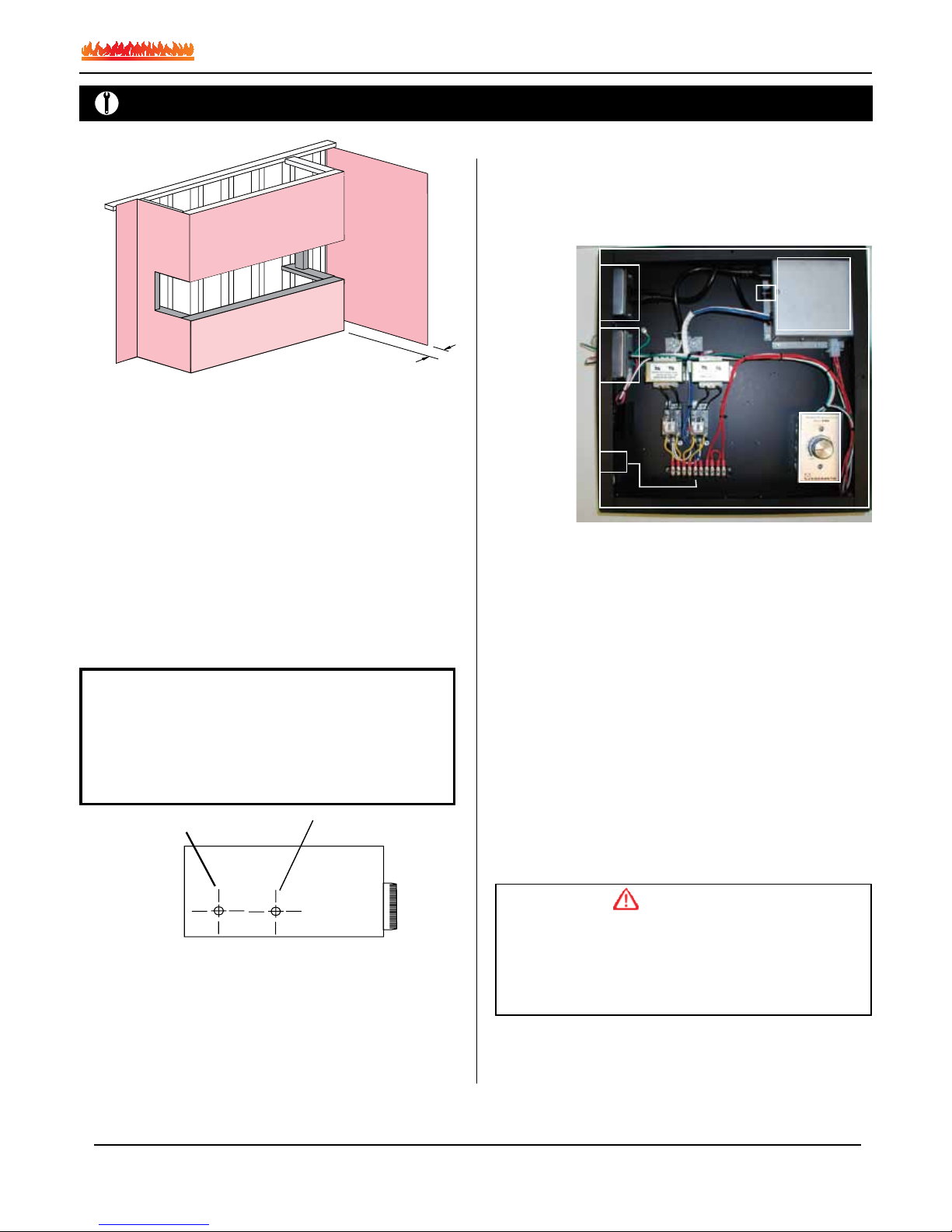
System Installation / Sequence
of Operation
Follow these instructions to ensure the safe and
ecient operation of your Custom replace.
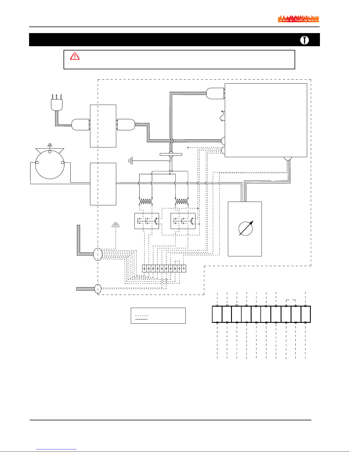
All connections are to be made Per. the instructions within this
Instruction Guide.
Ensure the wall switch is turned to the “OFF” position.
Energize the electrical control panel. The Power Vent motor should
run for three (3) minutes then automatically switch off.
Turn the wall switch “ON”.
The power vent motor will start to run and develop a negative
pressure in the vent above the gas flue outlet. (This negative
pressure is monitored by a pressure switch located in the bottom
of the fireplace). When this negative pressure exceeds 0.02" WC,
the switch will close the connection on terminal strip #9 and #10
located in the electrical panel.
This will power up both relays supplying 24 Volts to the Honeywell
control valves located in the bottom of the fireplace. The glow pug
on the pilot system will ignite the pilots, and the sensor will identify
the presence of a pilot flame and turn the gas valve to fully open
position.
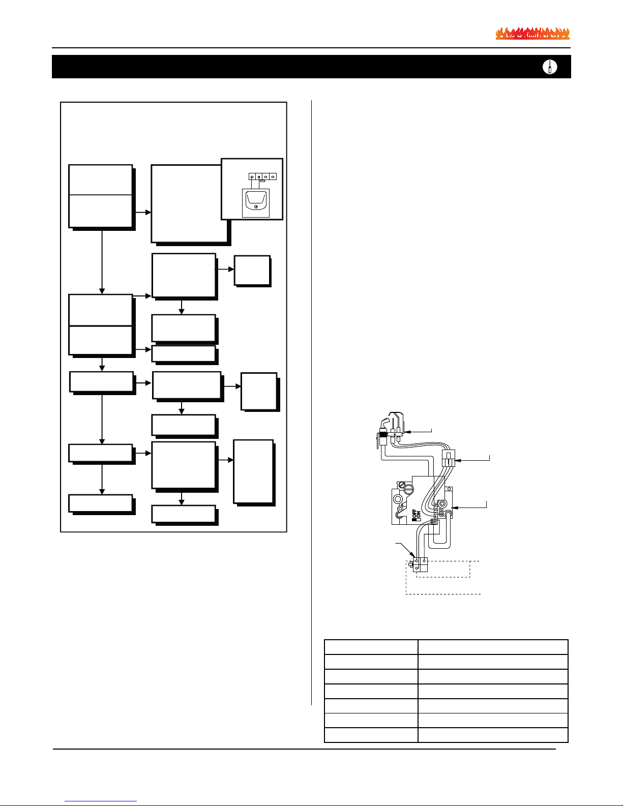
In the event that a pilot can not be established the electronic
monitoring system in the smart valve will repeat this process three
times. If the system is not successful in the third attempt the valve
will lock out.
To reset the system turn the wall switch “off”, and then switch back
“ON” to repeat this sequence.
Should the system NOT ignite, read the trouble shooting section
for additional information.
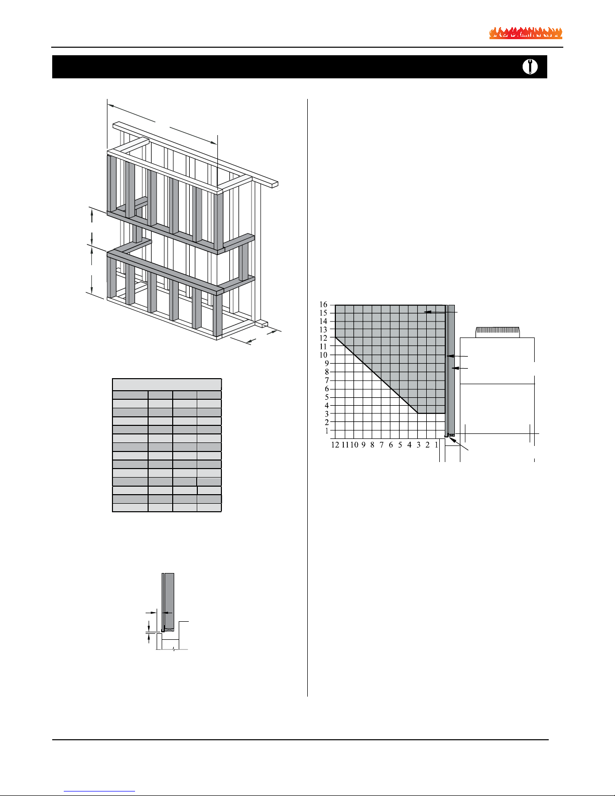
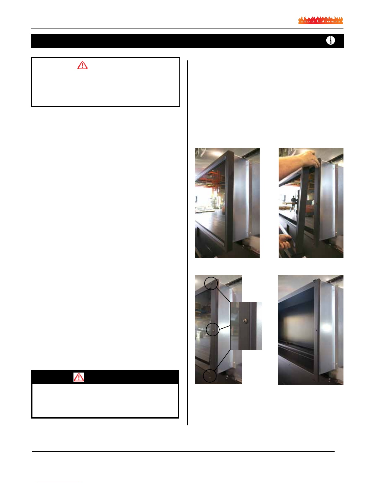
Installing The Fireplace
To install the fireplace:
The C-View fireplace system is an engineered fireplace system, and
will require you to provide the correct vent run and air supply informa-
tion to the Engineering staff of Montigo. Note: The C-View fireplace
may be purchased as an open-front fireplace (no glass door), provid-
ing the the combustion air supply has been considered for the safe
operation of the fireplace.
Please consult with Montigo on the method which the volume of com-
bustion air supply is to be delivered to the model of choice. C-View
fireplaces with a glass front may also take the combustion air from the
interior of the structure, and will be required to meet the requirements
as one without a glass front. C-View fireplaces which use air from the
exterior of the structure fall into the category of a ‘sealed combustion
type appliance’.
Fresh Air Supply:
Connect all of the fresh air supply for this fireplace to the lower vent
connections assuring no reduction or restriction to the air supply
occurs, even due to unexpected circumstances. Please consider auto-
mated dampers, particularly on the intake air supply in cold climates.
This is especialy important when the intake air is introduced from the
top down. Cold air has the tendency to settle to the lowest point in the
vent system.
For extra long air supply runs, Montigo will recommend an increase in
vent diameter. When changing the air supply from several incoming air
connections to one vent, consult this information with your contact at
Montigo. To ensure adequate operation of the vent system ensure the
size of the one vent is not less than the total sum of vents that you are
connecting to.
Flue Gas vent run:
The C-View fireplace system may be installed with any certified UL
or ULC B-Vent. All the clearances to this B-Vent must be equivalent
to the manufacture’s specifications as outlined in the installation/
operation manual. The size of this B-vent is specified in the approval
process and cannot be reduced unless Montigo has re-evaluated your
system. If authorized to reduce your vent size you will be issued new
shop drawings reflecting the new vent connection size and specifica-
tions.
The vent system may be installed vertically or horizontally, to any
length, and may have numerous elbows. (Quantity of elbows as sup-
plied to Montigo). The vent run may also be lower than the fireplace
flue gas outlet, or have a portion that is lower than the main vent run,
as long as Montigo has reviewed and engineered the entire system.
Montigo will then re-evaluate this information and size the Power Vent
to the vent restriction, and compensate for the pressure drop.
Power Vent:
Montigo manufactures a variety of Power vent modules as large as
5KWatts. The Power vent is commonly placed either horizontally or
vertically at the end of the B-Vent run. However, we have an in-line
vent module available. This Inline Power vent is for installations where
an exterior module isn’t visually attractive, or permitted.
Also, In-line Power vents are more complex to install, primarily due to
the positive pressure in the vent system after the Power vent module.
Therefore this vent run after the Power vent module must be air-tight
due too the concern gas by-products may leak from the vent into the
structure.
All Power vent modules create a negative pressure before the module
and leaks in the vent draw air from the building and will not create a
safety hazard.
Important:
All dimensions, and design specifications are
subject to approval upon quotation of fire-
place and associated equipment.
Installation
Page 4