Fischer Amps In Ear Amp 8 User manual
1
FISCHER AMPS
Manual
In Ear Amp 8
[Art. No. 001123]
Dear customer:
You have decided to buy a Fischer Amps product. Thank you.
Please read this manual carefully prior to the first use, you will get important information for
use and safety of the unit. These safety and operating instructions should be retained for
future reference.
Should you have further questions, please do not hesitate to contact FISCHER AMPS.
Product Description:
The perfect solution to provide up to eight musicians with an in ear mix. The half rack-space In Ear Amp 8 with
eight XLR outputs is based on the Fischer Amps In Ear Amp 2. Musicians can control their volume individually
with Fischer Amps Mini Body Packs with XLR input [Art. No. 001125]. The In Ear Amp 8 allows short cable
routes on stage and cabling with standard microphone cables. Thanks to the Class A MOSFET amplifier with
switchable output power, the unit can be used with high-impedance headphones as well as with low-impedance
in ear earphones. The XLR inputs have parallel XLR outputs so that the signals can be looped-through to the
next In Ear Amp. Using the In Ear Amp 8 is a simple but effective way to provide a stereo mix for a great
number of listeners, the optimum system for orchestras, studios, conference rooms and budget-conscious
productions.
Basic information on the use of in-ear monitoring systems:
CAUTION:
Using this system at too high sound levels may cause permanent hearing defects. Adjust the
volume so that you can hear sufficiently. Ringing in the ears can indicate that the adjusted
hearing level is too high. Use headphone systems with good fitting which suppress the
ambient noise well. This allows that the required listening volume can be low which is kind to
your ears.
2
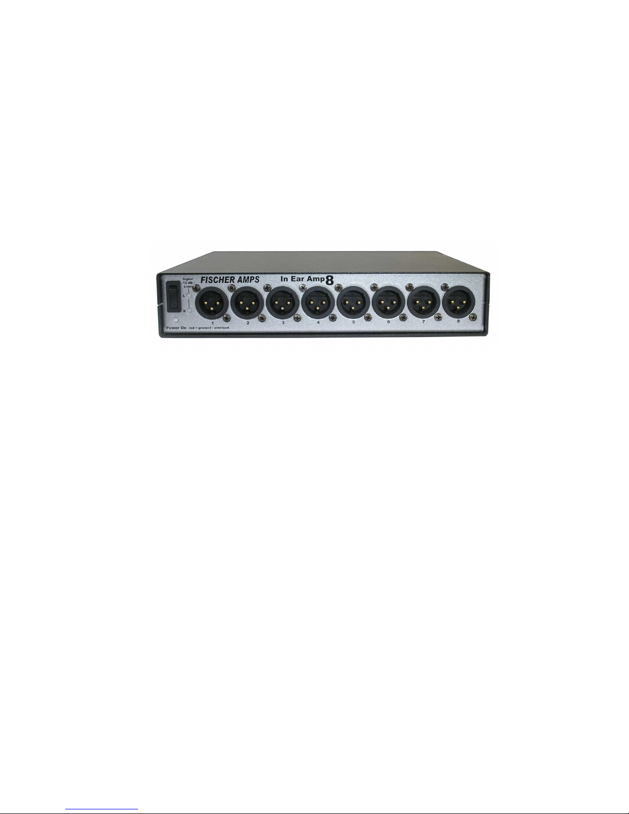
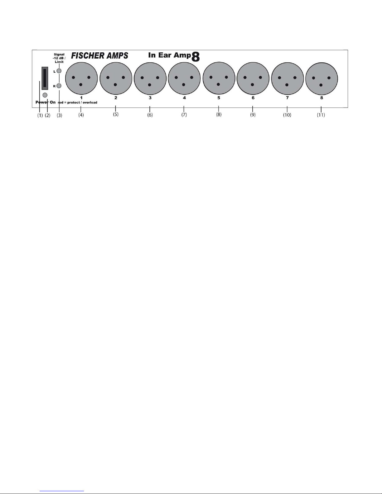
Actuators and Connections Front Side
Description of the actuators (front side) :
(1)
On/Off Switch The operating voltage of the Amp is switched off on the mains side.
When switched off, the Amp needs no power from the mains.
(2)
Control-LED After switching on the Amp, the LED below the off/off power switch
illuminates red for approx. 3 seconds and then changes to green. IN
case of a defect inside the Amp or in case of overload, the internal relay
cuts off the headphone output from the electronics and the LED
illuminates red. If the LED does not change to green after switching on
the Amp, there is an overload or the Amp is defective.
(3)
LED level indicator Indicates the internal working level with two duo-LEDs (one each for left
and right). Green indicates an input level of -15dB to +2dB, the red LED
is illuminated when the level is +2.5dB or higher. Adjust the signal
source (mixing console) so that there is a level of approx. 0dB at the
output. With signal peaks, the red LEDs should flare up slightly. This
guarantees a correct operating level of the limiter for instance with
sudden level changes.
(4-11)
Earphones Outputs Eight 3-pole, XLR male headphone/earphone jacks to connect a 3-pole
standard microphone line in combination with the Fischer Amps Mini
Body Pack XLR. With standard microphone cables, up to eight
musicians can be supplied with the stereo signal of the In Ear Amp 8.
The headphone signal can also be transmitted by a multicore or sub-
multicore without needing an adaptor. The eight outputs are connected
internally to a powerful headphone amplifier and all have the same
output level. The artists can adjust their individual volume at the passive
volume control of the Mini Body Pack. Position “Low” of the output level
switch at the rear side of the unit allows headphone impedances from
12 to 40 ohms per output. Position “High” of the output level switch
allows headphone impedances > 40 ohms. The XLR output connectors
have following assignment: Pin 1 = Ground, Pin 2 = signal left, Pin 3 =
signal right.

3
Actuators and Connections Back Side
(1 / 2)
Combined XLR-
Jack Connections
Channel 1 (left), Channel 2 (right)
Connections of the input signal fromthe mixing console or other audio
sources. Assignment of the combined XLR connection:
XLR Stereo jack ¼“
Pin 1 = Ground Sleeve
Pin 2 = Signal + Tip
Pin 3 = Signal – Ring
With asymetric wiring with XLR cables, PIN 3 should be assigned to
ground (bridge in connection plug). Nominal input level 0dBu, adjustable
at front side from –10 dB to +12 dB, input impedance 10kOhm.
(3 / 4)
Link Outputs
Channel 1 and 2 XLR outputs to loop input signals to more Amps.
Pin assignment: Pin 1 = Ground, Pin 2 = Signal (+), Pin 3 = Signal (-)
Please note: With asymmetric connection of inputs 1 and 2, the signal
at the Link Out connectors is unbalanced as well and will not be
balanced internally.
(5)
Line-Output to Shaker Amp When the switch is pressed, the signal at the Shaker Amp Line Out
passes a low pass with a cutoff frequency of 80 Hz / 24 dB-oktave. This
feature is very helpful when using a standard PA amplifier without
integrated frequency crossover for the shaker. The cutoff frequency of
80 Hz corresponds to the optimum working level of the bass shakers.
When the switch is not pressed, the signal is output full range. This is
also the correct switch position when operating the Fischer Amps
Shaker Amp or the ButtKicker Amplifier BKA 1000-4 in combination with
the Fischer Amps In Ear Amp 2, as these units have an integrated,
controllable low pass.
(6)
Ground Lift Button Separates the audio ground from the system and cabinet ground. When
there is a ground loop when connecting various appliances, pressing the
Ground Lift Button can solve the problem. (The cabinet of the In Ear
Amp 8 is still connected with the protective ground of the power supply).

4
(7)
Input Voltage Select
115V /230V Switch to adjust the appliance to the country’s supply voltage 230V AC
or 115V AC. Before switchover, always switch off the appliance and
disconnect the mains cable from the operating voltage. Doing so
prevents overload of the internal PSU. It is not necessary to replace a
fuse in the appliance for adjusting the operating current.
(8)
Power In Jack 3-pole Euro mains socket to connect the provided 3-pole Euro power
cable. To supply the appliance with voltage, connect it to a grounded
power outlet. The metal casing of the appliance is permanently
connected to the internal ground wire. The self-resetting fuses are all
inside the appliance and do not have to be replaced in case of fault, but
reset after trouble-shooting. If the power cable is damaged, replace it by
a new, reliable cable immediately.

5
Specifications
Dimensions: L x W x H: 220 x 190 x 43 mm
Weight: 2.4 kg
Operating Voltage: 115V AC or 230V AC 50/60 Hz, switchable
Power Consumption: 18 W max.
Mains Connection: Euro power connector, 3-pole
Frequency Response: 20 Hz to 50 kHz +/- 1 dB
Power Headphone Amp
(low Level) max. 190 mW, minimum impedance 8 ohms
max. 1.2 V RMS, 0.0026% THD at 1 kHz
Power Headphone Amp
(high Level) max. 400 mW, minimum impedance 40 ohms
max. 4 V RMS, 0.0025% THD at 1 kHz
Limiter in Headphone Amp: yes (cannot be disabled, internal level +4 dB)
Input Connectors: 2 x combined XLR/jack, balanced, 0 dB input level
1 x Stereo Aux-Input jack, unbalanced at front side, -10dB
Outputs: 2 x XLR Link out, 1 x Line Out Shaker-Amp, jack
Headphone Outputs:
1 x XLR male for Guitar In Ear Cable
1 x stereo jack with adaptor 1/8”
WARRANTY:
The manufacturer grants a warranty of 24 months from the date of purchase by the original owner for defects in
materials or workmanship. When the appliance has been subject to misuse or has been altered, the warranty
expires. When returning the defective unit, enclose the receipt, pack the unit to avoid transit damage, and
return the unit carriage prepaid. The manufacturer does not accept carriage forward consignments.
Disposal of Old Electrical & Electronic Equipment
(Applicable in the European Union and other European countries with
separate collection systems)
This symbol on the product or on its packaging indicates that this product
shall not be treated as household waste. Instead it shall be handed over to
the applicable collection point for the recycling of electrical and electronic
equipment. By ensuring this product is disposed of correctly, you will help
prevent potential negative consequences for the environment and human
health, which could otherwise be caused by inappropriate waste handling
of this product.
The recycling of materials will help to conserve natural resources. For more
detailed information about recycling of this product, please contact your
local city office, your household waste disposal service or the shop where
you purchased the product.
FISCHER AMPS
HANS-ULRICH-BREYMANN-STR. 3, D–74706 OSTERBURKEN
TEL: +49 (0) 62 91-648 79 0, FAX: 648 79 19
E-MAIL:
, Internet:
www.fischer-amps.de

6
Assembly Instructions 9.5-inch Units FISCHER AMPS
Dear FISCHER AMPS User:
Our 9.5-inch (half rackspace) units can be used as desktop units, or can be integrated into 19“ racks, either
individually or combined with other 9.5-inch Fischer Amps units.
For assembly, you just need a Phillips screwdriver size 1.
Parts supplied with a 9.5-inch unit (see picture)
Assembly of the brackets when using the single unit in a 19“ rack:
side view side view supplied accessories
Assembly of two Fischer Amps 9.5-inch Units into one 19” 1U:
bottom view
Connection of two units with
connecting plate by means of
8 pcs. M3 x 5 countersunk screws Assembled rackmount unit 1U (with two 9.5” units)
FISCHER AMPS
Hans-Ulrich-Breymann-Str.3, D-74706 OSTERBURKEN, FON +49 (0) 62 91 – 648 79 - 0, FAX 648 79 - 39
E-MAIL: info@fischer-amps.de, Internet: www.fischer-amps.de

7
Notes:
FISCHER AMPS
Hans-Ulrich-Breymann-Str. 3, D-74706 Osterburken / Germany
Phone +49 (0)6291–648 79-0, Fax 648 79-19
E-MAIL:
, Internet:
www.fischer-amps.de
Table of contents
Other Fischer Amps Amplifier manuals


Popular Amplifier manuals by other brands


Bogen
Bogen NYQUIST NQ-GA20P2 Installation and use

Classe Audio
Classe Audio CA-201 Service manual

Crystal Vision
Crystal Vision AADA-VF user manual

FAME
FAME GX60R owner's manual

Lindsay Broadband
Lindsay Broadband LHA 1.2 GHz DOCSIS 3.1 Series instruction manual

Soundstream
Soundstream L1.600D Owner's manual & installation guide


