manuals.online logo
Brands
  1. Home
  2. •
  3. Brands
  4. •
  5. PROception
  6. •
  7. Amplifier
  8. •
  9. PROception proTLA41 User manual

PROception proTLA41 User manual

Page 1Page 8
PD2011-9045-01
Performance data given are typical unless otherwise stated. Proception Limited reserves the right to change
product designs and specifications without prior notice.
2-Year Guarantee
This guarantee covers failure of your PROception product resulting fro anufacturing defect
within a period of 2 years fro the date of supply to the end-user.
This guarantee does not cover da age to the product caused by abuse, ta pering, defective
installation or natural causes such as lightning discharge. Repair or atte pted repair, other than
by the anufacturer, will render this guarantee void.
This guarantee does not affect a consu ers statutory rights.
Proception Limited,
177-187 Rutland Road
SHEFFIELD
S3 9PT
United Kingdom
eb: http://www.proception.co.uk/
e-mail: [email protected]
proTLA41
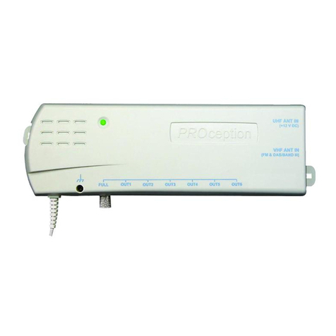
MATV Headend Launch Amplifier
PROception
INSTALLATION INSTRUCTIONS
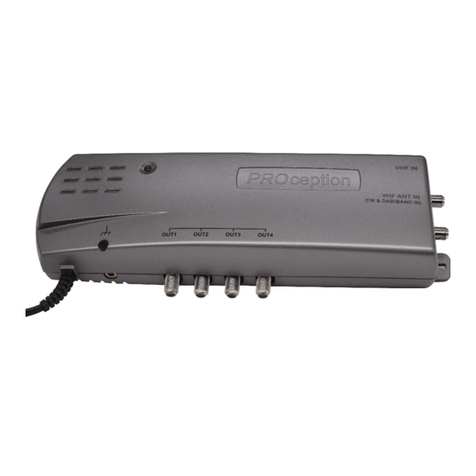
The proTLA41 is a single-output multi-band MATV headend launch amplifier,
suitable for small-to-medium size systems of up to around 1 outlets. The
amplifiers advanced design and push-pull output stage ensure good
intermodulation performance, combined with low power consumption for cool
and economical running.
Three separate antenna inputs are provided for Band II (FM radio), Band III (DAB
or TV) and UHF TV. Each input is well-filtered prior to amplification, giving good
immunity to out-of-band interference from any nearby base stations or similar
transmitters. The gain from the UHF antenna input features a fixed upward
equalisation slope of around 4dB to offset the inevitable increasing cable loss in
the passive distribution network toward the higher frequency end of the band.
Line-power at 5V DC is available at the UHF antenna input for a PROception
proMHD11L or proMHD11M preamplifier which may be required if the off-air
UHF signals are low, or the antenna downlead is long.
A fourth input  AUX UHF  is provided to allow connection of locally-generated
signals such as CCTV. This auxiliary input has lower gain than the main UHF input
to minimise noise degradation of the antenna signals. Each of the four inputs has
its own gain control, allowing simple optimisation of the outgoing signal levels.
The amplifier is intended to be used with a passive distribution network using
splitter and tap-off units from the PROception proSPL and proTAP ranges. It is also
suitable for use in conjunction with the passive terrestrial type of satellite
multiswitch in integrated reception systems (IRS) provided that the gain and output
capability are compatible with the requirements of the particular multiswitch(es)
used. An accurate directionally-coupled monitor point is provided, allowing simple
and precise set-up of the outgoing signal levels  a feature probably unique in an
amplifier of this class.
Application guidance
Passive network design
The amplifier is suitable for feeding passive networks with attenuation of up to
about 32dB at VHF, rising to around 4 dB at the top of the UHF band. The
accompanying application example diagram (Fig.1) shows the star-wired approach
where all the taps are located near to the amplifier, with direct drop cables to
each outlet. With the tap values shown the drop cable length can be up to around
55m of 1  size benchmarked cable. The Fig.1 system is easily scaled for a
smaller number of outlets by omitting some of the tap banks and changing the
initial proTAP812 to a 4- or 6-way splitter to minimise the overall attenuation.
Page 7Page 2
Safety Instructions
OVERHEATING
This amplifier is intended for use in moderate limates only. It should not be used in tropi al
regions. The re ommended ventilation learan es and other pre autions given in the relevant
se tion of this instru tion leaflet should be observed to prevent overheating. No unit should be
fixed where it is likely to be ome smothered by soft furnishing fabri s su h as urtains, or by
thermal insulation material in a roof spa e or building void. Mains powered equipment should
not be left resting on a arpet.
WATER AND FIRE RISKS
The applian e is not waterproof. It is intended for indoor use only and must not be fixed where
it ould be exposed to dripping or splashing water. Obje ts ontaining liquids should not be
pla ed on or near the applian e. To prevent risk of fire, no obje t with a naked flame should be
pla ed on or near the applian e, or its asso iated wiring.
MAINS PLUG AND DISCONNECTION FROM THE SUPPLY
The applian e is supplied with a standard fused plug fitted. If this is unsuitable, refer to the
instru tions below. If you need to hange the fuse in the fitted plug, a 3 Amp fuse to BS 1362
arrying the ASTA or BSI approval mark must be used. Always repla e the plasti fuse arrier
when renewing the fuse. The plug (or other means of dis onne tion from the supply, if used)
should remain readily a essible for operation when ne essary. The LED power indi ator on
this equipment should not be regarded as providing reliable indi ation of supply dis onne tion.
CHANGING THE PLUG
If the fitted mains plug is not suitable for the so ket-outlets in use, it should be ut off and a
new plug fitted.
Wiring the new plug: Instru tions supplied with the new plug should be followed. The brown
wire must be onne ted to the live (L) terminal of the plug and the blue wire to the neutral (N)
terminal. Neither wire should be onne ted to the earth (E) terminal of a 3-pin plug (the
applian e does not require an earth onne tion). Ensure that the ord grip in the plug is orre tly
used and lamps the sheath of the ord firmly.
Fuse Rating: If the new plug is a fused type, the fuse fitted should be rated at not more than
3 Amp.
Caution: The old plug should be destroyed immediately sin e it would be dangerous if plugged
into a live so ket.
G%28 7
352
FHSWLRQ
SUR7$3 
:$<7$3G%
 0+]
,1
7$3 7$ 3 7$3 7$ 3
7$3 7$ 3 7$3 7$ 3
352
FHSWLRQ
SUR7$3 
:$<7$3G%
 0+]
,1
7$3 7$ 3 7$ 3 7$3
7$3 7$ 3 7$ 3 7$3
G%28 7
352
FHSWLRQ
SUR7$3 
:$<7$3G%
 0+]
,1
7$3 7$ 3 7$3 7$ 3
7$3 7$ 3 7$3 7$ 3
$8;8+)
,1 )0$17
,1
'$%
%$1',,,,1
8+)$17
,19
8+) $8; %$1',,, )0
021,725
G% 287
Fig. 1  Application example: 128 point star-wired system using a cluster of
seventeen 8-way taps.
TV
MOD
DAB FM
proTAP812 proTAP817 proTAP814
7 further banks of 2x8 way taps
75 Ω
termination
drop cables
(see text)
Page 6 Page 3
Technical data
reifilpmAhcnuaLdnedaeHVTAM14ALTorp
sdnab&tupnITNAIIdnaBTNAIIIdnaBTNAFH FHXA
1
egnarycneuqerflangiSzHM801..5.78zHM032..471zHM268..074zHM268..074
)gnittes.xata(niaGBd23Bd5.23Bd93-53Bd03
cits
iretcarahcnoitasilauqeniaGtalFtalFepolsBd4.xorppAtalF
ssentalfniaG £Bd1 £Bd1 £Bd5.1
2
£Bd5.1
-diotevitaler(noitcejerretliftupnI
)sniagdnab
Bd42> 86<f zHM
Bd04> 441>f zHM
Bd52> 051<f zHM
Bd52> f>562 zH
M
Bd03> 004<f zHM
Bd7> f>629 zHM
Bd91> 003<f zHM
epytlortnocniaGdne-tnorFdne-tnorFegatsretnIdne-tnorF
reifilpaerpFH
UrofrewopeniL.xaA52taV5
3

sretemarapnommoC
)stupnilla(egnarlortnocniaG)Bd02.pyt(Bd61>
erugifesioN )FHUXUAtpecxesdnab&stupnilla(.py
tBd7
)VTeugolanahtiw(ytilibapactuptuO )levelrewoltaBAD&MF,TTDsulp(slennahcVTeugolana5rofVµBd011
)VTlatig
id-lla(ytilibapactuptuO )levelrewoltaBAD&MFsulp(sexuTTD7ro6rofVµBd401
tnioprotinoM Bd02>ssolnrutertuptu
ohtiwepytlanoitcerid,Bd1±03noitaunettA
tneeriuqerrewopsniaMW5.6.xorppatazH05V032)AV8(
epytrotcennoclangi
S)42-96106CEI(F
egnarerutarepetgnitarepOC°04+..01-
ecnailpocsdradnatS dedivorplaniretgnidnob;6002:2-3
8005NESB:CME;2002:56006NESB:ytefaS
Notes
1. This input is intended for connection of locally generated signals such as CCTV.
2. The UHF ANT input has a fixed up ard gain slope of approx. 4dB. Gain flatness figure allo s for corresponding
do n ard cable slope.
3. Recommended preamplifiers: PROception types proMHD11L & proMHD11M. Not suitable for po ering 12V
preamplifiers.
UHF preamplifier power
A PROception masthead preamplifier can be used if necessary to obtain sufficient
TV signal level at the main UHF input. The headend amplifier will automatically
power a proMH 11L (9dB gain) or proMH 11M (16dB gain) preamplifier. The
line-power will automatically shut down if no preamplifier is used and the antenna
presents a C short circuit.
Any attenuator connected to the UHF antenna input should be of the C-blocked
type (e.g. PROception type proATT20V). In special cases where the input line power
is not required it can be completely disabled by means of an internal jumper link.
Please contact Proception technical support for details of how to use this facility.
Using the auxiliary UHF input
This input is provided to allow simple connection of local TV sources such as a
security CCTV camera (via a suitable modulator). It is not recommended to use
this input for additional off-air sources unless separate input filtering is provided.
The launch level of any auxiliary analogue TV channels on the system should be
kept to the minimum necessary to obtain adequately noise-free pictures. Local
modulator channel(s) must of course be carefully chosen, avoiding N±1 and N±5
relationships with the main off-air channels.
The gain via this input is adequate for use with modulators having an output level
around 75dBµV  e.g. the PROception proMO 1. Any external gain added ahead
of the AUX UHF input must be kept to an absolute minimum, otherwise the C/N
ratio of the main off-air UHF signals will be degraded.
Page 4 Page 5
Cables and signal connections
To preserve RF screening integrity the signal connections to the unit should be
made using good quality coaxial cable and connectors. This is particularly important
with digital terrestrial TV (DTT to minimise the ingress of impulsive electrical
interference from electrical appliances. The use of CAI benchmarked cable is
strongly recommended.All signal connections are made with Type-F connectors.
The use of good quality crimp or compression connectors, used in accordance
with the manufacturers instructions will give the best results. The importance of
achieving sound braid connections cannot be over-stressed. Completed connections
should always be tightened with a spanner  leaving them finger-tight can
sometimes lead to poor connections and attenuation of the signal.
Unused inputs
If either of the VHF inputs and/or the AUX UHF input are not to be used the
corresponding gain controls should be turned to minimum. Provided that this is
observed there is no need to fit terminating resistors.
Mains supply connection and safety notes
The amplifier is supplied with a fitted mains plug and may be plugged directly into
a 13A (BS1363 socket outlet. If socket outlets of a different type are in use,
please refer to the safety instructions on page 7. Alternatively the plug may be cut
off and the amplifier wired into a readily accessible fused connection unit, fitted
with an approved 3 A fuse to BS1362. This method of connection is recommended
for permanent distribution system applications, since it reduces the risk of tampering
and accidental disconnection. If the amplifier is not connected to the mains using
the fused plug supplied, or a fused connection unit, it must be protected by means
of a fuse or MCB at the final distribution board of rating not exceeding 6A.
A readily accessible isolating switch should be provided to allow the unit to be
disconnected from the supply.
Any new fixed wiring installed to supply power to this amplifier should comply
with BS7671 (IEE wiring regulations and, where relevant, Part P of the UK building
regulations. The amplifier is of Class 2 construction and does not require a protective
earth connection. This does not obviate the need to provide a circuit protective
(earth conductor in the supply wiring, as required by BS7671.
System equipotential bonding
All signal distribution systems should comply with the safety requirements of
BSEN60728-11. This effectively requires earthed equipotential bonding of every
system. For further guidance see the CAI code of practice COP03.
The amplifier is provided with a bonding terminal. A bonding conductor of 4mm²
should be provided, connected to the main earth terminal of the electrical
installation which supplies the unit. Bonding may be effected using PROception
proBAR5 or proBAR8 equipotential bonding bars, allowing the amplifier to be
removed for maintenance without disturbing the bonding of the signal cables.
Notes
1. This table is given for general guidance only and assumes a passive distribution network with a nominal loss
between the amplifier output and each system outlet of around 30dB in Band rising to 40dB in BandV
(UHF Group C/D). Different levels may need to be specified if the characteristics of the passive network differ
widely from this. UK transmission parameters are assumed and care should be taken when using the amplifier in
territories with differing transmission standards.
2. Acceptable levels at system outlets are in accordance with the recommendations of DTG R-Book 5.
3. Before DSO the system should be set-up on the analogue TV channels. The pre-DSO digital levels shown assume
that the digital muxes are received at -14dB relative to analogue. n some cases the digital levels will be lower
and care should be taken to ensure that they are within the acceptable range at all system outlets.
4. The post-DSO levels shown are based on a figure of -7dB relative to the former analogue signals. This applies
to the public service (PSB) muxes from most main transmitter sites, so little or no adjustment should be necessary
at DSO in many cases. Where adjustment is needed, or when setting up a new system after DSO, be sure to use
the highest level multiplexes for setting-up. At many sites the commercial (COM) muxes will be around 3dB
lower than the PSB muxes.
5. f a single local analogue TV channel is present on an otherwise all-digital system after DSO (via the AUX UHF
input) it is recommended to set its launch level to be about the same the PSB digital muxes.
dnabdnaepytlangiS
1
tupnielbatpeccA
egnarlevel
dednemmoceR
slevelhcnual
tasleveL
tnioprotinom
steltuometsystasleveL
egnarelbatpe
ccAlanimoN
2
oidarFHV
MFIIdnaBVµBd87..85VµBd09 Vµd06 VµBd06VµBd47..45
BADIIIdnaBVµBd17..15VµBd38 Vµd35 VµBd05VµBd07..03
OSDer
ofebVTFHU
3
ApuorGVTeugoanAVµBd19..17VµBd601 Vµd67 VµBd07VµBd08..06
BpuorGVTeugoanAVµBd19..17VµBd801 Vµd87 VµBd07VµBd0
8..06
D/CpuorGVTeugoanAVµBd19..17VµBd011 Vµd08 VµBd07VµBd08..06
ApuorGVTatigiDVµBd77..75VµBd29 Vµd26 VµBd6
5VµBd56..54
BpuorGVTatigiDVµBd77..75VµBd49 Vµd46 VµBd65VµBd56..54
D/CpuorGVTatigiDVµBd77..75VµBd69 Vµd66 Vµ
Bd65VµBd56..54
OSDretfaVTFHU
5,4
ApuorGVTatigiDVµBd48..46VµBd99 Vµd96 VµBd36VµBd57..54
BpuorGVTatigiDVµBd48..46VµBd101 Vµd17 VµBd36VµBd57..
54
D/CpuorGVTatigiDVµBd48..46VµBd301 Vµd37 VµBd36VµBd57..54
Installation notes
Location and fixing
Choose a suitable central location to fix the amplifier. The location must be dry
and not subject to prolonged ambient temperature conditions of less than -10°C
of more than + 40°C. Fix the amplifier to a sound vertical surface such as a wall
or equipment mounting board. Ventilation gaps of at least 50mm should be left
around the front and sides of the unit. More clearance will be required above and
below the unit to allow access for the signal cables.
When installing the unit in a roof space or similar building void ensure that
it will not come into contact with thermal insulation material
Signal levels
To achieve good performance it is essential that that every system is set-up by a
competent person using an accurate signal level meter or spectrum analyser
connected to the amplifiers monitor point. The following table gives general
guidance: it shows recommended launch levels and the corresponding input,
monitor point and system outlet levels for a typical system, both before and after
the UK digital switch-over (DSO . See the table footnotes for more detail.

Other PROception Amplifier manuals

PROception proAMP11 User manual

PROception

PROception proAMP11 User manual

PROception proAMP108U User manual

PROception

PROception proAMP108U User manual

PROception PROAMP310X User manual

PROception

PROception PROAMP310X User manual

PROception PROAMP11 User manual

PROception

PROception PROAMP11 User manual

PROception proMHD14R Operation and maintenance manual

PROception

PROception proMHD14R Operation and maintenance manual

PROception PROAMP24 User manual

PROception

PROception PROAMP24 User manual

PROception proAMP310X User manual

PROception

PROception proAMP310X User manual

PROception proAMP11 User manual

PROception

PROception proAMP11 User manual

PROception proAMP24 User manual

PROception

PROception proAMP24 User manual

PROception proUSM Series User manual

PROception

PROception proUSM Series User manual

PROception proAMP24 Mk 3 User manual

PROception

PROception proAMP24 Mk 3 User manual

Popular Amplifier manuals by other brands

DENT Instruments RoCoil TCA-5 Operator's guide

DENT Instruments

DENT Instruments RoCoil TCA-5 Operator's guide

Anthem MCA 50 Specifications

Anthem

Anthem MCA 50 Specifications

Milestone pro MP-A250B user manual

Milestone pro

Milestone pro MP-A250B user manual

Audio Note Conquest Silver user manual

Audio Note

Audio Note Conquest Silver user manual

Omnitronic PAM-150 user manual

Omnitronic

Omnitronic PAM-150 user manual

Denon Professional DN-333XAB user guide

Denon Professional

Denon Professional DN-333XAB user guide

Vitus Audio SIA-025 owner's manual

Vitus Audio

Vitus Audio SIA-025 owner's manual

Sansui AU-5900 Service manual

Sansui

Sansui AU-5900 Service manual

Fairchild 610 instruction manual

Fairchild

Fairchild 610 instruction manual

Spotwave SpotCell 2500Xe user manual

Spotwave

Spotwave SpotCell 2500Xe user manual

Onkyo TX-860 instruction manual

Onkyo

Onkyo TX-860 instruction manual

icon Audio PS1 Series instructions

icon Audio

icon Audio PS1 Series instructions

Philips BGY1916 datasheet

Philips

Philips BGY1916 datasheet

QSC CM16a Hardware manual

QSC

QSC CM16a Hardware manual

Musical Fidelity V-LPSII instructions

Musical Fidelity

Musical Fidelity V-LPSII instructions

Arcam AVR850 Handbook

Arcam

Arcam AVR850 Handbook

Optimus AM-120Z Installation & operating instructions

Optimus

Optimus AM-120Z Installation & operating instructions

Sony TA-VE700 operating instructions

Sony

Sony TA-VE700 operating instructions

manuals.online logo
manuals.online logoBrands
  • About & Mission
  • Contact us
  • Privacy Policy
  • Terms and Conditions

Copyright 2025 Manuals.Online. All Rights Reserved.