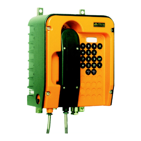
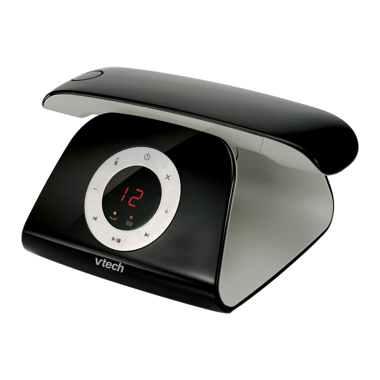
FITRE TLP97 User manual

Portable LB amplified
weatherproof telephone
TLP97
(7147102)
USER MANUAL

The model TLP97 is a durable industrial handphone for 2-way, simultaneous communication.
Utilizing piezo-electric element for voice transmission, it withstands high temperatures and high humidity.
Drip-proof construction. Recommended to be used under severe environments including the tropics,
tunnel, ship, forestry, factory, construction site, etc.
Precautions: Handle the unit with due care not to give excessive shock or heat. Do not immerse the unit in
water. Store the unit under normal temperature and humidity.
1. CONSTRUCTION
The handphone unit contains call signal generator, voice sending amplifier, and two "AA" batteries. On the
operation panel side are Call button (grey) and Talk button (black). No external power source is necessary
for communication.
External view
Sectional view
Name of Each Part
(1) Handset body
(2) Handset cover
(3) Mouthpiece
(4) Earpiece
(5) Cover packing
(6) Transmitter capsule (CE-2)
(7) Receiver capsule (CE-2)
(8) Printed circuit board
(9) Talk button switch
(10) Talk push button
(11) Rubber cap (grey/black)
(12) Call button switch
(13) Call push button
(14) Chassis case
(15) Gland
(16) Gland packing
(17) Cover fixing screw
(18) Capsule packing
(19) Coiled cable
(20) Line connector
(21) Operation panel
(22) Batteries: "AA" x 2

II. INSTALIATION
•Simply connect the line connectors of two TLP97's with 2-conductor cable having core diameter of
approx 0.75mm or larger. Disregard polarity in wiring. Make connection of the cables by stripping the
insulation, and winding a plastic tape on the connected part. The accessory heat-shrink tubes may be
used to cover the spliced wires, by heating it with a heat-air blow, etc.
•More than 2 units of TLP97 can be hooked up on the communication line. The headset type phone
F/AL can also be used in conjunction with TLP97. Note that when the number of phone sets connected
is around 6 or more, the signaling sound may get weaker. The self powered separate bell unit RB-1
(option) may be used in such instance. In case of one-to-one connection, cable length up to approx.
3km should allow operation with adequate buzzer/speech sound volume.
III. OPERATION
1. To start communication, press down CALL (grey) button, and calling signal is . transmitted to the other
party (at the same time you hear the buzzer sound from your handset also).
2. The other party, being signaled by the buzzer, responds to the call by also pressing CALL button.
3. Both parties then simultaneously press down TALK (black) button to commence conversation. While
the TALK button is pressed down at both ends, the conversation can be made in a manner just like an
ordinary telephone. Keep the button pressed down with enough strength.
Note: When more than 2 phone units are hooked up on the communication line, unique signaling code,
like pushing the switch two times, three times, etc. at a time, may be used so that the calling
station can be identified by the buzzer signal.
IV. CHANGING BATTERIES
When the battery power gets low, the buzzer sound will get weaker. To replace the batteries, unscrew the
mouth piece (3) and ear piece (4), and take out the transmitter capsule (6) and receiver capsule (7)
together with their connecting wires. Then remove two handset-cover-fixing screws (17) to take off the
cover. Remove chassis case (14) to replace the batteries with new ones, making sure the polarities are
correctly matched. Although the battery life depends on usage, they may last more than 6 months in
typical use.
2-wire Cable (Vinyl insulated)
Strip the insulation and wrap with vinyl tape

V. SPECIFICATIONS
Power supply 3 VDC (2 "AA" batteries)
Power consumption Call, 120mA; Talk, approx. 5mA
I/O impedance 600 ohm
Call signal 1000-1500 Hz
Dimensions See figur
Weight Approx. 750g
Accessories One wire hanger
4 heat-shrink tubes
Options
Bell Unit RB-I -- The RB-1 is a self powered bell unit which generates signaling sound in greater
volume (80dB). Hooked up to the communication line in the same manner as the phone unit, it can be
utilized under severe noise conditions, or when using the phones across a long distance.
Master Switching Unit MP -- Up to 30 units of F/AL or TLP97 can be connected to the master
switching unit, so that communication can be made between the master unit and the slave phones, or
between slave phones, as selected on the master unit. Types MP-5, MP-10, MP-20, MP-30 are
available, each designation indicating the maximum number of phones to be connected.
Connecting Box -- A ruggedly constructed line-connector box which may be used even under
explosive atmospheres. With the use of special connector, TLP97 could be plugged or unplugged
instantly at the connecting box, which may be mounted on a wall, etc. for permanent installation, in a
designated site along the communication line.
Shock-absorbing Hanger -- A sturdy wall-mounting hanger with spring/rubber hook ideal for
installation in vehicles, ships, etc.
VI. SCHEMATIC DlAGRAM
T1 Transformer 2 kohm:1 kohm
T2 Transformer 600 ohm:10 ohm
T3 Transformer 600 ohm:10 ohm
C1 Capacitor 3,3 µF, 50V
C2 Capacitor 3,3 µF, 50V
C3 Capacitor 3,3 µF, 50V
C4 Capacitor 0,02 µF, 50V
R1 Resistor 50 kohm:1/8W
R2 Resistor 3 kohm:1/8W
R3 Resistor 10 kohm:1/8W
R4 Resistor 50 kohm:1/8W
R5 Resistor 10 ohm: 1/8W
R6 Resistor 100 ohm: 1/8W
R7 Resistor Variable 0-500 ohm
Tr1 Transistor 2SC-458
Tr2 Transistor 2SC-458
Tr3 Transistor 2SC-458
TS1 Com.Sw.
TS2 Com.Sw.
BS Signal Sew.
T Transmitter CE-2
R Receiver CE-2
BT Battery “AA” x 2
CC Cord
CO Connector
Wen mounted
on wire hanger
20142 Milano • Italia • via Valsolda, 15
telefono: (+39) 02.8959.01 • telefax: (+39) 02.8959.0400
e-mail: [email protected]
Other FITRE Telephone manuals
