FITRE TAS 2000 RV Instruction Manual

electronics & telecomunications
F I T R E S.p.A.
7132442Q • rel.201602-B
7132445Q • rel.201602-B
Head Office and Production Units:
20142 Milano (Italy) - via Valsolda, 15
phone: (+39) 02.8959.01
fax: (+39) 02.8959.0400
e-mail: [email protected]
Branch Offices in Roma and Venezia
APPARECCHIO TELEFONICO STAGNO
WEATHERPROOF TELEPHONE SET
P/N 7132445 - P/N 7132442
INFORMAZIONE AGLI UTILIZZATORI
INFORMATION FOR USERS
Ai sensi dell’art. 26 del Decreto Legislativo 14 marzo 2014,
n. 14 “Attuazione della Direttiva 2012/19/UE, sui rifiuti di
apparecchiature elettriche ed elettroniche (RAEE)”
Il simbolo del cassonetto barrato riportato sull’apparecchio indica
che il prodotto, alla fine della propria vita utile, deve essere raccolto
separatamente dagli altri rifiuti.
L’utente dovrà, pertanto, conferire l’apparecchio giunto a fine vita
agli idonei centri di raccolta differenziata dei rifiuti elettronici ed
elettrotecnici, oppure riconsegnarlo al rivenditore al momento
dell’acquisto di un nuovo apparecchio di tipo equivalente, in ragione
di uno a uno.
L’adeguata raccolta differenziata per l’avvio successivo
dell’apparecchio dismesso al riciclaggio, al trattamento e allo
smaltimento ambientalmente compatibile, contribuisce ad evitare
possibili effetti negativi sull’ambiente e sulla salute e favorisce il
riciclo dei materiali di cui è composto l’apparecchio.
Lo smaltimento abusivo del prodotto da parte dell’utente comporta
l’applicazione delle sanzioni amministrative di cui al D.Lgs. n.
22/1997 (articolo 50 e seguenti del D.Lgs. n. 22/1997).
In accordance with the European Directive 2012/19/UE
”about "waste of electrical and electronic equipment (WEEE)
The symbol of the crossed-out wheeled bin on the appliance
indicates that the product, at the end of its life, must be collected
separately from the other waste.
Therefore, the user will have to bring the exhausted appliance to the
apposite recycling centers for electronic and electrical waste, or
return it to the dealer when buying a new appliance of equivalent
type, on a one to one.
An appropriate separate conferral of decommissioned equipment
to the subsequent recycling, treatment and environmentally
compatible disposal, contributes to avoiding possible negative
effects on the environment and health and facilitate the recycling of
materials that composed the appliance.
Illegal dumping of the product by the user entails the application of
administrative penalties as per egislativel provisions of the member
Countries.
TCS 2000 RV
TAS 2000 RV
MANUALE DI
INSTALLAZIONE ED USO
INSTALLATION &
USER MANUAL
La sottoscritta con sede in Milano, via Valsolda 15, dichiara sotto la propriaFITRE S.p.A.
responsabilità che i propri prodotti:
Apparecchi Telefonici Stagni - serie TAS 2000 RV e serie TCS 2000 RV
sono conformi ai requisiti essenziali della (Direttiva R&TTE) ed inDirettiva Europea 1999/5/CE
particolare soddisfano i requisiti richiesti dalle seguenti Direttive Europee:
w2004/108/CE (Compatibilità Elettromagnetica)
w2006/95/CE (Sicurezza Elettrica - Bassa Tensione)
in base all’applicazione delle seguenti NormeArmonizzate:
wEN 55022 : 2010 (Compatibilità Elettromagnetica - Emissione)
wEN 55024 : 2010 (Compatibilità Elettromagnetica - Immunità)
wEN 60950-1 : 2006 +A1 : 2010 (Sicurezza Elettrica - Bassa Tensione)
La sottoscritta dichiara inoltre che i prodotti sopra menzionati sono pienamenteFITRE S.p.A.
conformi alla e infine dichiara che iDirettiva Europea 2011/65/CE (RoHS II - Lead Free Directive)
prodotti stessi sono anche conformi al , non contenendo unaRegolamento Europeo REACH
quantità complessivamente superiore allo 0.1% del proprio peso di sostanze ritenute pericolose e
classificate (Substances of Very High Concern).SVHC
In accordo a quanto sopra riportato, i suddetti prodotti vengono contraddistinti dall’apposito marchio
CE.
The undersigned headquartered in Milano (Italy), via Valsolda 15, declares under itsFITRE S.p.A.
own responsibility that its products:
Weatherproof Telephone Sets - TAS 2000 RV series and TCS 2000 RV series
meet the essential requirements of the (R&TTE Directive) byEuropean Directive 1999/5/CE
complying, in details, the features required by the following European Directives:
w2004/108/CE (Electromagnetic Compatibility)
w2006/95/CE (Electrical Safety - Low Voltage)
and according to the below listed applied Harmonized Standards:
wEN 55022 : 2010 (Electromagnetic Compatibility - Emission)
wEN 55024 : 2010 (Electromagnetic Compatibility - Immunity)
wEN 60950-1 : 2006 + A1 : 2010 (Electrical Safety - Low Voltage)
The undersigned also declares that the above mentioned products are plentyFITRE S.p.A.
conforming to the and lastlyEuropean Directive 2011/65/CE (RoHS II - Lead Free Directive)
declares that the same products are also conforming to the , notREACH European Regulation
containing a total quantity greater than 0.1% of its own weight of substances considered dangerous
and classified (Substances of Very High Concern).SVHC
In accordance to above, the mentioned products are countersigned by the mark.CE
Milano, 18 gennaio 2016
ing. Enrico Borroni
Direttore Tecnico - Technical Director
FITRE S.p.A.
DICHIARAZIONE DI CONFORMITÀ CE
CE CONFORMITY DECLARATION
FITRE S.p.A. • Laboratorio R&S - R&D Department
20142 Milano (Italy) • via Valsolda, 15
phone (+39) 02.8959.01 • fax (+39) 02.8959.0400
TAS2000RV p/n 7132445 • TCS2000RV p/n 7132442Manuale di installazione ed uso • Installation & User Manual
CARATTERISTICHE • FEATURES
TAS 2000 RV • TCS 2000 RV
DATI TECNICI • TECHNICAL DATA
VERSIONI • VERSIONS
Grazie all’applicazione delle più recenti
tecnologie e componentistica elettronica, le
serie di telefoni industriali eTAS2000
TCS2000, in esecuzione stagna IP66,
risultano particolarmente indicate per
l’installazione nell’industria pesante e
comunque in tutte quelle situazioni dove le
condizioni ambientali di esercizio sono
molto gravose.
I telefoni stagni serie eTAS2000 TCS2000
sono idonei per il collegamento diretto a
linee urbane o come derivati da PABX con
alimentazione 60V, 48V o 24V.
TAS2000RV è il modello versione BCA, con
tastiera standard e regolazione del volume
in ricezione; è il modello inTCS2000RV
versione BC, senza tastiera, per
collegamento diretto ad un posto operatore,
con regolazione del volume in ricezione.
Suoneria
• frequenza tono di uscita:
600÷850 Hz (± 10 Hz)
• intensità sonora: circa 95 dB/1m
Selezione ad impulsi
• frequenza: 10 Hz
• rapporto impulsi: 1.6:1 o 2:1
Selezione DTMF
conforme alle norme CEI/IEC
Tensione nominale PABX
24 V, 48 V, 60 V
Temperatura di esercizio
da -20 °C a +60 °C
Grado di protezione
IP66
Peso
circa 5,5 kg
Dimensioni custodia
260,0 x 270,0 x 140,0 mm (LxAxP)
Colore custodia
• coperchio: arancio RAL 2000
• base: nero RAL 9017
TAS 2000 RV p/n 7132445
Telefono BCA con tastiera standard
TCS 2000 RV p/n 7132442
Telefono BC senza tastiera
TAS 2000 RV p/n 7132445
ACB phone set with standard keyboard
TCS 2000 RV p/n 7132442
CB phone set without keyboard
Ringer
• output tone frequency:
600÷850 Hz (± 10 Hz)
• sound intensity: approx 95 dB/1m
Pulse dialling
• frequency: 10 Hz
• break/make ratio: 1.6:1 or 2:1
DTMF dialling
conforming with CEI/IEC rules
Nominal PABX voltage
24 V, 48 V, 60 V
Operating temperature
da -20 °C a +60 °C
Protection degree
IP66
Weight
approx. 5,5 kg
Case dimensions
260,0 x 270,0 x 140,0 mm (WxHxD)
Case colour
• top cover: orange RAL 2000
• base: black RAL 9017
Thanks to its advanced electronic
engineering and the application of the latest
technologies, the andTAS2000 TCS2000
series of industrial phones, IP66
weatherproof, are particularly suited for
installation in heavy industry and in any
case in all those situations where ambient
operating condi are harsh.tions very
T and weatherproofhe TAS2000 TCS2000
phones series are suitable for direct
connection to lines orphone to subscriber
lines ( or equivalent)PBX with 60V, 48V or
24V power supply.
TAS2000RV is the version model, withACB
standard key and volumepad listening
adjustment is CB; the versionTCS2000RV
model, without keyboard, for direct
connection to an , withoperator set listening
volume .adjustment
TAS2000RV p/n 7132445 • TCS2000RV p/n 7132442Manuale Installazione ed utilizzo • Installation & User Manual
INSTRUCTIONSISTRUZIONI
TCS 2000 RV
TAS 2000 RV
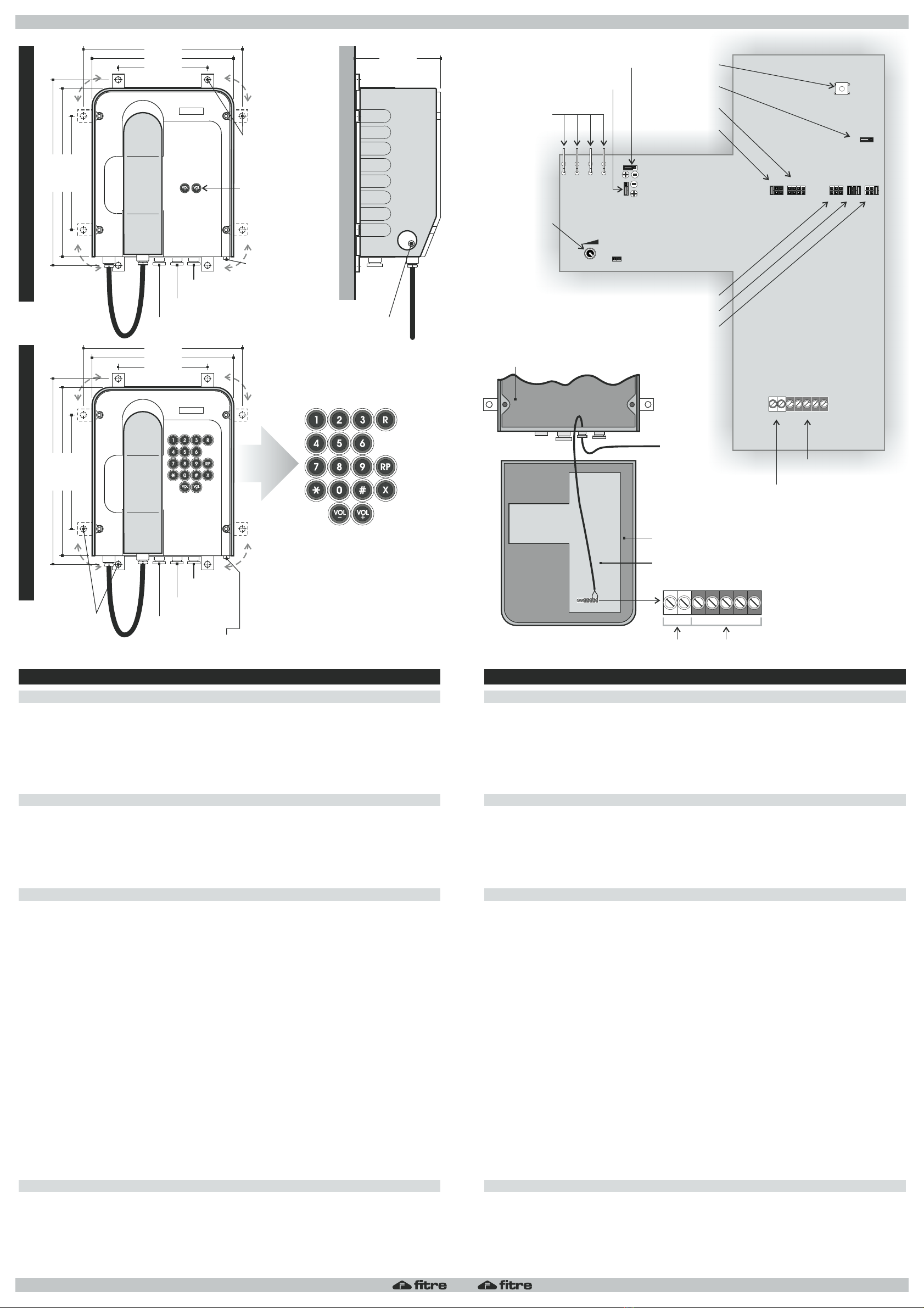
INSTALLATION (picture 1)INSTALLAZIONE (figura 1)
RIPETIZIONE ULTIMO NUMERO SELEZIONATO - solo TAS2000RV (figura 4) LAST NUMBER REDIAL - TAS2000RV only (picture 4)
DESCRIZIONE MORSETTIERE (figura 2) TERMINALS DESCRIPTION (picture 2)
PREDISPOSIZIONI (figura 3) SETUPS (picture 3)
Collegamento alla Linea Telefonica
1. Aprire il coperchio superiore tramite le 4 viti a testa brugola 5 mm frontali
2. Collegare i conduttori del cavo di linea ai morsettiAe B della morsettiera M1 sulla scheda
3. Sganciare il microtelefono
4. Premere il tasto “RESET” sulla scheda
5. Riagganciare il microtelefono
6. Verranno così impostati i corretti volume e tono di suoneria ed il corretto volume del ricevitore
Connection to the Telephone Line
1. frontal 5 mm AOpen the top cover using the 4 llen head screws
2. Connect the line cable toAand B clamps of the M1 terminal on the board
3. Pick up the handset
4. Press the “RESET” key on the board
5. Hang up the handset
6. T and tone of the ringer as well as the right listeninghe correct volume will be set volume
L’ultimo numero selezionato può essere ripetuto premendo il tasto “RP”.
Uno o più numeri iniziali della sequenza possono essere comunque digitati manualmente; la
successiva pressione del tasto “RP” genererà la selezione dei restanti numeri memorizzati.
Ciò è utile per ripetere un numero esterno quando il telefono è collegato ad un PABX,
dovendo selezionare il numero di accesso alla linea urbana ed attendere il tono di urbana.
The last number dial ed can be repeated by pressing the " " .l RP key
One or more initial of the sequence can still be typed manually; thedigits following
depression of the key dialling digits"RP" will generate the of the remaining stored .
This is useful to repeat an external number when the phone is connected to a PABX, having
to dial the access number to the trunk line and wait for the tone.to dialling
Morsettiera M1
A-B poli per collegamento alla Linea Telefonica
T collegamento (eventuale) del conduttore di messa a Terra
S1-S2 collegamento a Suoneria supplementare
Morsettiera M2
A1-A2 contatti per dispositivi ausiliari (equipaggiamento a richiesta)
Terminal M1
A-B poles for telephone line connection
T connection to the (eventual) Earth Loop cable
S1-S2 connection to the auxiliary Ringer
Terminal M2
A1-A2 switches for auxiliary devices (equipped on request)
Impostazione TIPO SELEZIONE - ponticelli J7 (solo TAS2000RV)
33/66 ...............selezione DECADICA - rapporto 33/66 ms (M/B)
40/60 ...............selezione DECADICA - rapporto 40/60 ms (M/B)
MF ...................selezione MULTIFREQUENZA
Impostazione TIPO SELEZIONE OPZIONALE - ponticelli J8 (solo TAS2000RV)
33/66 MF........selezione DECADICA - rapporto 33/66 ms (M/B)Q
la pressione del tasto “ “ sulla tastiera commuta temporaneamente inT
MULTIFREQUENZA, inviando contemporaneamente in linea il codice “ ”T
MF 82/160 .......selezione MULTIFREQUENZA durata 82 ms pausa 160 ms
33/66 20pps.....selezione DECADICA - rapporto 33/66 ms (M/B) 20 pps
40/60 20pps.....selezione DECADICA - rapporto 40/60 ms (M/B) 20 pps
Impostazione TASTO “R” - ponticelli J9/J10 (solo TAS2000RV)
EARTH (J9) .....tasto “R” = TERRA
FLASH (J10)....tasto “R” = FLASH
Impostazione TEMPO DI FLASH - ponticelli J11 (solo TAS2000RV)
100 ..................tempo di FLASH = 100 ms
270 ..................tempo di FLASH = 270 ms
600 ..................tempo di FLASH = 600 ms
Impostazione LINEA URBANA/PABX - ponticelli J6/J12/J13
Linea Urbana...RX (J12) = - TX (J13) = - AGC (J6) = ONRR
PABX ...............RX (J12) = - TX (J13) = - AGC (J6) = OFFSS
Impostazione VOLUME SUONERIA
RING VOL .......potenziometro per regolazione del volume suoneria
DIALLING MODE setting - jumpers J7 (TAS2000RV only)
33/66 ...............PULSE dialling - ratio 33/66 ms (M/B)
40/60 ...............PULSE dialling - ratio 40/60 ms (M/B)
MF ...................DTMF (tone) dialling
OPTIONAL DIALLING MODE setting - jumpers J8 (TAS2000RV only)
33/66 MF........PULSE dialling - ratio 33/66 ms (M/B)Q
la pressing the “ “ key, dialling will temporary change to DTMF mode,T
sending at the same time the “ ” code as first key entry to the lineT
MF 82/160 .......DTMF dialling duration 82 ms pause 160 ms
33/66 20pps.....PULSE dialling - ratio 33/66 ms (M/B) 20 pps
40/60 20pps.....PULSE dialling - ratio 40/60 ms (M/B) 20 pps
“R” KEY setting - jumpers J9/J10 (TAS2000RV only)
EARTH (J9) .....“R” key = HEARTH LOOP signalling
FLASH (J10)....“R” key = FLASH signalling
FLASH TIME setting - jumpers J11 (TAS2000RV only)
100 ..................FLASH time = 100 ms
270 ..................FLASH time = 270 ms
600 ..................FLASH time = 600 ms
C.O. LINE/PABX setting - jumpers J6/J12/J13
C.O. Line .........RX (J12) = - TX (J13) = - AGC (J6) = ONRR
PABX ...............RX (J12) = - TX (J13) = - AGC (J6) = OFFSS
RINGER VOLUME setting
RING VOL .......potentiometer for adjustment of ringer volume
ABTS1
S2
A1A2
Flash/Terra
Rilascio
Rip. Ult. Numero.
Pausa
Regolazione
Volume Ricevitore
Tasti di Selezione
Flash / Earth
Line Reset
Redial
Pause
Receiver
Volume Adjusting
Dial Keys
R
X
RP
VOL- / VOL+
0÷9 / / #Q
S2 S1 T B AA2 A1
RINGER
VOLUME BUZZER OUT
RESET
RIC+
RIC-
MIC-
MIC+
FS1
FS2
FS3
FS4
J6
AGC
OFFON
J9
EARTH
J7
40/60
MF
33/66
J8
33/66 20PPS
40/60 20PPS
MF 82/160
40/60 *MF
FLASH
J10
270
600
100
J11
TX
J13
J12
RX
A2 A1 S2 S1 TBA
M2 M1
M2 M1
260.0 mm
300.0 mm
300.0 mm
260,0 mm
230.0 mm 140.0 mm
270.0 mm
270.0 mm
230,0 mm
145.0 mm
185.0 mm
185.0 mm
145,0 mm
BUSSOLA ROTAZIONE COPERCHIO
TOP COVER ROTATION PIN
MORSETTO DI TERRA
GROUND BOLT
MORSETTO DI TERRA
GROUND BOLT
n. 4 pz./pcs.
STAFFE DI FISSAGGIO
ciascuna con due posizioni
FIXING BRACKETS
with two positions each
n. 4 pz./pcs.
STAFFE DI FISSAGGIO
ognuna con due posizioni
FIXING BRACKETS
with two positions each
REGOLAZIONE
VOLUME RICEVITORE
RECEIVER VOLUME
ADJUSTING
TAPPO M20
M20 PLUG
TAPPO M20
M20 PLUG
MORSETTIERA “M1”
TERMINAL BLOCK “M1”
MORSETTIERA “M2”
TERMINAL BLOCK “M2”
PONTICELLO “J7”
JUMPER “J7”
REGOLAZIONE
VOLUME SUONERIA
RINGER VOLUME
ADJUSTMENT
PONTICELLO/ “J9”JUMPER
PONTICELLO/ “J10”JUMPER
PONTICELLO/ “J11”JUMPER
PONTICELLO “J8”
JUMPER “J8”
PONTICELLO “J6”
JUMPER “J6”
TASTO DI RESET
RESET KEY
PONTICELLO “J13”
JUMPER “J13”
PONTICELLO “J12”
JUMPER “J12”
COLLEGAMENTI
MICROTELEFONO
HANDSET
CONNECTIONS
INTERNO APPARECCHIO (BASE APERTA)
DEVICE INTERIOR (OPEN BASE)
INTERNO APPARECCHIO (COPERCHIO APERTO)
DEVICE INTERIOR (OPEN COVER)
CAVO LINEA TELEFONICA
TELEPHONE LINE CABLE
SCHEDA CIRCUITO STAMPATO INTERNO
INTERNAL PRINTED CIRCUIT BOARD
TAPPO M20
M20 PLUG
TAPPO M20
M20 PLUG
PRESSACAVO M20
M20 CABLE GLAND
PRESSACAVO M20
M20 CABLE GLAND
FIG./PIC. :4
Tastiera del telefono
Telephone Keypad
FIG./PIC. :1
Collegamento alla
Linea Telefonica
Connection to the
Telephone Line
FIG./PIC. :3
Vista Scheda C.S.
(a coperchio aperto)
P.C. Board View
(with cover open)
FIG./PIC. :2
Morsettiere Collegamenti
Connection Terminals
This manual suits for next models
3
Other FITRE Telephone manuals


