flakt woods EQKA User manual
EQKA Cooling unit Contents Page
Safety Directions 2
Technical Data 2
lectric Connections 3
Installation and Commissioning 4
Operation and Care 5
Use 6
Maintenance 7
Troubleshooting 8
Refrigeration Flow Chart 9
Docking 10
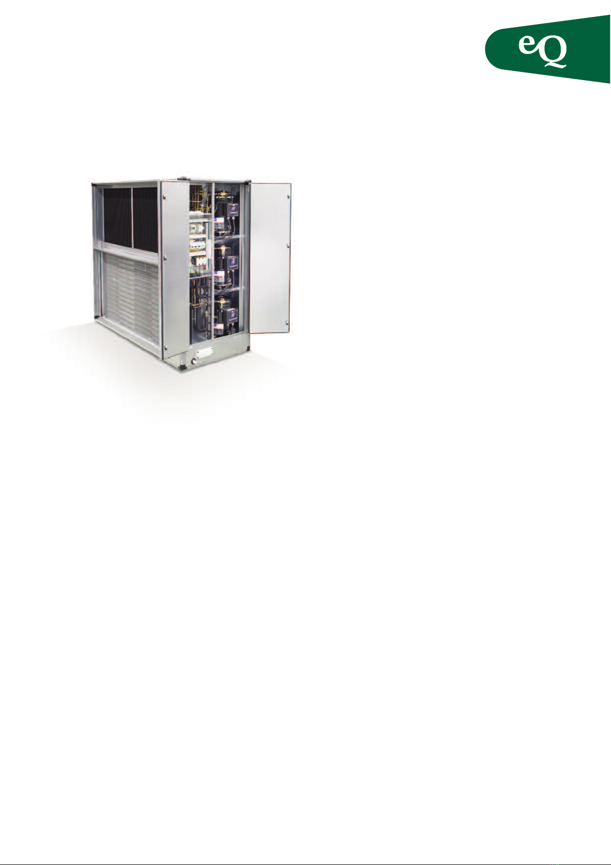
EQKA Cooling unit
Fläkt Woods 8643 B 2012.11 1 We reserve the right to alter specifications
Installation and Maintenance Instructions

Safety Directions Compulsory declaration and recurring
inspection
Declaration of possession of cooling equipment must
be submitted to the local inspection authorities, in
most cases the Public Health and nvironment
Authority in your municipality, if including this
cooling unit the total amount of refrigerant charged in
your operations amounts to more than 10 kg.
Recurring inspection
Recurring inspection, i.e. leakage searching of the refri-
gerant system that must be done at least once annually
by an accredited inspectorate (normally a refrigeration
service company), See under “Maintenance”.
EQKA Cooling unit
Fläkt Woods 8643 B 2012.11 2 We reserve the right to alter specifications
Installation and Maintenance Instructions
Important!
– The unit must NOT be used for pur-
poses other than as a cooling unit.
– The cooling unit’s Operating & Main-
tenance Instructions must be studied
carefully before starting/ operating/
servicing/maintaining/scrapping
the unit.
Keep these instructions in a safe place
for future reference!
– All service and maintenance must be
carried out by a professional!
Service/maintenance of the cooling
system must only be carried out by an
accredited company and qualified
personnel wearing required protective
equipment (gloves and protective eye-
glasses).
– Automatic start! Open and lock the
main switch of the cooling unit before
beginning any work on the unit!
– Do NOT stand on the cooling unit!
– Use only genuine spare parts for
maintenance!
Neglect to comply with any of the
above terms can involve a serious
safety risk and nullify the guarantee/
product liability!
Size Capacity Nom. Cooling Max. Max.
(a) Variant Capacity Current Current Circuit Circuit Circuit Circuit Total
(c) (kW) (A) (A) 1234
008 1 13 9,3 18,5 1,4 2,1 3,5
008 2 15,5 11,2 22 1,6 2,4 4
011 1 15,5 11,2 22 1,6 2,4 4
011 2 24,5 17,3 36,1 2,6 3,9 6,5
018 1 28 20 40,6 3,0 4,5 7,5
018 2 37,5 25,9 50,3 4,0 6,0 10
023 1 44 27,8 58,6 4,8 7,2 12
023 2 56 35,3 71,6 6,0 9,0 15
032 1 58,5 37,3 69,8 6,0 9,0 15
032 2 73,5 49,9 104,8 7,6 11,4 19
041 1 69 49 88 8,0 12,0 20
041 2 98,5 58,8 117,3 8,6 8,6 8,6 26
050 1 98,5 58,8 117,3 8,6 8,6 8,6 26
050 2 125,5 81 10,9 10,9 10,9 33
072 1 125,5 81 10,9 10,9 10,9 33
072 2 151 89,2 10,0 10,0 10,0 10,0 40
The fuse protection should be sized by a qualified electrician.
3 x 400 V
Technical Data - EQKA
3 x 230 V
Fläkt Woods 8643 B 2012.11 3 We reserve the right to alter specifications
Installation and Maintenance Instructions
EQKA Cooling unit
Electric Connections
Check that the cooling unit has been switched off with
the main switch. The electric connections are wired on
the main switch.
The direction of rotation of the compressorsdepends on
the sequence of the phases. The cooling unit must be
wired with the correct phase sequence; otherwise an
alarm will be initiated. The alarm chain of the cooling
unit can also transmit a group alarm signal to an external
monitoring unit. ( Q air handling unit or another unit
across a monitoring unit).
This alarm group can be obtained as potential-free
contacts at pins 57 and 58 on wiring terminals.
To prevent unnecessary stops and alarm from the
cooling unit, it should be interlocked across the extract
air fan, FF.
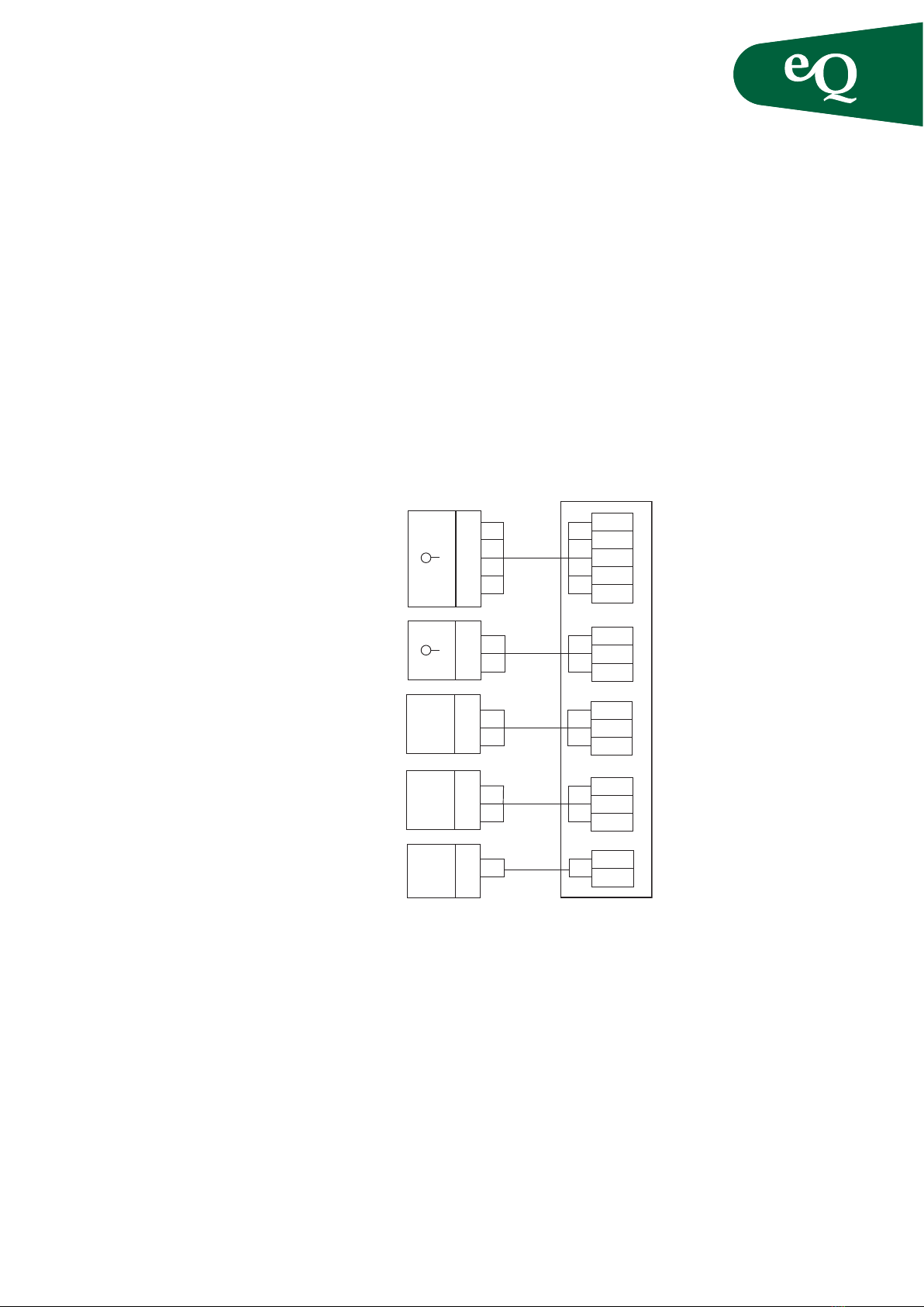
Connect the cooling unit as illustrated in the wiring
diagram below.
Incoming
3x400V supply
To be connected
to main switch in
cooling unit.
L1
L2
L3
N
PE PE
PE
N
QO1.6
QO1.4
QO1.2
Outgoing
group alarm
(closes on an alarm)
58 NO
57 C
2
1
2
PE PE
1
2
3
PE
1
2
3
44
PE
1
PE
54
53
2
1
2
PE PE
1
C
NC
PE
56
55
2
1
2
PE PE
1
C
NO
52
51
2
1
20-10V
1
+
–
Interlock across possible
outdoor thermostat, GT
(otherwise fit with jumper)
Interlock across
extract air fan
0-10V DC control signal
External wiring diagram
Fläkt Woods 8643 B 2012.11 4 We reserve the right to alter specifications
Installation and Maintenance Instructions
EQKA Cooling unit
Installation and Commissioning
Connection of the water-cooled condenser
Cooling units equipped with a KD-W water-cooled
condenser (see unit specification) must be connected to
a mains water supply having a minimum pressure of 0.5
bar and a maximum pressure of 10 bar. Use an appropri-
ate coupling for connecting the mains water supply (see
pipe connection instructions on the cooling unit).
Follow the arrows carefully. If heat is recovered, the
drain water must be connected to an accumulator tank.
Important!
Check list
– Always study the safety directions
on page 2 before beginning all work!
– The air handling unit must not be
commissioned until the installation
had been inspected according to the
check list below!
Before commissioning check the
following:
– Condition on delivery - no transport
damage, installation site, (adequate
lighting, supporting surface etc.)
– No leakage of compressor oil
– Follow-up tightening of the Rotalock
connection
– Phase sequence and retightening of
the power supply connection
– Cooling control signal from the air
handling unit
– Cooling energy recovery not enabled
– Crankcase heater is operating
– Condensate drainage, cooling instal-
lation report submitted
– There are no loss cables
After commissioning check the
following:
– outdoor-/suppllyair temperature
– condensation-/evaporating
– hot gas temperature/
subcooling/overheating
– operating currents
– information to staff-performed.
In a cooling unit with KD-W water-cooled condenser,
the mains water supply must not be shut off.
To start the cooling unit
If the cooling unit is commissioned in cold weather, i.e.
when the temperature is below +15 °C, the compressors
mustbepre-heated:Settheprotectivemotorswitchofthe
compressors to position 0 (Off). Set the main switch insi-
de the cooling unit to position 1 (On) and activate the
control circuit fuse. The crank case heater now heats up
the compressor. If the ambient temperature is below +15
°C, wait for 4-8 hours until the compressor has become
warm, before you start up the compressors.
To set the setpoint for cooling
When cooling is required, the controller in the air
handling unit transmits a control signal (0 – 10V) to the
cooling unit which switches in the capacity steps in
proportion to the signal.
Performance check
The performance of the cooling unit can be tested by
temporarily lowering the cooling setpoint to the point
that the cooling unit starts up.
Inspection
For a description of the control unit, see page 9. The
control function of the air handling unit should include
a minimum temperature sensor in the supply air located
as far as possible from the air handling unit, and a room
or extract air sensor. The cooling unit should be inter-
locked across the extract air fan (and also an outdoor
thermostat). It is important that the compressors stop if
the extract air fan stops. Due to the location of the con-
denser coil, so-called cooling energy recovery cannot be
utilizedatthesametimeasthecoolingunitisinoperation.
High pressure condenser, KD
If condenser heat cannot be emitted into the extract air,
KM1 (“Capac.Control”) will first be automatically swit-
ched off, however if this is insufficient, the high pressure
switch will open and must be manually reset, (see page 9).
Alarm
All the alarms are indicated on the display of the
control unit (see page 10). Potential-free closure is on
the wiring terminal for group alarm transmission, if
required.
Important!
If the unit is installed outdoors, the
heat carrier must contain an appro-
priate mixture of anti-freeze agent to
suit the climate.
Important!
If anti-freeze agent is used, the unit
must have a closed system for the heat
carrier.
Fläkt Woods 8643 B 2012.11 5 We reserve the right to alter specifications
Installation and Maintenance Instructions
Operating and Care
Description
The cooling unit is a part of the air handling unit and
should be installed as a module in the U air handling
unit.
The cooling unit operates independently and has its
own cubicle; however cooling capacity must be swit-
ched in according to signals from the air handling unit.
The cooling unit is designed for cooling the supply air in
the temperature range of between +20 – +32 °C. It is
possible to lower the supply air temperature by 9 – 16 °C
depending on the selected capacity variant, air tempe-
ratures and air volume ratio: supply air/extract air.
Use
An electric equipment cubicle is installed in the service
section of the cooling unit. The cubicle contains mainly
the following items of equipment:
– Main switch
– Control circuit fuse
– Protective motor switch
– Control unit with display
Refrigerant tank
Component description
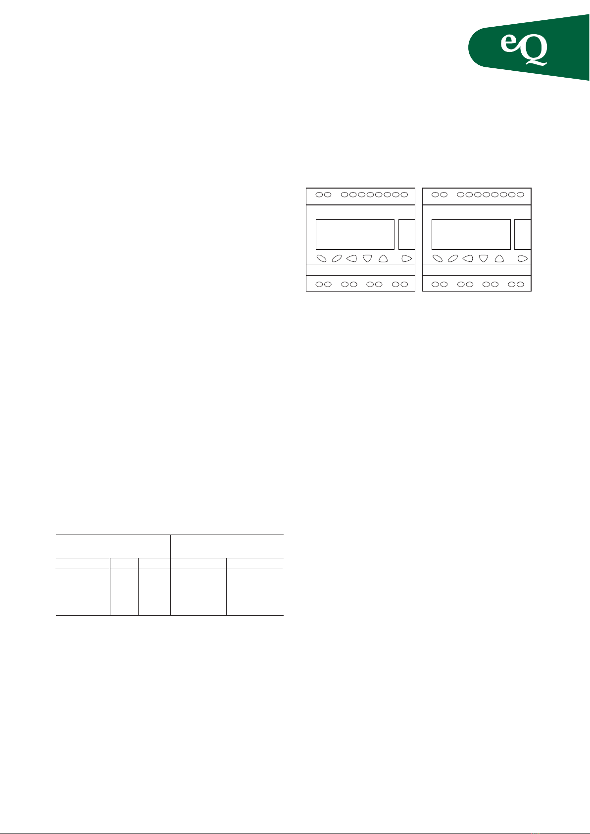
Control unit (RC1)
The control unit is located in the door of the cubicle.
See the description on page 9.
Control circuit fuse
To reset the miniature circuit breaker, pull the black
actuator button upward.
Main switch
Use the main switch for switching the cooling unit
on/off. Always switch off the main switch on the
cooling unit and lock it in position before beginning
work! Certain wiring terminals can be energized despi-
te the fact that the switch is switched off, for example
terminals for group alarm outputs.
EQKA Cooling unit
Warning!
The refrigerant tank is intended for
use as a ”passive” container only, i.e.
it must NOT be connected while the
unit is normally operating. (Applies
to units with refrigerant tank).
Important!
Always study the safety directions on
page 2 before beginning all work!
Warning!
The control circuit fuse does NOT
switch off the voltage to the entire
cooling unit! Always open the main
switch on the cooling unit and lock it
in position!
Fläkt Woods 8643 B 2012.11 6 We reserve the right to alter specifications
Installation and Maintenance Instructions
EQKA Cooling unit
Functions, eneral
The compressor’s capacity is controlled by an external
control signal of 0 – 10V. Its operation is interlocked via
the extract air fan contactor and possibly an outdoor
thermostat as well as via a phase rotation relay.After the
fan starts, the compressors are interlocked for 2 minutes
– delayed start of the compressors (“Startwait 2 min.” is
shown in the display”).
Delayed restart
The compressors cannot start again until after a
300/305/310/315 second idle time (KM1/KM2/KM3/
KM4). During this time “ Startwait 2 min.” flashes in the
display if the relevant compressor needs to be started.
Capacity control (Capac. control)
Compressor 1 has a special high pressure switch for
capacity control.
If the condenser pressure is high, compressor 1 is stopp-
ped and is then allowed to restart after 300 sec.
The text "Capac." alt ”1= capacity control” is shown in
the display while capacity control is in progress.
Compressor protection
ach compressor is protected by a high pressure switch
and motor protection. The compressors are protected
fromincorrectphasesequenceviaaphase-sequencerelay.
The oil heater is switched in while the compressors are
not in operation.
Stepping levels
The various compressor steps are switched in at the
following signal levels:
Cooling unit with hot gas bypass
On a 20% control signal, the ICM2 with hot gas valve
starts in the fully open position. The hot gas valve
closes linearly between 2 and 8 V. The KMI starts at 8 V
and the valve opens 40%.
Between 8 and 10 V the valve closes again.
Stepping levels
Stepping out of each step occurs 20%(2.0V) during
stepping level for 2 or 3 compressors and 10% (1.0v)
During the stepping level for 4 compressors.
roup alarm
For all alarms, the group alarm relay is energized for
possible external alarm indication.
Display texts
Line 1 shows the type of Cooler
Cooler KM1-2, Cooler KM1-2 bin.
Cooler KM1-3, Cooler KM1-4 bin.
Signifies that the steps are switched in binary mode.
Lines 2 and 3
Show the in-service status of compressors 1-4
Start, (flashes in the event of time-delayed start of KM)
Run, (operation of KM)
Capac. or capacity control
AlarmH, or AlarmHigh pres
AlarmL, or AlarmLowpres
AlarmQ, or AlarmQ1/term.
(Q=motor protection and term= thermistor.
Line 2 can also show
* 3-Phase alarm *
Line 3 can also show
* Fan stop *
* Startwait 2 min *
Line 4
Shows input control signal as 0 – 100%:
Signal %058.
PressAto see the compressor running time and possible
control signal to SV1 (valve for hot gas bypass).
Program
The control unit is programmed on delivery and its
settings cannot be changed.
Cooler KM – 4
1= Capac. 3 = Run
2= Start 4 = Alarm H
Signal % 082
A B ESC – + OK
KM1–4 Run time (h)
1= 00242 3= 00154
2= 00228 4 = 00125
Signal SV1 % 098
ABESC– + OK
Compressor 34Compressor 2
1 30 % 20 % 1 30 %
2 60 % 40 % 1 60 %
3 90 % 60 % 1 + 2 90 %
4 80 %
Straight-line stepping
Number of compressors
Binary stepping
Number of compressors

Fläkt Woods 8643 B 2012.11 7 We reserve the right to alter specifications
Installation and Maintenance Instructions
EQKA Cooling unit
Maintenance
Inspection/maintenance
The unit is designed for fully-automatic operation;
however it does require a some regular inspection and
maintenance.
Moreover in accordance with legislation in force,
”Recurring Inspection” must be carried out by an accre-
dited refrigeration service company.
Inspection
To be carried out by the owner/user once a week.
Check (see/listen to) the following:
1. Indicated alarms
2. Abnormal noise/vibrations
3. Leakage of medium (oil, water)
4. Corrosion, wear
5. Suspension, fixation items
6. The interior of the unit, light fittings
Maintenance
To be carried out by a refrigeration service company or
equivalent at least once each year.
Check the following:
1. vaporation/condensation temperature.
2. Hot gas temperature.
3. xpansion valve (overheating of suction gas).
4. Safety equipment (tripping function on the pressure
switches).
5. Cooling capacity
6. Control/feedback control equipment (Performance
check)
7. lectric equipment (retightening of power supply
connections)
8. Cleaning (Coils, drip tray, drainage)
9. Air filter
Recurring checks
Mustonlybecarried out byarefrigerationservicecompany.
Inspect the system at least once every 12 months and main-
tainajournal. Check thefollowingwhereverapplicable:
1. Piping
2. Inspection to detect leakage from the refrigerant
system
3. Check for abnormal vibration
4. Check to detect possible corrosion
5. Whether filling with additional refrigerant is needed
6. Check to detect possible oil leakage
7. Safety equipment
8. Connection joints/Seals
Dismantling
When dismantling (scrapping) this type of unit, the
refrigerant and compressor oil must unconditionally be
collected and contained for destruction/recycling.
Spare parts
Spare parts can be bought via local cooling suppliers.
Contact your local Fläkt Woods office for information
regarding components that need to be replaced.
Important!
Always study the safety directions
on page 2 before beginning work!

Fläkt Woods 8643 B 2012.11 8 We reserve the right to alter specifications
Installation and Maintenance Instructions
EQKA Cooling unit
Troubleshooting
To reset the pressure switch
A pressure switch is mounted on each compressor
To reset the protective motor switch:
The protective motor switches are mounted in the control
equipment cubicle.
Remedial measures
Check that there is voltage on all
phases and that the phase sequ-
ence is correct.
Startthefans ortestbyfitting a jumper
betweenwiringterminals55and 56.
Wait 2 minutes for the dampers to
open before starting the cooling unit.
High pressure switch has tripped.
Reset button is on the pressure
switch. The load is too great or
there is too little air. Check that
filter and coils are not clogged.
Low pressure switch has tripped.
Ingoing air temperature is too low or
there’s a shortage of refrigerant.
Tripped motor protection or ther-
mistor. Press motor protection
button to reset it or let the com-
pressor motor cool off.
Check after resetting the motor
protection that the compressor
operates without abnormal noise.
High pressure switch with automatic
reset has tripped and compressor 1
is switched off for 5 min.
Check that filter and coils are not
clogged.
Check that the control signal is at
least 30% for start of first com-
pressor.
To start all the compressors, the
signal should be at least 90%
Current compressor will start after
a delay of approx. 5 min. Wait!
Current compressor should now
have started. If not, check that
voltage is coming from the com-
pressor contactor. If there is vol-
tage, the compressor is probably
defective.
Display text:
*3-phase alarm *
*fan Stop *
* Start wait 2 min *
’Alarm H’ alt.
’Alarm High pres.’
’Alarm L’ alt.
’Alarm low pres.’
Alarm Q alt.
Alarm Q1 / Term
1= Capac. alt.
1= Capac. Control
Signal % <030
1/2/3/4 = start
1/2/3/4 = run
Ca tion!
Faults should always be cleared without
delay!
All service and maintenance should be
performed by professionals!
Service/maintenance of the cooling sys-
tem must only be performed by accre-
dited company with authorized per-
sonnel wearing protective equipment!
Press here

Fläkt Woods 8643 B 2012.11 9 We reserve the right to alter specifications
Installation and Maintenance Instructions
EQKA Cooling unit
Description of the Functions, example with two compressors
Operation
The cooling unit is started and stopped by an external
control signal of 0–10 V.
The step-by-step opening and closing operation is
described on page 7.
Note: The water-cooled condenser is mounted on circuit
no. 3 or 4 on the sizes that have 3 or 4 compressors.
Description of the Functions
Designation
EV:1, EV:2, EV:3 = Evaporator
FT:1, FT:2, FT3 = Drying filter
P1:1, P1:2, P1:3 = Protective pressure switch – high pressure
P1a:1 = In-service pressure switch – high pressure
P2:1, P2:2, P2:3 = Protective pressure switch – low pressure
KD:1, KD:2, KD:3 = Condenser
KD-W = Water-cooled condenser (optional)
KM:1, KM:2, KM:3 = Compressor
MU1:1, MU1:2, MU1:3 = Measurement tapping – high pressure
MU2:1, MU2:2, MU2:3 = Measurement tapping – low pressure
S :1, S :2, S :3 = Sight glass
SÄV = Safety valve
VS:1, VS:2, VS:3 = Expansion valve
VW = Pressure-controlled water-saving valve
(optional)
Fan section
Design pressure: 29.3 bar (e) = effective
Test pressure: 33.0 bar (e) effective
Water-cooled
condenser
Direction
of flow
Fan section
VW
KD-W
Cold
water
inlet
1) Optional: code suffix –d
Water-cooled condenser
Refrigeration flow chart for unit sizes
with 2 compressors
These units with 3 compressors have a
third circuit which is similar to circuit no 2.

Fläkt Woods 8643 B 2012.11 10 We reserve the right to alter specifications
Installation and Maintenance Instructions
EQKA Cooling unit
Jointing - Externally
Jointing - Internally
AC
B
D
A
B, D
C
Table of contents
Other flakt woods Cooling Box manuals


