1. Short description
2. Hardware / Connections
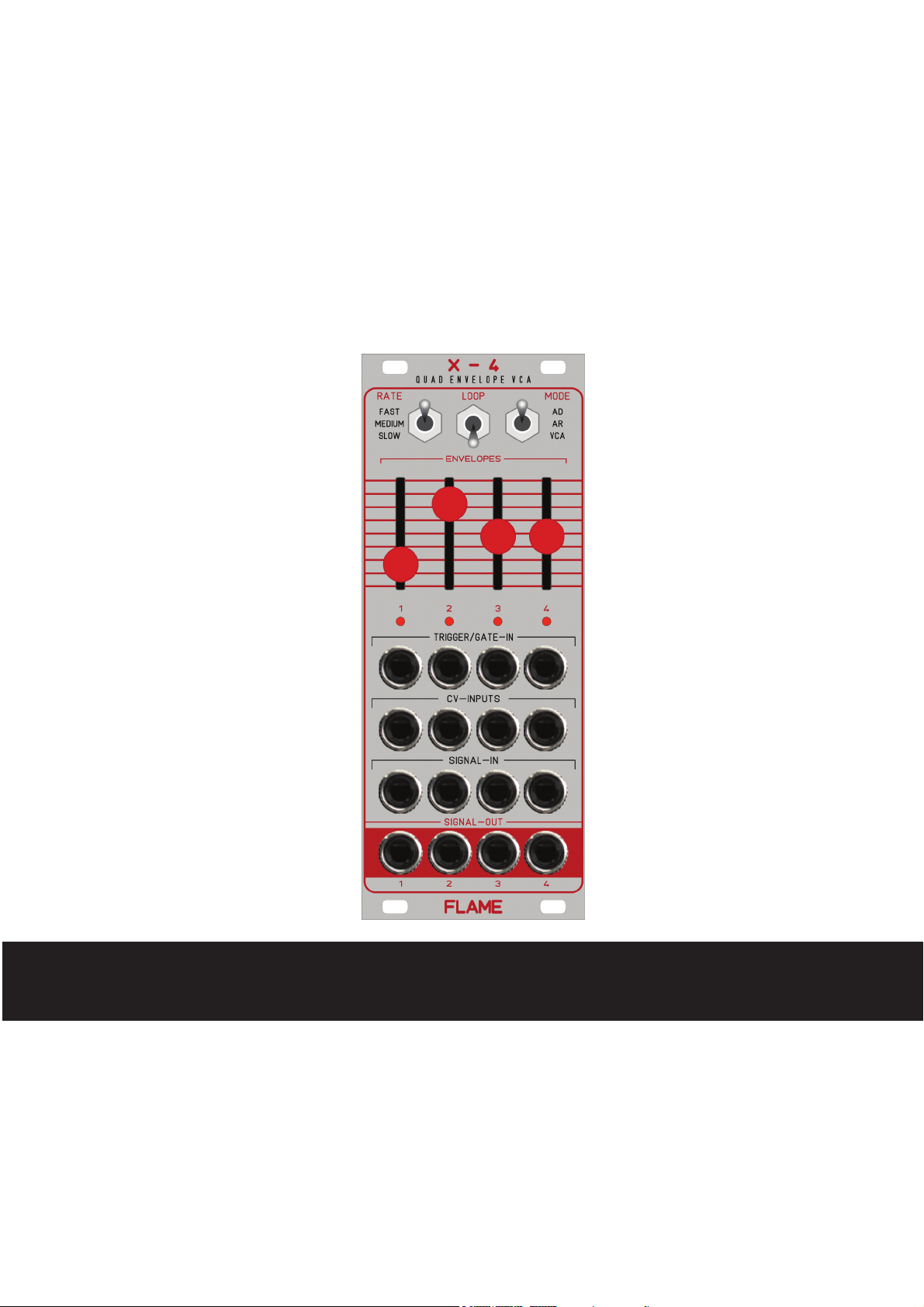
The FLAME "X-4" is a compact, multifunctional quad envelope/VCA module, which combines
four AD/AR envelopes and four separate VCAs in a very small space (10HP). The module is a
supplement for quad VCO's (e.g. FLAME "4VOX") and expands it by four VCAs and envelopes
in the smallest space. Each channel can be used separately as an AD/AR envelope generator
with VCA, or just as a VCA.
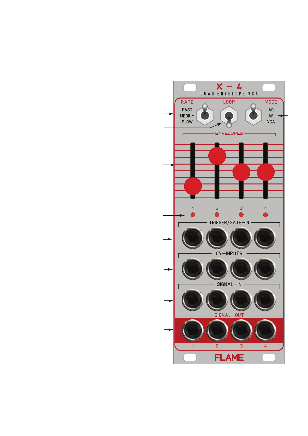
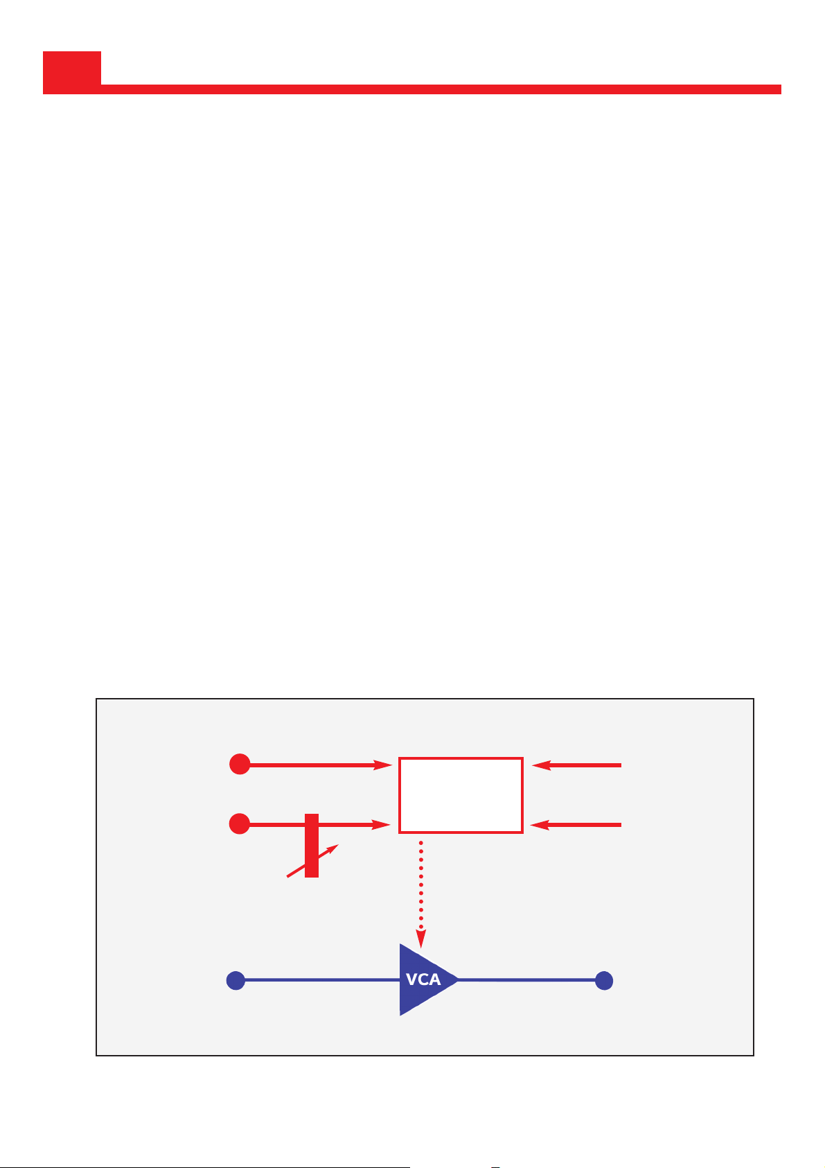
There are 3 operating modes:
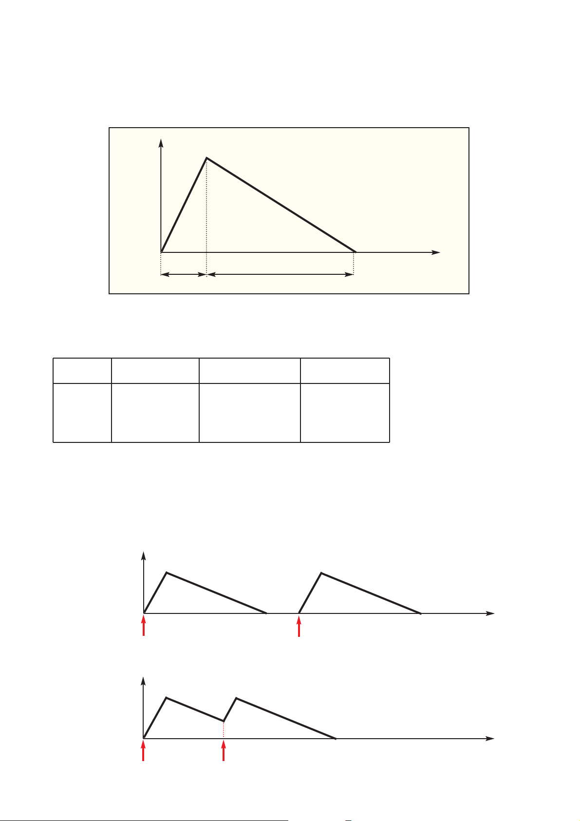
AD: four separate attack/decay envelopes on four VCA channels (oneshot per trigger)
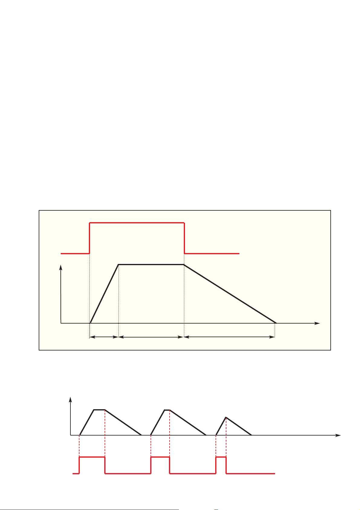
AR: four separate attack/release envelopes on four VCA channels (per gate)
VCA: four CV controllable separate VCAs
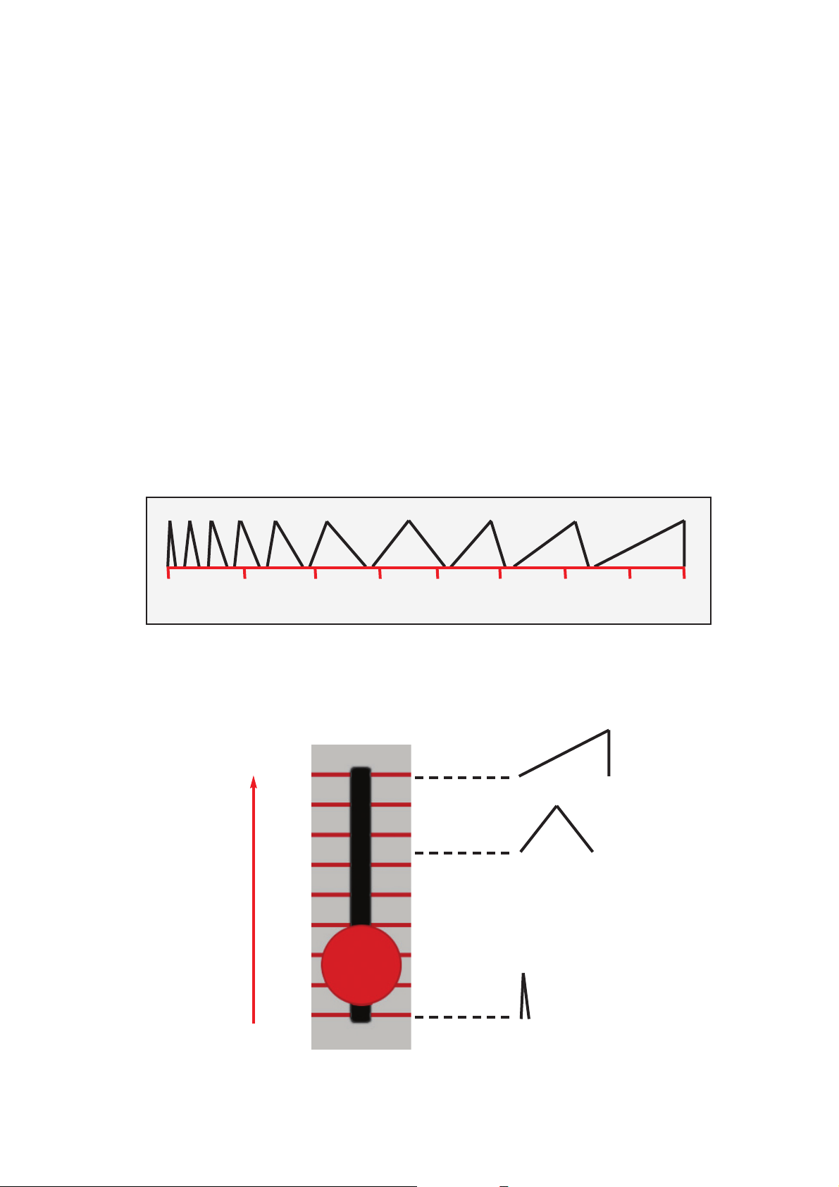
ARATE switch is available for three ranges (1.5ms to 14 seconds). The envelope shape is set
morphing with the sliders (can also be controlled via CV). The envelope can also be looped
(gated AD/AR envelope loop).
3
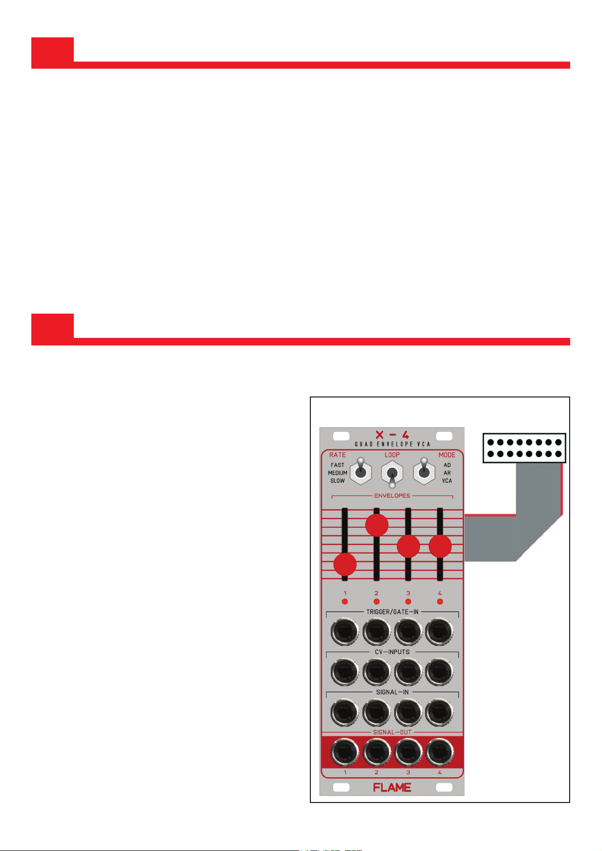
2.1 Connection to the modular system (Doepfer bus)
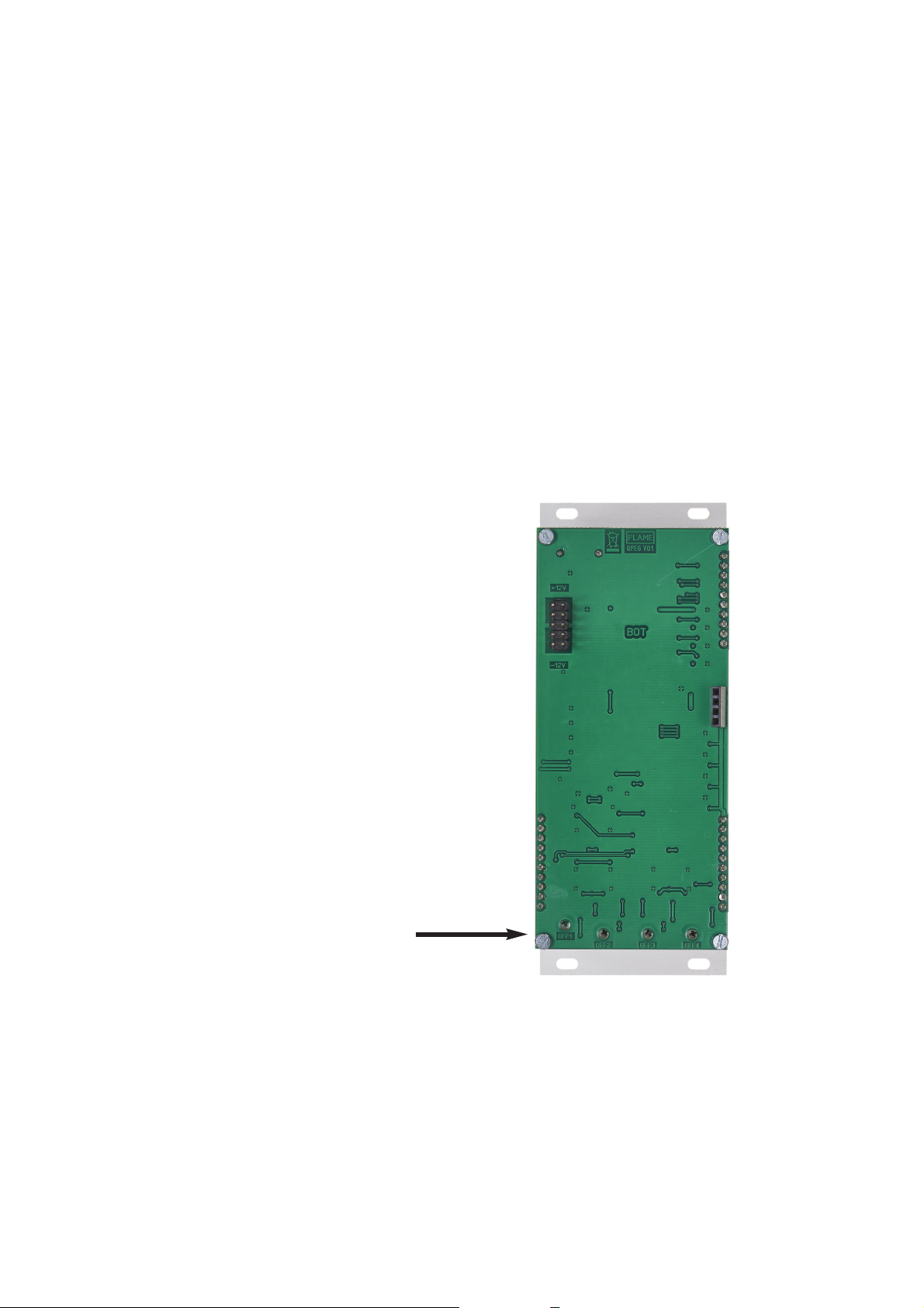
The module is delivered with a connected
ribbon cable for the Doepfer bus. The red
lead marks -12 volt. Connecting the module
please note the right polarity!
If the module is poled accidentally wrong
safety diodes avoid the immediate destruc-
tion of the module but further damages can-
not be excepted.
So please pay attention: Check the con-
nection various times before switching on!
-12V
Ground
Ground
Ground
+12V