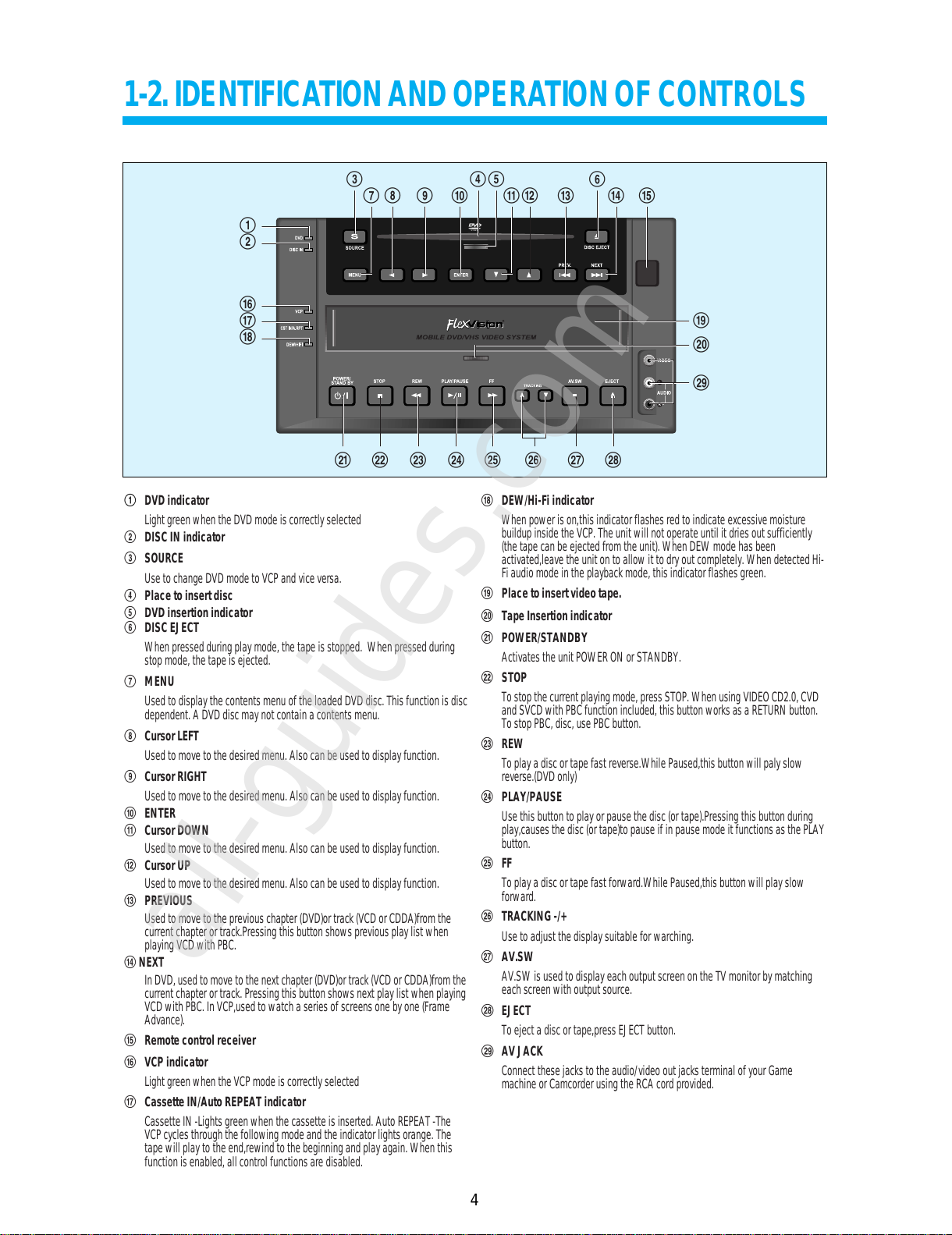
flexvision dvdvcp01 User manual

SERVICE MANUAL
MOBILE DVD-VIDEO PLAYER
DVDVCP01
CAUTION
BEFORE SERVICING THE CHASSIS, READ THE "SAFETY
PRECAUTIONS", IN THIS MANUAL.
All manuals and user guides at all-guides.com
all-guides.com

• Safety Check after Servicing
Examine the area surrounding the repaired location for damage or deterioration. Observe that screws, parts and wires
have been returned to original positions. Afterwards, perform the following tests and confirm the specified values in
order to verify compliance with safety standards.
1. Insulation resistance test
Confirm the specified insulation resistance or greater between power cord plug prongs and externally exposed parts
of the set (RF terminals, antenna terminals, video and audio input and output terminals, microphone jacks, earphone
jacks, etc.). See table below.
2. Dielectric strength test
Confirm specified dielectric strength or greater between power cord plug prongs and exposed accessible parts of the
set (RF terminals, antenna terminals, video and audio input and output terminals, microphone jacks, earphone jacks,
etc.) See table below.
3. Clearance distance
When replacing primary circuit components, confirm
specified clearance distance (d), (d') between soldered
terminals, and between terminals and surrounding
metalic parts. See table below.
Table 1: Rating for selected areas
* Class II model only.
Note: This table is unofficial and for reference only. Be sure to confirm the precise values for your particular country
and locality.
4. Leakage current test
Confirm specified or lower leakage current between B (earth ground, power cord plug prongs) and externally
exposed accessible parts (RF terminals, antenna terminals, video and audio input and output terminals, microphone
jacks, earphone jacks, etc.)
Measuring Method: (Power ON)
Insert load Z between B (earth ground, power cord plug
prongs) and exposed accessible parts. Use and AC
voltmeter to measure across both terminals of load Z.
See figure and following table.
Table 2: Leakage current ratings for selected areas
Note: This table unofficial and for reference only. Be sure to confirm the precise values for your particular country and
locality.
Z
Exposed
accessible
part AC Voltmeter
(high impedance)
Earth Ground
power cord plug prongsB
Fig. 2
AC Line Voltage Region Insulation Dielectric Clearance
Resistance Strength Distance (d), (d')
100V Japan ≥1 MΩ/500 V DC 1kV 1 minute ≥3 mm
110 to 130V USA & – – – 900V 1 minute ≥3.2mm
Canada
* 110 to 130 V Europe ≥10 MΩ/500 V DC 4 kV 1 minute ≥6 mm (d)
200 to 240 V Australia ≥8 mm (d')
(a: Power cord)
Fig. 1
d
Primary circuit terminals
Chassis
d'
a
AC Line Voltage Region Earth Ground
Load Z Leakage Current (i) (B) to:
100V Japan ¡ ≤1m A rms Exposed accessible
parts
110 to 130 V USA & ¡ ≤0.5 m A rms Exposed accessible
Canada parts
¡ ≤0.7 m A peak Antenna earth
110 to 130 V Europe ¡ ≤2 m A dc terminals
200 to 240 V Australia ¡ ≤0.7 m A peak Other terminals
¡ ≤2 m A dc
1k
1.5k
1.5kµF
2k
50k
All manuals and user guides at all-guides.com

TOTAL CONTENTS
1
SECTION 1. GENERAL....................................................................................................................2
SECTION 2. CABINET & MAIN FRAME.........................................................................................6
SECTION 3. ELECTRICAL ............................................................................................................10
All manuals and user guides at all-guides.com

SECTION 1. GENERAL
2
CONTENTS
1-1. SPECIFICATIONS............................................................................................................................3
1-2. IDENTIFICATION AND OPERATION OF CONTROLS...............................................................4
All manuals and user guides at all-guides.com

* Design and specifications subject to change without notice.
1-1. SPECIFICATIONS
3
Power DC 12V Negative Ground
Consumed electricity 24W (supplementary 2.5W)
Weight 5.3kg
Dimension (WxHxD) 250mm x 135mm x 266.5mm
Operative temperature 0°C ~ 45°C
Installation condition Horizontal / Relative humidity under 80%
Signal type NTSC COLOR
VIDEO input 1.0Vp-p unbalanced, RCA JACK
AUDIO input -8.8dBm, RCA JACK
VIDEO output VIDEO output terminal, 1.0Vp-p unbalanced, RCA JACK
AUDIO output Audio output terminal (2 kinds): -7.8dBm(VCP), 2.0Vrms(DVD), RCA JACK
Playable tape Very high density tapes with VHS marks
Playable disc DVD, VIDEO-CD, CD (12mm), CD (8mm), MP3, CD-R, CD-RW, DVD-RW, DVD+RW
Tape speed SP: 33.35mm/s, SLP: 11.12mm/s
Playtime SP: 2hrs, SLP: 6hrs (use of T-120 tape)
VIDEO S/N (VCP) Over 43dB (Standard recording)
Resolution VCP Over 220 lines (Standard recording)
DVD Over 500 lines (DVD Disc PLAY)
AUDIO (VCP) Over 40dB
AUDIO (DVD) 80dB
AUDIO dynamic range 90dB
All manuals and user guides at all-guides.com

1-2. IDENTIFICATION AND OPERATION OF CONTROLS
4
!
#
@
6
7
8
$%
& 1 42 3*
“ ‘ + = Q q W w
( )
^
5
9
0
E
!DVD indicator
Lightgreen whentheDVD modeis correctly selected
@DISC IN indicator
#SOURCE
Useto changeDVDmode toVCPand viceversa.
$Place to insert disc
%DVD insertion indicator
^DISC EJECT
Whenpressed duringplaymode, thetape is stopped. Whenpressed during
stopmode, thetapeis ejected.
&MENU
Usedto displaythecontents menuof the loadedDVD disc.Thisfunction isdisc
dependent.A DVDdiscmay notcontain a contentsmenu.
*Cursor LEFT
Usedto movetothe desiredmenu. Also canbe usedtodisplay function.
(Cursor RIGHT
Usedto movetothe desiredmenu. Also canbe usedtodisplay function.
)ENTER
1Cursor DOWN
Usedto movetothe desiredmenu. Also canbe usedtodisplay function.
2Cursor UP
Usedto movetothe desiredmenu. Also canbe usedtodisplay function.
3PREVIOUS
Usedto movetothe previouschapter (DVD)or track(VCD orCDDA)fromthe
currentchapter ortrack.Pressingthis buttonshows previous playlist when
playingVCD withPBC.
4 NEXT
InDVD, usedtomove tothe next chapter(DVD)or track(VCDor CDDA)fromthe
currentchapter ortrack.Pressing thisbutton shows nextplay listwhenplaying
VCDwith PBC.InVCP,used towatch a seriesof screensoneby one(Frame
Advance).
5 Remote control receiver
6VCP indicator
Lightgreen whentheVCP modeis correctly selected
7Cassette IN/Auto REPEAT indicator
CassetteIN -Lightsgreenwhen thecassette is inserted.Auto REPEAT-The
VCPcycles throughthefollowing modeand the indicatorlights orange.The
tapewill playtothe end,rewindto the beginningand playagain.When this
functionis enabled,allcontrol functionsare disabled.
8DEW/Hi-Fi indicator
Whenpower ison,thisindicator flashesred to indicateexcessive moisture
buildupinside theVCP.The unitwill not operateuntil itdriesout sufficiently
(thetape canbeejected fromthe unit). WhenDEW modehasbeen
activated,leavethe unitonto allowit to dryout completely.Whendetected Hi-
Fiaudio modeinthe playbackmode, this indicatorflashes green.
9Place to insert video tape.
0Tape Insertion indicator
“POWER/STANDBY
Activatesthe unitPOWERON orSTANDBY.
‘STOP
Tostop thecurrentplaying mode,pressSTOP. WhenusingVIDEO CD2.0,CVD
andSVCD withPBCfunction included,thisbutton worksasa RETURNbutton.
Tostop PBC,disc,use PBCbutton.
+REW
Toplay adiscor tapefastreverse.While Paused,thisbuttonwill palyslow
reverse.(DVDonly)
=PLAY/PAUSE
Usethis buttontoplay orpause the disc(or tape).Pressingthisbutton during
play,causesthe disc(ortape)to pauseif in pausemode itfunctionsas thePLAY
button.
QFF
Toplay adiscor tapefastforward.While Paused,thisbuttonwill playslow
forward.
qTRACKING -/+
Useto adjustthedisplay suitablefor warching.
WAV.SW
AV.SWis usedtodisplay eachoutput screen onthe TVmonitorby matching
eachscreen withoutputsource.
w
EJECT
Toeject adiscor tape,pressEJECT button.
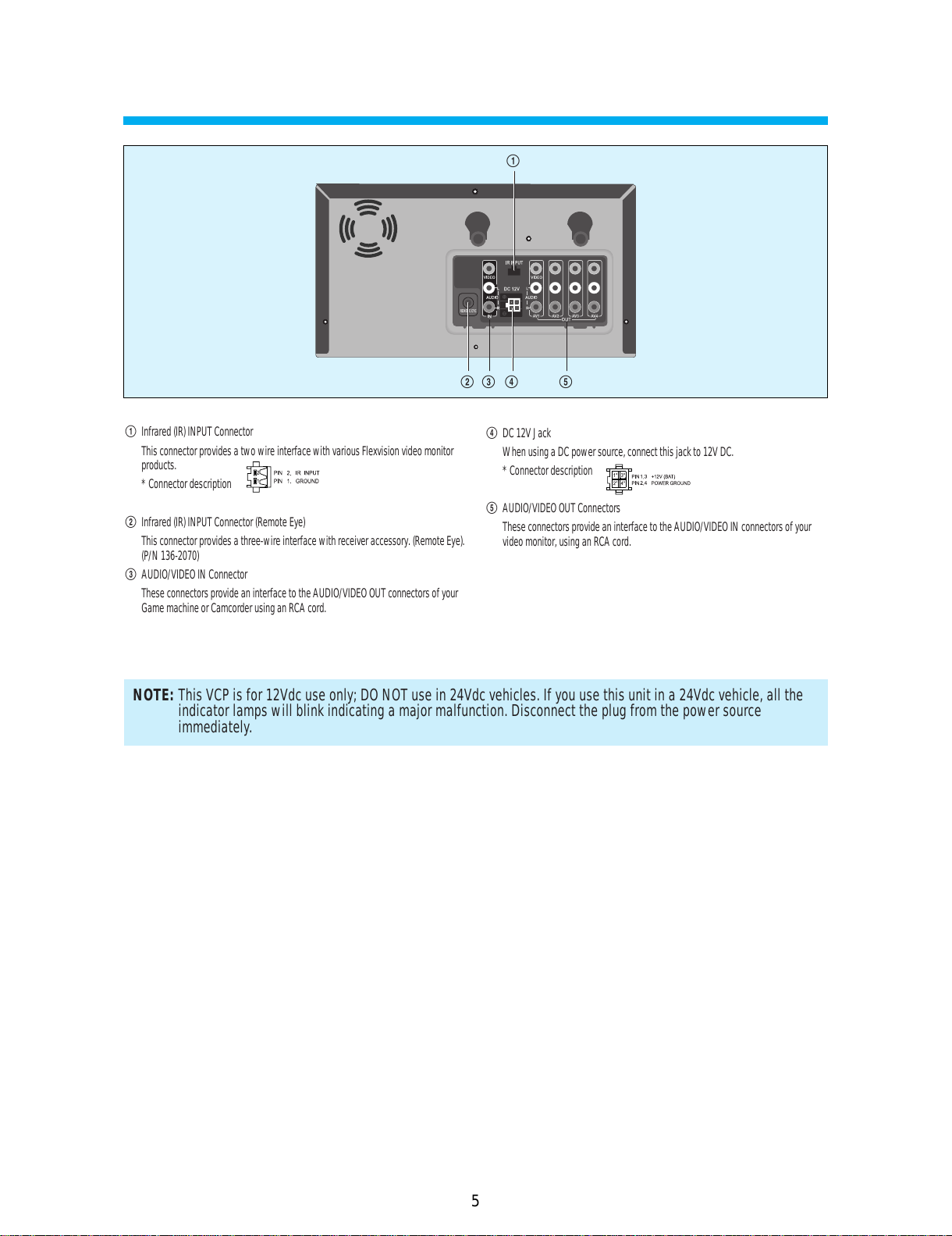
E
AV JACK
Connectthese jackstothe audio/videoout jacks terminalof yourGame
machineor Camcorderusingthe RCAcord provided.
All manuals and user guides at all-guides.com
all-guides.com

5
!
@# $ %
NOTE: This VCP is for 12Vdc use only; DO NOT use in 24Vdc vehicles. If you use this unit in a 24Vdc vehicle, all the
indicator lamps will blink indicating a major malfunction. Disconnect the plug from the power source
immediately.
!Infrared(IR)INPUTConnector
ThisconnectorprovidesatwowireinterfacewithvariousFlexvisionvideomonitor
products.
*Connectordescription
@Infrared(IR)INPUTConnector(RemoteEye)
Thisconnectorprovidesathree-wireinterfacewithreceiveraccessory.(RemoteEye).
(P/N136-2070)
#AUDIO/VIDEOINConnector
TheseconnectorsprovideaninterfacetotheAUDIO/VIDEOOUTconnectorsofyour
GamemachineorCamcorderusinganRCAcord.
$DC12VJack
WhenusingaDCpowersource,connectthisjackto12VDC.
*Connectordescription
%AUDIO/VIDEOOUTConnectors
TheseconnectorsprovideaninterfacetotheAUDIO/VIDEOINconnectorsofyour
videomonitor,usinganRCAcord.
All manuals and user guides at all-guides.com

SECTION 2. CABINET & MAIN FRAME
6
CONTENTS
2-1. EXPLODED VIEW............................................................................................................................7
1) MAIN CHASSIS
2) PANEL FRONT
2-2. PACKING ASSEMBLY....................................................................................................................9
All manuals and user guides at all-guides.com

2-1. EXPLODED VIEW
7
1) MAIN CHASSIS ASS'Y
T1
9
All manuals and user guides at all-guides.com

8
2) PANEL FRONT ASS'Y
9
6
All manuals and user guides at all-guides.com

9
2-2. PACKING ASSEMBLY
All manuals and user guides at all-guides.com
all-guides.com

SECTION 3. ELECTRICAL
10
CONTENTS
3-1. ELECTRICAL ADJUSTMENT......................................................................................................11
1) SERVO-LOGIC CIRCUIT ADJUSTMENT METHOD
3-2. CIRCUIT DIAGRAMS....................................................................................................................12
1) CONNECTION DIAGRAM
2) POWER CIRCUIT DIAGRAM
3) SERVO SYSCON CIRCUIT DIAGRAM
4) VIDEO & AUDIO CIRCUIT DIAGRAM
5) HI-FI CIRCUIT DIAGRAM
6) A/V IN/OUT CIRCUIT DIAGRAM
3-3. COMPONENTS LOCATION GUIDE ON PCB............................................................................18
3-4. ELECTRICAL PARTS LIST..........................................................................................................20
All manuals and user guides at all-guides.com

1) SERVO-LOGIC CIRCUIT ADJUSTMENT METHOD
• VIDEO HEAD SWITCHING POSITION
1) Play back the test tape.
2) Set the oscilloscope in the CHOP mode connect the CH1 to SW pluse PT01 3 PIN the CH2 to VIDEO OUT with CH1
triggering.
3) Press the “REC” button of Jig Remocon to make that playback phase of vertical sync from the rising edge of SW pulse
is 6.5H ±0.5H .
3-1. ELECTRICAL ADJUSTMENT
11
Adj. Location Checking Point Measuring Equipment Mode Test Tape
REC Button(Jig Remocon) PT01 3 PIN Oscilloscope Play DN-2
VIDEO OUT
SWITCHING
SW30Hz
PULSE
VIDEO
OUTPUT
V. SYNC
6.5H±0.5
All manuals and user guides at all-guides.com

3-2. CIRCUIT DIAGRAMS
12
1) LOGIC CIRCUIT DIAGRAM (DV5T711NY)
All manuals and user guides at all-guides.com

13
2) POWER CIRCUIT DIAGRAM (DV5T711NY)
All manuals and user guides at all-guides.com

14
3) SERVO SYSCON CIRCUIT DIAGRAM (DV5T711NY)
All manuals and user guides at all-guides.com
all-guides.com

15
4) VIDEO& AUDIO CIRCUIT DIAGRAM
FM PROCESSING
All manuals and user guides at all-guides.com

16
5) HI-FI CIRCUIT DIAGRAM (DV5T711NY)
All manuals and user guides at all-guides.com

17
6) A/V IN/OUT CIRCUIT DIAGRAM
All manuals and user guides at all-guides.com

3-3. PRINTED CIRCUIT BOARD
18
1) PCB MAIN
All manuals and user guides at all-guides.com
Other manuals for dvdvcp01
2
Table of contents
Other flexvision DVD Player manuals