Flight Systems anemoi 26005-485 User manual

Installation / Operation
Manual
Version: 1.02 © Copyright 2022 RS Flight Systems GmbH

02.04.2022 | V1.02
-2-
Installation / Operation Manual
anemoi
Contents
1. Preface..............................................................................................................................................3
1.1 Limited Warranty......................................................................................................................3
1.2 Sunburned Display Warranty....................................................................................................3
2. System Description...........................................................................................................................4
3. Technical Specifications....................................................................................................................6
3.1 Available Accessories................................................................................................................7
4. Mechanical Installation ....................................................................................................................8
4.1 Display Unit...............................................................................................................................8
4.2 Sensor Unit...............................................................................................................................8
4.3 Temperature sensor installation............................................................................................ 10
4.4 P_TOTAL and P_STATIC Connectors ....................................................................................... 10
4.5 Drawings Display Unit............................................................................................................ 11
4.6 Drawings Sensor Unit ............................................................................................................ 12
5. Electrical Installation ..................................................................................................................... 14
5.1 Display 1 / Display 2 Connector............................................................................................. 15
5.2 GPS NMEA Connector............................................................................................................ 15
5.3 POWER Connector................................................................................................................. 17
5.4 GPS Receiver Connector........................................................................................................ 18
5.5 Wiring Diagram...................................................................................................................... 19
6. Operation....................................................................................................................................... 20
6.1 Startup................................................................................................................................... 20
6.2 Display pages......................................................................................................................... 20
Wind Page...................................................................................................................................... 21
AHRS page ..................................................................................................................................... 21
Data page....................................................................................................................................... 21
6.3 Operation on ground............................................................................................................. 21
6.4 In-Flight operation................................................................................................................. 22
Use of data indicated by anemoi................................................................................................... 22
Data interpretation and reliability................................................................................................. 22
6.5 Setup Menu........................................................................................................................... 23
Calibrate PRS ................................................................................................................................. 24
Rotate Screen ................................................................................................................................ 24
Disable AHRS ................................................................................................................................. 24
Align DOF....................................................................................................................................... 25
Exit................................................................................................................................................. 25
6.6 Errors ..................................................................................................................................... 26
Sensor error................................................................................................................................... 26
-no data-........................................................................................................................................ 26
6.7 Firmware / Software Update................................................................................................. 27
7. Abbreviations and Terms............................................................................................................... 28

Installation / Operation Manual
anemoi
02.04.2022 | V1.02
-3-
1. Preface
Thank you for purchasing an RS Flight Systems anemoi. We are pleased that you have chosen our
product and are confident that it will meet all your expectations. In case of questions or problems with
the unit, feel free to contact:
Service and Support:
Ülis Segelflugbedarf GmbH
Untergasse 1
63688 Gedern | Germany
+49 6045 950100
info@segelflugbedarf24.de
Development and Production:
RS Flight Systems GmbH
Oberer Luessbach 29-31
82335 Berg | Germany
anemoi@rs-flightsystems.com
The anemoi system is designed exclusively for VFR use as an aid to navigation. All information is
presented for reference only. Wind, AHRS and air data are provided as an aid to situation awareness.
Information in this document is subject to change without notice. RS Flight Systems reserve the right
to change or improve their products and to make changes in the content of this material without
obligation to notify any person or organization of such changes or improvements.
1.1 Limited Warranty
This RS Flight Systems product is warranted to be free from defects in materials or workmanship for
two years from the date of purchase. Within this period, RS Flight Systems will, at their sole discretion,
repair or replace any components that fail in normal use. Such repairs or replacement will be made at
no charge to the customer for parts and labor, provided that the customer shall be responsible for any
transportation cost. This warranty does not cover failure due to abuse, misuse, accident, or
unauthorized alterations or repairs. RS Flight Systems displays damaged by direct or magnified sunlight
are not covered under warranty. To obtain warranty service, contact Ülis Segelflugbedarf or RS Flight
Systems directly.
1.2 Sunburned Display Warranty
The anemoi display screen can be damaged or burned by strong sunlight magnified by canopies in
certain positions. We suggest covering your device from direct sunlight, especially if the canopy is
open. anemoi displays damaged by direct or magnified sunlight are not covered under warranty.

02.04.2022 | V1.02
-4-
Installation / Operation Manual
anemoi
2. System Description
The anemoi comprises one sensor and one display unit. Its functionality is as follows:
•Precise indication of wind vector, artificial horizon (AHRS) and flight data (TAS, GS, OAT, FL)
•Stand-alone system architecture
•Sunlight-readable backlit display
•Simple and self-explanatory operation (one push button)
•Minimum installation effort of sensor unit –uninfluenced by magnetic fields
•Compact display unit with versatile installation options
•Simple data transfer and software update via microSD card
•Suitable for 12 VDC aircraft electrical systems
•High level of manufacturing and quality control
•Engineering and production exclusively done in Germany
Figure 2-1: Sensor Unit
Installation / Operation Manual
anemoi
02.04.2022 | V1.02
-5-
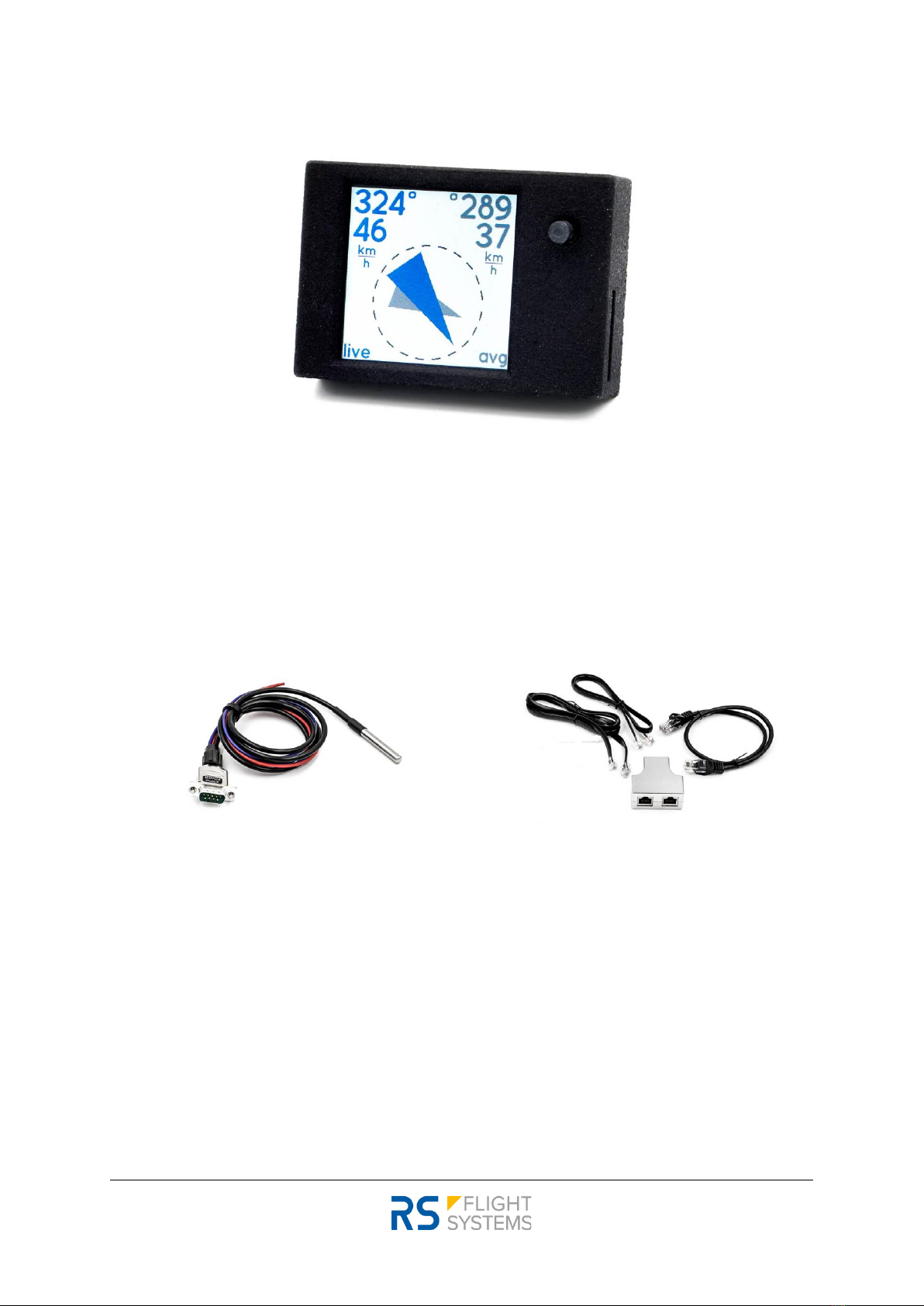
Figure 2-2: Display Unit
Figure 2-3: Wiring Harness Kit
Figure 2-4: Connection Kit

02.04.2022 | V1.02
-6-
Installation / Operation Manual
anemoi
3. Technical Specifications
Sensor Unit
Display Unit
Dimensions
(width, height, depth)
130 x 55 x 35 mm
5.12 x 2.17 x 1.38 in
44 x 30 x 10 mm
1.73 x 1.18 x 0.39 in
Mounting Depth
incl. connectors
70 mm
2.76 in
25 mm
1.00 in
Mounting
4x M4 screws
120 x 40 mm
4.72 x 1.57 in
Taped
Connector Cutout: 14 x 16 mm
0.55 x 0.63 in
Display Cutout: 26 x 26 mm
1.02 x 1.02 in
Total Mass
180 g
0.4 lbs
20 g
0.04 lbs
Housing
Machined aluminum, surface black
anodized
Polyamide 12
Supply Voltage
12 VDC
Power Consumption
100 mA
Display
1.3-inch LCD, 240 x 240 pixels
Firmware Update
microSD card, up to 32 GB, FAT32 formatted
Operating
Temperature Range
-20 to +60 oC
-4 to +140 oF
Operating Altitude
< 7,620 m
< 25,000 ft
Humidity
< 95 %, non-condensing
Table 3-1: Technical Specification

Installation / Operation Manual
anemoi
02.04.2022 | V1.02
-7-
3.1 Available Accessories
Part No.
Name
Description
10-757
anemoi Wind Indication
System
Live wind indication system for aircraft
Kit consists of Sensor Unit and Display Unit
Power supply: 12 VDC
Sensor Unit: 130 x 55 x 35 mm
Display Unit: 44 x 30 x 10 mm
Includes wiring harness 10-752 and connection kit 10-756
26005-455
anemoi Display Unit
Display Unit for anemoi live wind indication system
240 x 240 pixels TFT screen, ultra-bright
Dimensions: 40 x 30 x 10 mm
26005-485
anemoi Sensor Unit
Sensor Unit for anemoi live wind indication
Power supply: 12 VDC
Dimensions: 130 x 55 x 35 mm
10-752
Wiring Harness Kit anemoi
Power wires, length 0.5 m (1.5 ft)
Temperature Sensor, length 1.0 m (3 ft)
10-781
Wiring Harness Kit anemoi
(3m)
Power wires, length 3.0 m (10 ft)
Temperature Sensor, length 3.0 m (10 ft)
10-756
Connection Kit anemoi
Connection Kit for anemoi wind indicator system. Includes:
- Display cable RJ12 0.5 m (1.5 ft)
- NMEA cable RJ45 0.5 m (1.5 ft)
- NMEA RJ45 Y-splitter (1:1)
- 2x T-Reduction Nozzles instrument hose
- Silicone hose 3 x 5 mm (0.12"), length 1.0 m (3 ft)
10-782
Connection Kit anemoi
(3m)
Connection Kit for anemoi wind indicator system. Includes:
- Display cable RJ12 3.0 m (10 ft)
- NMEA cable RJ45 3.0 m (10 ft)
- NMEA RJ45 Y-splitter (1:)
- 2x T-reduction nozzles instrument hose
- Silicone hose 3 x 5 mm (0.12"), length 6.0 m (20 ft)
10-744
Cable RJ12 0,5m
anemoi Display Unit cable
Length: 0.5 m (1.5 ft)
10-778
Cable RJ12 3,0m
anemoi Display Unit cable
Length: 3.0 m (10 ft)
10-745
Cable RJ45 0,5m
NMEA cable anemoi
Length: 0.5 m (1.5 ft)
10-779
Cable RJ45 3,0m
NMEA cable anemoi
Length: 3.0 m (10 ft)
10-746
Y-Adapter RJ45
Y-Adapter for RJ45 cable
1:1 Splitter, shielded
10-747
T-Reduction Nozzle 6-4-6
mm
T-reduction nozzle 6mm-4mm-6mm (0.24"-0.16"-0.24")
Connection of anemoi static pressure and total pressure hose
10-759
Silicone Hose 3x5 mm
Silicone hose, transparent
Inner diameter: 3 mm (0.12”)
10-875
Klixon Circuit Breaker
7277-2-1
Small size and lightweight circuit breaker
Rating: 1 A
10-887
Mounting Adapter anemoi
57mm
anemoi adapter for 57 mm (2.25") instrument panel cutout
13100-177
GPS GNSS Receiver
High precision GPS GNSS receiver
Accepts the signals of up to 50 satellites at the same time
Sensibility max. -162 dBm, IPX6 protection class
Cable length: 1.5 m (5 ft)
Dimensions: 65 x 45 x 22 mm
Table 3-2: Accessories
02.04.2022 | V1.02
-8-
Installation / Operation Manual
anemoi
4. Mechanical Installation
Upon delivery, undertake visual inspection of the package contents for signs of transport damage and
verify the information on the type plate sticker against your order. Do not open the device housing.
For longer storage of the device, select a dry and clean environment. Make sure that the device is not
stored near strong heat sources and that no metal chippings or other dirt can get into the device or its
connectors.
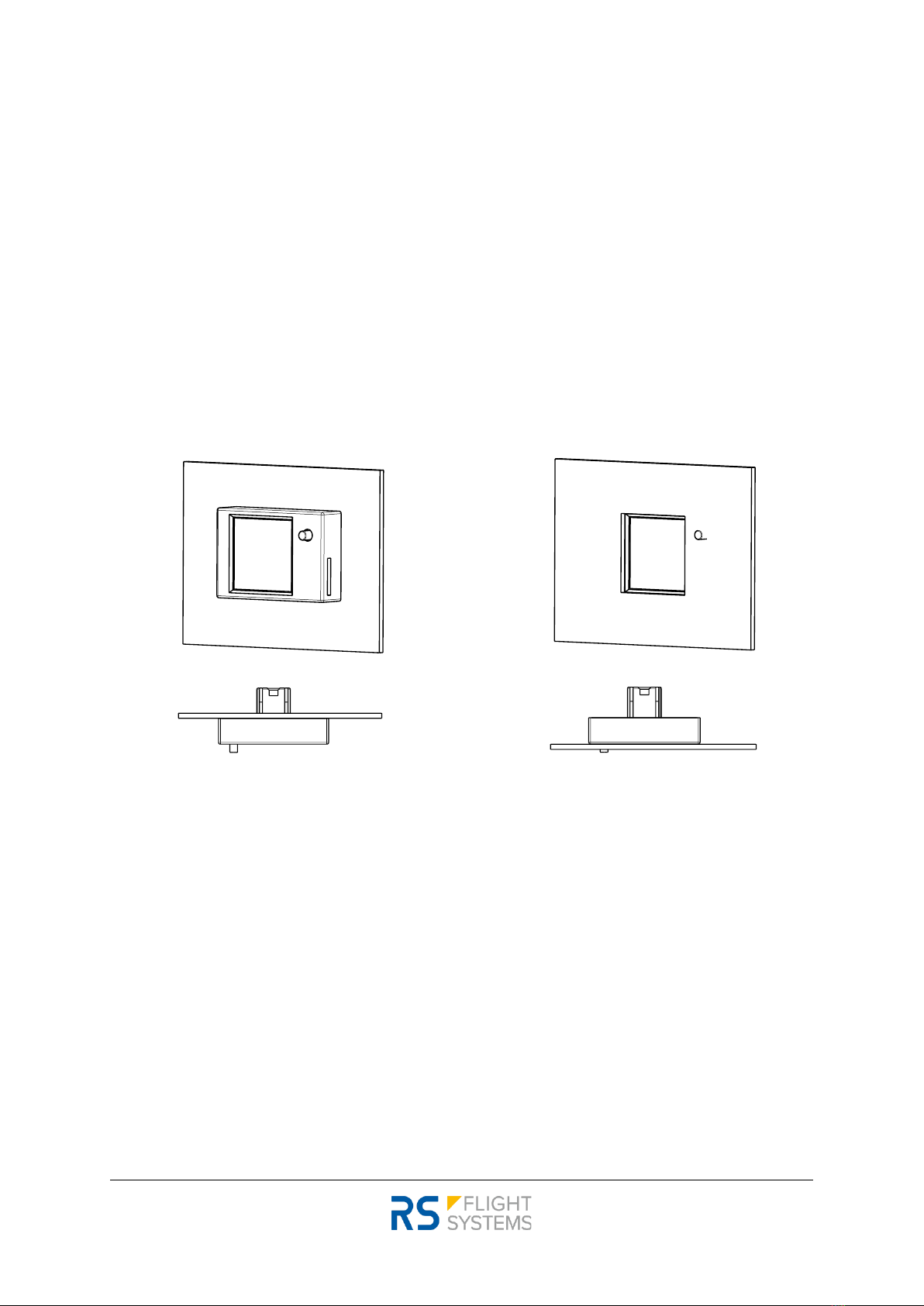
4.1 Display Unit
The display unit is mounted either in front of the instrument panel or behind the instrument panel.
Second variant needs a rectangular cutout (dimensions in Table 3-1). Two mounting examples are
shown in Figure 4-1 and Figure 4-2.
Figure 4-1: Front side mounting
Figure 4-2: Rear side mounting
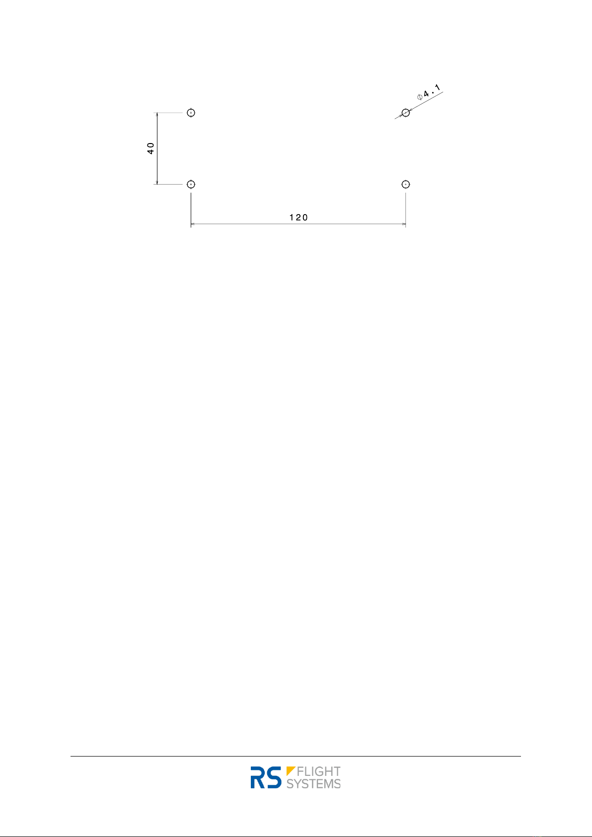
4.2 Sensor Unit
The sensor unit can be mounted behind the instrument panel or in the fuselage. By default, the anemoi
is delivered with a 0.5 m (3.0 ft) wiring harness kit. As an accessory, a 3.0 m (10 ft) wiring harness kit is
available. The sensor unit is mounted with 4x M4 screws. The screw hole positions can be taken from
Figure 4-9.
The mounting position of the sensor unit is shown in Figure 4-3.
Installation / Operation Manual
anemoi
02.04.2022 | V1.02
-9-
Figure 4-3: Mounting cutout sensor unit
The sensor unit needs to be aligned with the aircraft axes by the following margins:
- Yaw axis: +-1°. Misalignment leads to inaccurate wind indication during longer straight flight
segments without moderate changes in airspeed and heading.
- Roll axis: +- 3°. Misalignment leads to permanent offset of the roll angle indicated by the artificial
horizon (AHRS), and potentially falsifies wind indication during longer straight flight segments.
- Pitch axis: +-7°. Alignment can be adjusted and chosen within a relatively wide-angle range with
no noticeable effect on wind indication. The mounting pitch attitude of the sensor unit will be
indicated as “zero pitch”on the artificial horizon (AHRS).
The sensor unit must always be mounted so that the labeled side of the device is “up”. A vertical
mounting is not possible.
The sensor unit can be mounted in four different yaw orientations, indicated as A, B, C, D on the top
side of the sensor unit. If the sensor unit is installed with direction A pointing in the DOF (direction of
flight) no further action is required upon installation. If the sensor unit is installed in the directions of
B/C/D, the DOF must be set in the menu once after installation, as explained in chapter 6.3: Setup
Menu under “Align DOF”.
Three-dimensional CAD-models of the units and the cutout of the display unit are available at the RS
Flight Systems website.
As waste heat is dissipated via free convection, leave at least a 5 mm gap from the aluminum surfaces
to any other object. Forced cooling is not necessary.
The installation must be in accordance with the appropriate guidelines approved by the respective
aviation authority. The person installing the device is responsible for compliance with all applicable
legislation.

02.04.2022 | V1.02
-10-
Installation / Operation Manual
anemoi
4.3 Temperature sensor installation
It is recommended to install the temperature probe as closely to outside air temperature (OAT) as
practically possible, e. g. inside the nose tip or in the front air vent of the aircraft.
Errors in temperature measurement (usually, too warm measurement due to heating from cockpit
systems) can have an impact on the airspeed calibration and therefore negatively influence wind
calculation. However, the system’s sensitivity to temperature errors is quite low, and the anemoi
software is even capable of adjusting to permanent temperature measurement offsets within the first
15 minutes after takeoff. Nevertheless, good temperature measurement is necessary for ideal
performance of the wind indication.
4.4 P_TOTAL and P_STATIC Connectors
P_TOTAL must be connected with the total pressure tube, P_STATIC with the static pressure tube. The
pressure connectors and pressure tubes need to be properly sealed as leakage leads to errors in the
external airspeed indicator and altimeter. During pre-flight check both instruments need to be checked
for their proper functionality.
Installation / Operation Manual
anemoi
02.04.2022 | V1.02
-11-
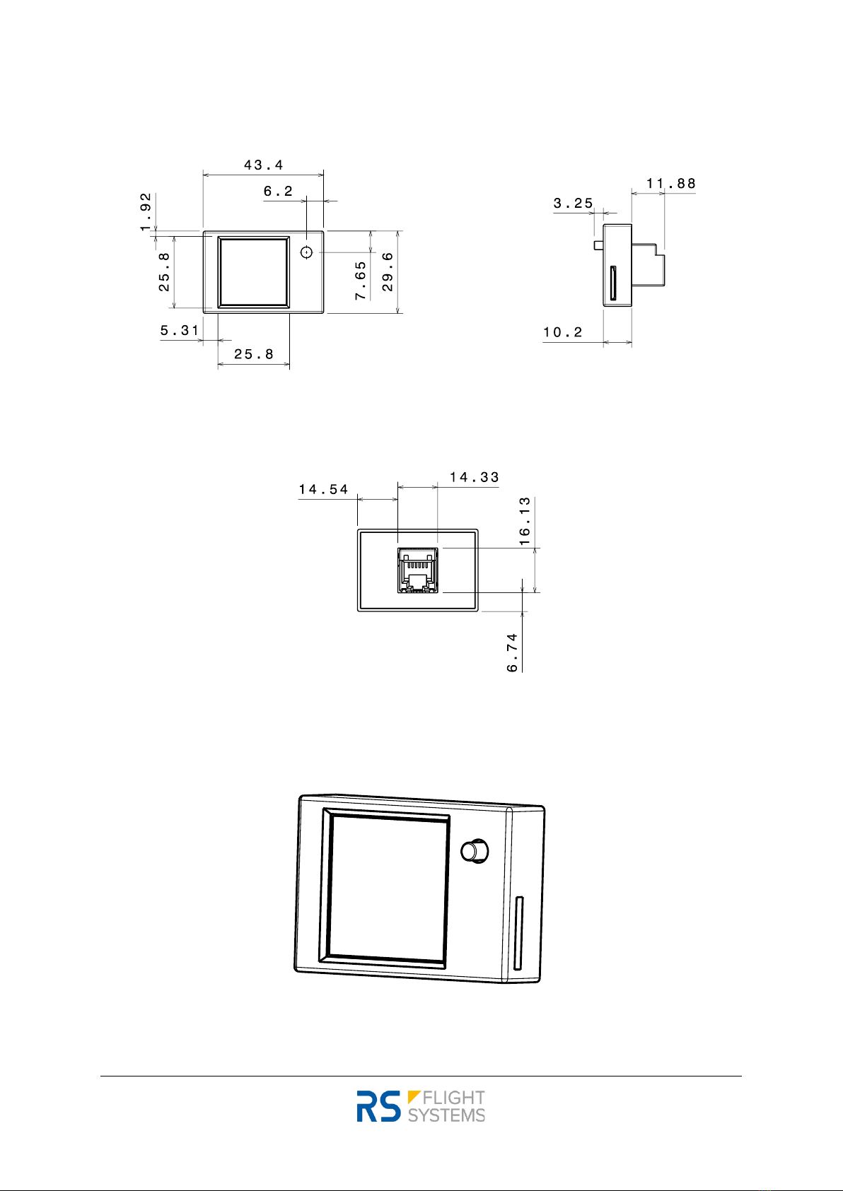
4.5 Drawings Display Unit
Figure 4-4: Display unit (front view / side view)
Figure 4-5: Display unit (rear view)
Figure 4-6: Display unit (isometric view)

02.04.2022 | V1.02
-12-
Installation / Operation Manual
anemoi
4.6 Drawings Sensor Unit
Figure 4-7: Sensor unit (isometric view)
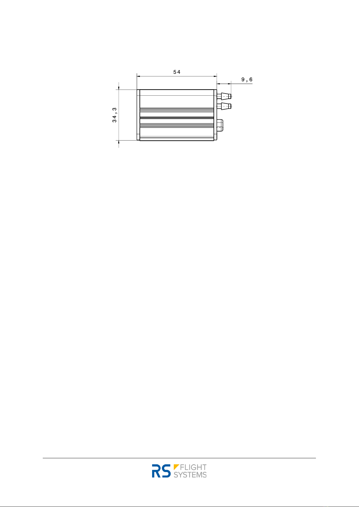
Figure 4-8: Sensor unit (front view)
Figure 4-9: Sensor unit (top view)
Installation / Operation Manual
anemoi
02.04.2022 | V1.02
-13-
Figure 4-10: Sensor unit (side view)

02.04.2022 | V1.02
-14-
Installation / Operation Manual
anemoi
5. Electrical Installation
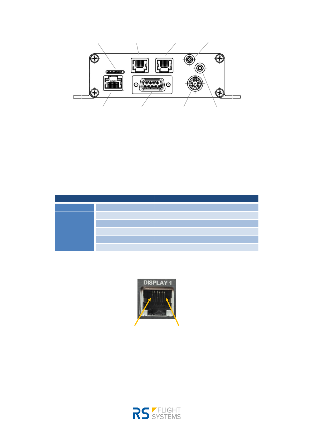
The sensor unit has six electrical connectors and two pressure connectors on the front side. The front
side of the sensor unit is shown in Figure 5-1. Label, type of connector and usage are listed in Table
5-1. Before powering up the unit for the first time, carefully check your wiring.
There is one microSD slot to update the firmware, one RJ45 connector to import GPS data from the
NMEA output. There is also an optional DIN-style connector for an external GPS receiver to import GPS
data. The P/N of the mating GPS receiver is listed in Table 3-2. Two RJ12 connectors transmit data to
the external displays. The D-SUB Power connector is the main connector to power up anemoi. As
shown in the pinout, see Table 5-1 below, D-SUB has power input and an external temperature sensor
wired to it.
GPS data can be provided by a GPS receiver or a device with NMEA output. Make sure that only one is
connected to the sensor unit. Never plug in both, NMEA output and GPS receiver, simultaneously.
If there is an NMEA output device: make sure to use the RJ45 splitter to split up the power supply and
the data lines. The RJ45 data cable is connected directly to the sensor unit in the GPS NMEA slot. The
RJ45 power cable is connected to the default NMEA output power source.
If there is no NMEA output device: plug in the GPS cable in the GPS receiver slot. Place the GPS receiver
in a spot where it has maximum optical visibility of the sky, e. g. the glare shield on top of the
instrument panel. Poor GPS reception has a negative impact on the operation of the unit. It impairs
the accuracy of the wind vector and of the ground speed data.
Label
Connector Type
Usage
“DISPLAY 1”
RJ12 (female 6-pin)
External Display
“DISPLAY 2”
RJ12 (female 6-pin)
External Display
“P STATIC”
Tube
Static Pressure
“P TOTAL”
Tube
Total Pressure
“POWER”
DB9S (female 9-pin D-Sub)
Power Supply and Temperature Sensor
“GPS RECEIVER”
Female Mini-DIN 6
GPS
“GPS NMEA”
RJ45 (female 8-pin)
GPS
”MICRO SD”
MICRO SD
Firmware Upgrade
Table 5-1: Connector overview
Installation / Operation Manual
anemoi
02.04.2022 | V1.02
-15-
Figure 5-1: Sensor Unit Front View
5.1 Display 1 / Display 2 Connector
Displays 1 and 2 use a standard RJ12 connector (6P/6C). Pins 1 and 2 are supplied with +5 VDC, Pins 5
and 6 are ground. The extended pin allocation is shown in Table 5-2.
Pin Number
Signal Name
Function
1
PWR_OUT
Display Unit Power Supply, +5 VDC
2
PWR_OUT
Display Unit Power Supply, +5 VDC
3
BUTTON
Display Unit Button line
4
DATA
Display Unit Data line
5
DISPLAY_GND
Display Unit Power Supply Ground
6
DISPLAY_GND
Display Unit Power Supply Ground
Table 5-2: Pin allocation Display 1 / Display 2
Figure 5-2: Display Connector pin allocation
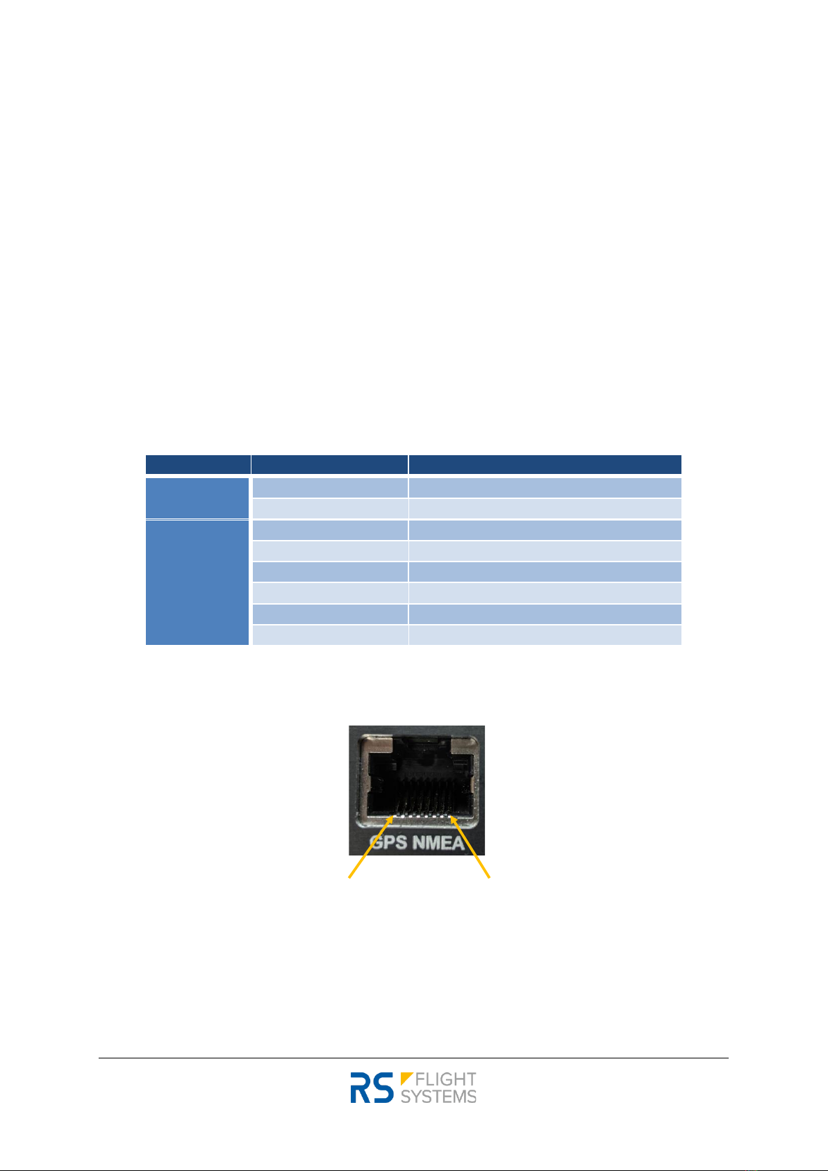
5.2 GPS NMEA Connector
If an NMEA RS-232 output device is used as a GPS source, in most installations no specific action
beyond simple plug-in of the RJ45 connector is required.
DISPLAY 1 DISPLAY 2MICRO SD
GNSS NMEA POWER GNSS ANTENNA
P TOTAL
P STATIC
1 2 3 4 5 6
02.04.2022 | V1.02
-16-
Installation / Operation Manual
anemoi
-The RJ45 connector has the standard IGC pinout, however only the pins Rx (anemoi receives
data) and GND are actively used. anemoi does not supply or consume power nor send data
(Tx) via the NMEA RJ45 connector.
-If anemoi is operated in parallel with other devices on the RS-232 NMEA bus, a 1:1 Y-
Adapter can be used to split the signal. The P/N of the 1:1 Y-Adapter is listed in Table 3-2. As
anemoi merely receives but does not send data on the Tx line, it is not required to detach
the Tx line from anemoi to avoid multiple devices sending on the same line.
-Make sure that the NMEA sentence “GPRMC”(standard navigation data) is included in the
output of the source device. In most cases no action is actively required to ensure sending of
this sentence, as it is the most fundamental content in the NMEA protocol.
-The Baud rate of the RS-232 NMEA data stream must be one of the following: 9600, 19200,
38400, 57600, 115200 bps. If this is the case, anemoi will automatically adjust to the correct
Baud rate.
The extended pin allocation of the RJ45 GPS NMEA connector is shown in Table 5-3. A picture with
the pin numbering is shown in Figure 5-3.
Pin Number
Signal Name
Function
1
-
do not connect
2
-
do not connect
3
-
do not connect
4
-
do not connect
5
NMEA_DATA_RX
NMEA anemoi RX Data Line
6
-
-
7
NMEA_GND
NMEA Device Power Supply Ground
8
NMEA_GND
NMEA Device Power Supply Ground
Table 5-3: Pin out GPS NMEA connector
Figure 5-3: GPS NMEA Connector pin allocation
1 2 3 4 5 6 7 8
Installation / Operation Manual
anemoi
02.04.2022 | V1.02
-17-
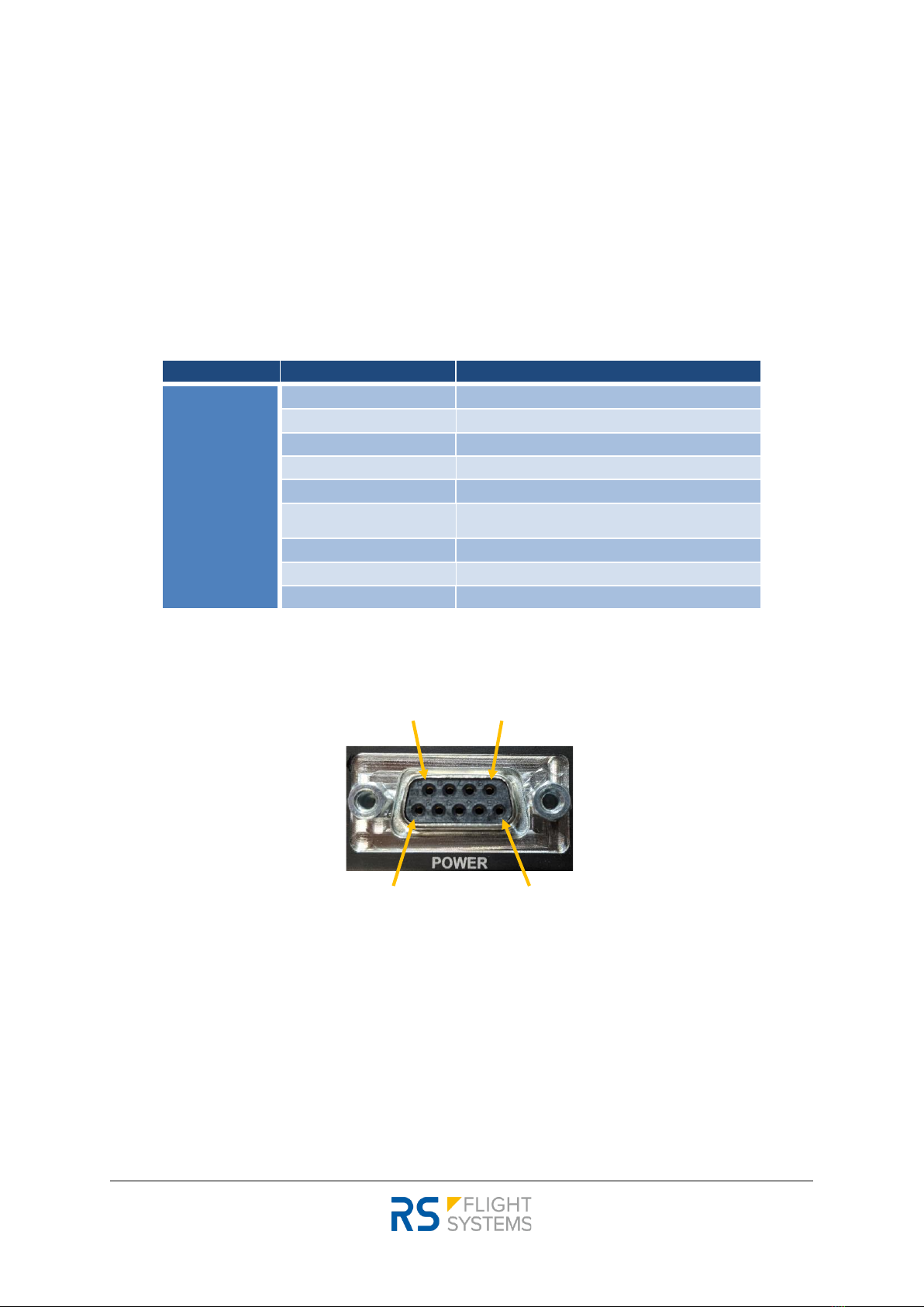
5.3 POWER Connector
The sensor unit uses a standard D-SUB 9 connector. Pin 1 is supplied with +12 VDC, Pin 5 is ground.
Pin must be fused with a 1.0 A circuit breaker. The P/N of the circuit breaker is listed in Table 3-2. The
anemoi is delivered with a prewired power connector harness, including two power cables and the
temperature sensor.
The extended pin allocation is shown in Table 5-4. A picture of the connector can be seen in Figure
5-4. A picture with the pin numbering is shown in Figure 5-4.
Pin Number
Signal Name
Function
1
PWR_IN
Positive Power Supply, +12 VDC
2
DEBUG
Internal Debugging, DO NOT CONNECT
3
DEBUG
Internal Debugging, DO NOT CONNECT
4
-
do not connect
5
AC_GND
Aircraft Ground
6
TEMP_PWR
Temperature Sensor Positive Power Supply,
+5 VDC
7
TEMP_DATA
Temperature Sensor Data Line
8
TEMP_GND
Temperature Sensor Ground
9
DEBUG_GND
Internal Debugging GND, DO NOT CONNECT
Table 5-4: Pin out Power Connector
Figure 5-4: Power Connector pin allocation
6 7 8 9
1 2 3 4 5
02.04.2022 | V1.02
-18-
Installation / Operation Manual
anemoi
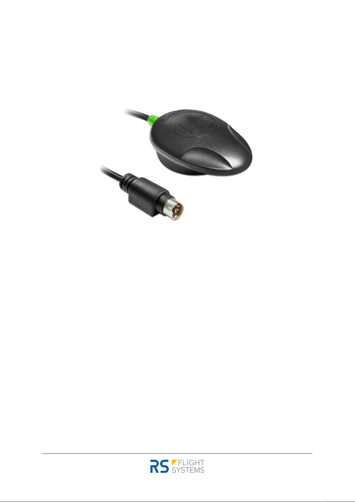
5.4 GPS Receiver Connector
The anemoi GPS receiver has a mating connector for the GPS port. The P/N of the receiver is listed in
Table 3-2. The anemoi GPS receiver can be used, if no NMEA source is available in the aircraft.
Figure 5-5: GPS receiver
Installation / Operation Manual
anemoi
02.04.2022 | V1.02
-19-
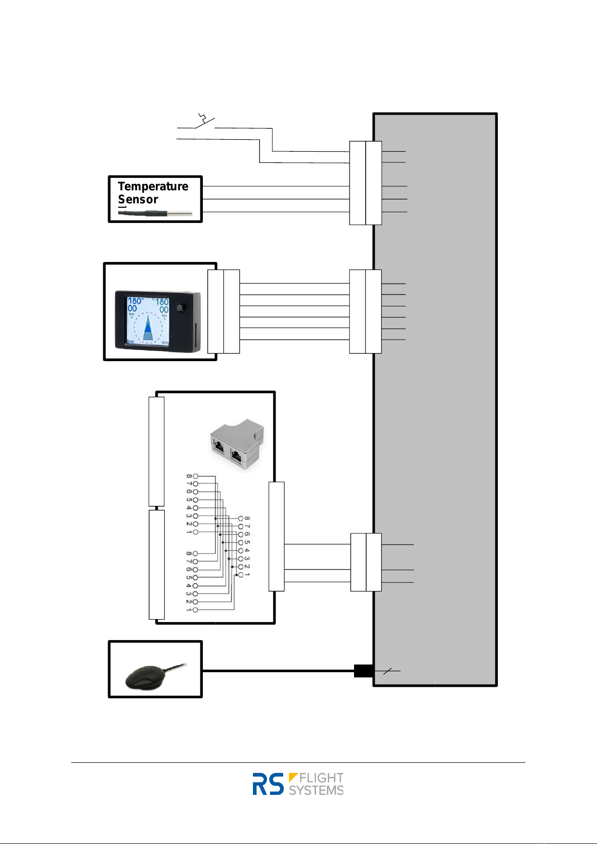
5.5 Wiring Diagram
Figure 5-6: Wiring Diagram
1.0 A anemoi Sensor Unit
PWR_IN
AC_GND
Temperature
Sensor
Main Bus
Aircraft GND
Display Unit
RJ45 Y-Splitter
GNSS Antenna
TEMP_PWR
TEMP_DATA
TEMP_GND
NMEA_RX
GPS
1
5
6
7
8
PWR_OUT
PWR_OUT
BUTTON
DATA
DISPLAY_GND
DISPLAY_GND
POWER
GNSS ANTENNA
GPS NMEA
DISPLAY 1/2
5
7
8
5
7
8
1
2
3
4
5
6
1
5
6
7
8
1
2
3
4
5
6
1
2
3
4
5
6
1
2
3
4
5
6
7
8
1
2
3
4
5
6
7
8
NMEA_GND
NMEA_GND
1
2
3
4
5
6
7
8
yellow
black
red
red
blue
1
2
3
4
5
6

02.04.2022 | V1.02
-20-
Installation / Operation Manual
anemoi
6. Operation
In this chapter operational procedures for the anemoi are described.
6.1 Startup
The anemoi starts up as soon as the required supply voltage is provided. The subsequent startup
screen is displayed for 2 seconds. The startup page is shown in Figure 6-1. The startup page gives details
about the current software version while internal testing routines are performed to ensure correct
operation of all electronic components and sensors (TMP, GPS, PRS, IMU). The color
(green/yellow/red), see Table 6-1 for explanation, indicates the state of the respective sensor.
Figure 6-1: Startup screen
IMU, PRS, TMP
GPS
Not ready
No NMEA data
-
NMEA data, no GPS
Ready
GPS ready
Table 6-1: Sensor health indication at system start
6.2 Display pages
Upon completion of the startup process, the display shows the operational pages. The push button
(short push and release) can be used to switch between the three available pages: Wind page, AHRS
page, and Data page.
IMU PRS TMP GPS
1.0 | 1.0
Inertial
Measurement
Unit health state
Pressure sensor
health state
Temperature
Sensor health
state
GPS (NMEA input)
health state
Sensor Unit
software version
Display Unit
software version
Table of contents


