Flintec FRD-45 BL User manual
... the right weigh
FRD-45 BL Manual page 1 of 8
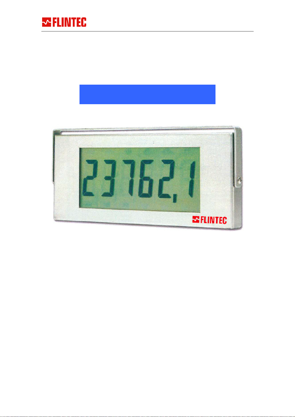
45 mm LCD Numerical Display
MANUAL
Release 10.11.2006
This manual was created with special care on the technical content and the correct
verbalisation. However, as a matter of principle Flintec GmbH will not take
responsibility for any damage caused by missing or wrong informations
FRD
–
45 BL

... the right weigh
FRD-45 BL Manual page 2 of 8
1. SAFETY INFORMATION .................................................................. 2
2. CHARACTERISTICS......................................................................... 3
DISPLAY.............................................................................................................. 3
MECHANICAL.......................................................................................................3
SAFETY & ENVIRONMENT....................................................................................3
ELECTRONICS .....................................................................................................4
3. OPERATION NOTES........................................................................ 5
INSTALLATION NOTES.........................................................................................5
NORMAL BEHAVIOUR...........................................................................................5
STANDARD PROTOCOL DESCRIPTION .................................................................. 5
PROGRAMMING OPERATIONAL PARAMETERS .......................................................6
4. SERVICE AND CONTACT INFORMATION ........................................ 8
1. Safety Information
All products of this series are developed, manufactured and tested in accordance with
the applicable industry safety standards. If these products are properly installed,
operated and maintained according to the applicable technical instructions, drawings
and specifications, no hazard exists in the normal and intended use of these products.
General Safety Guidelines
The following general safety guidelines apply to all Flintec - products:
All applicable safety and accident prevention recommendations must be
observed (VDE 0100 and VDE 0113).
All installation, start-up and maintenance work must be carried out by qualified
service personnel only.
An easily accessible power outlet must be located close by for devices equipped
with a main power cord and plug.
An easily accessible MAIN POWER ON/OFF switch must be provided for
equipment with permanent electrical connections.

... the right weigh
FRD-45 BL Manual page 3 of 8
2. Characteristics
DISPLAY
Character Height 45 mm
Number of digits 6
Resolution Seven segments plus colon and decimal point
Technology Transflective positive TN LCD
Designator Permanent label sticker (eg. kg, t, rpm,°C, pH)
Backlight Yes; amber LEDs
MECHANICAL
Size casing 244 mm x 109 mm x 22 mm (w x h x d) (w/o connector)
Size inc. bracket 256 mm x 118 mm x 22 mm (w x h x d)
Materials 0,7 mm stainless steel, AR coated front
Protection IP40; optional sealed electronics, guaranteed for unprotected.
outdoor use and hose down washing (IP65).
Operating temp. -10°C to +60°C (intermittent up to +70°C)
Weight Weight 0,8 kg net; 1 kg shipping (IP65 1,0 kg net; 1,2 kg
shipping)
Display Dimensions
SAFETY & ENVIRONMENT
Health and Safety The unit contains negligible amounts of combustible materials,
and will not support a fire. No toxic or hazardous material is
used.
Fulfills RoHS directive (lead free) from november 2005 (= from
serial No 1000 on)
... the right weigh
FRD-45 BL Manual page 4 of 8
ELECTRONICS
Interface, standard RS-232, RS-422/RS-485 input and 20 mA Current Loop field
selectable
Baud rates: 1200-19200 with 7 or 8 databits;
even, odd or no parity
Optional interface Analoge inputs, fieldbus interfaces, counters
Power requirements 24 VDC typically 60 mA with backlight
or 12 VDC typically 5 mA without backlight
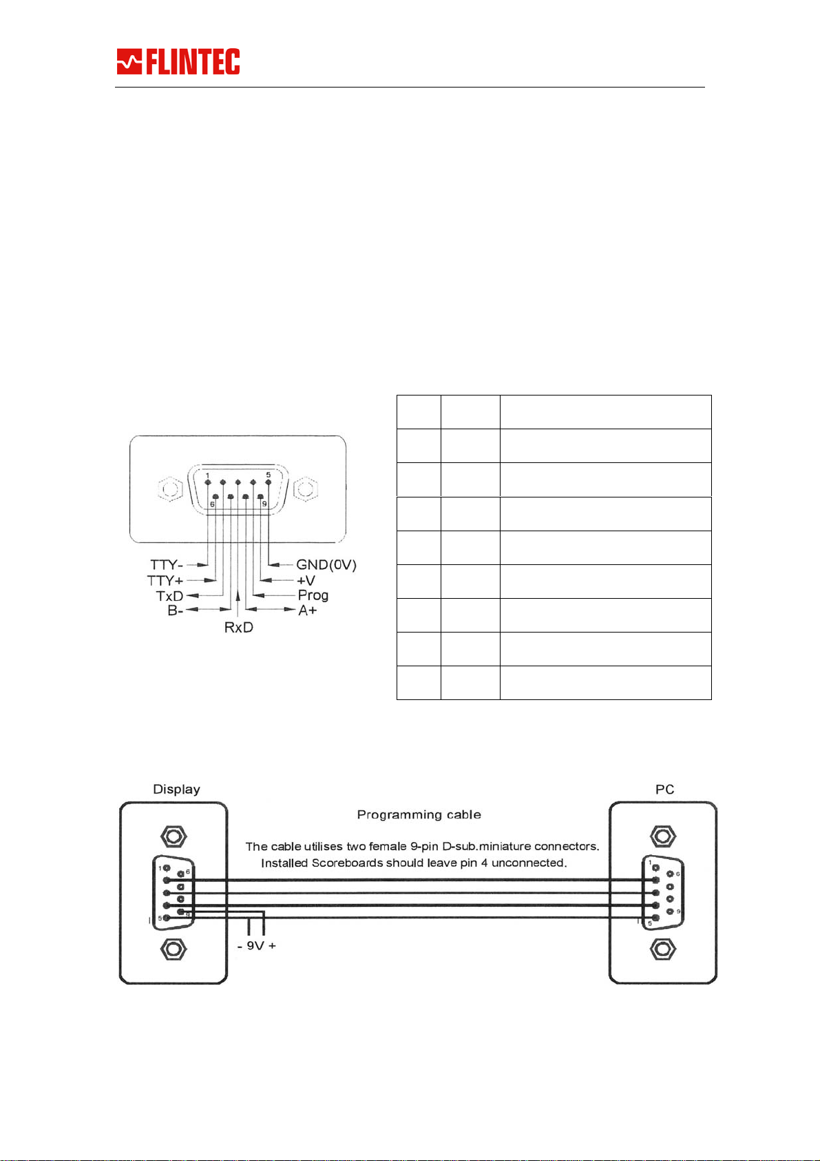
Termination 9-pin male d-sub on the back; mating connector is DB9F
PIN Assignement
Programming Cable PIN Assignement
Pin 1 TTY- Input negative 20 mA
Pin 2 TxD Output connects to RxD on RS-
232 Host
Pin 3 RxD Input connects to TxD on RS-
232 Host
Pin 4 Prog Input Programming pin
Pin 5 0 V GND on External Power and RS-
232 Host
Pin 6 TTY+ Input positive 20 mA
Pin 7 B- I/O connects to RS-485/422
sender/receiver
Pin 8 A+ I/O connects to RS-485/422
sender/receiver
Pin 9 +V DC Connects to External Power

... the right weigh
FRD-45 BL Manual page 5 of 8
3. Operation Notes
INSTALLATION NOTES
To comply with various safety and conformance rulings, the system must be properly
grounded. The Scoreboard itself needs to be connected to safety earth, and the
connector should be firmly mated and fixed by use of fixing screws.
When power is applied, the display should respond by a sequence of control messages:
Project number, version number, baud rate and address. After the short start-up
formality, display is blanked. If this sequence is missing, check power source and
connections. The voltage present at the pins on the Scoreboard D-sub should be stable
between 8 and 28 Vdc.
NORMAL BEHAVIOUR
When power is applied, the Scoreboard will go through a sequence of initialisation. By
carefully looking at the display, you will be presented the following data:
888888 All segments are on, then off to verify correct operations
002.022 is the project and program version for the Scoreboard
022 repeats the S/W version number
C:9600 indicates the current baud rate setting
A.00 is the address of the display (normally set to 00 if disabled)
After initialisation, the Scoreboard will blank with all decimal points activated. This is
the default 'waiting screen' indicating that it is awaiting a valid message.
If the set-up of the RS property holds a string, the Scoreboard will transmit characters
to the host instrument requesting a message. This will be done repeatedly with
intervals of 1 second if no valid message has been received.
Note that reducing the voltage supplied below 20V will turn off backlight and reduce
current consumption. The operation will otherwise be as normal.
STANDARD PROTOCOL DESCRIPTION
A lot of different protocol schemes may be programmed, and the following text only
describes the factory default setup.
As a serial display, the message format handled is based on the parameter setting that
defines valid and essential data. The data displayed is replaced each time a valid new
message is received. Timeout function may auto blank the display after a preset
number of seconds.
<STX>data<CR> where <STX>=ASCII 02d, <CR>=ASCII 13d
data includes minus sign (-), decimal point (represented by '.' or','), leading blanks
or zeros.
Addressing Control
<SOH> AA <STX> will select display AA (00 to 99). 00 will broadcast to all connected
displays. Addressing is used relatively seldom.

... the right weigh
FRD-45 BL Manual page 6 of 8
PROGRAMMING OPERATIONAL PARAMETERS
The PROG Signal (pin 4) will force the display into Programming Mode when high. The
display will show "Programming" and only simple configure commands will be accepted
at 9600,8,N,1. Before and after programming sequence, communication is set to the
selected speed Note that the PROG pin should remain low or unconnected (inactive)
during normal operation. Do not allow unconnected leads to the Prog Pin during
normal operations.
Available commands
SS [enter] list all parameter settings
?? [enter] list all available commands
VV [enter] list software number and version
CC=1200 [enter] set communication speed 1200-19200
PP=N [enter] set parity N,E,0
AA=01 [enter] set address 00-99. (00 means inactive)
PS PS=02 [enter] set Protocol Start character (0=not used)
PE PE=13 [enter] set Protocol End character
TO TO=05 [enter] set TimeOut seconds (0 means not used)
TI TI=03 [enter] set Ignore Characters after start
TL TL=07 [enter] set Text Length number of characters
RS RS=send [enter] set Request String (^a for sending ascii 01)
SP SP=02 [enter] set Sign Byte Position (0 for not used)
SB SB=02 [enter] set Sign Bit position in Sign Byte (0 to 8)
FT FT=kg [enter] set max 3 character trailing text
BP BP=5 [enter] set Control Byte Position (0=not used)
BM BM=07 [enter] set Control Byte Bit Mask (0/255=not used)
BB BB=06 [enter] set Control Byte Compare Byte
PP PP=0 [enter] Particular Protocol (0=normal)
DL DL=6 [enter] set Physical Display Length (6=normal)
DJ DJ=R [enter] set Justification R=Right / L=Left
DP DP=2 [enter] set number of Decimals (place fixed dp)
EXAMPLE
To set the baudrate to 4800, issue the command:
cmd[ s=status] >C=4800[Enter]
The PC/terminal will reply with an "ok" if accepted, else "* err".
Use the „S"-command frequently.

... the right weigh
FRD-45 BL Manual page 7 of 8
EC – Declaration of Conformity
Flintec GmbH
Bemannsbruch 9
D-74909 Meckesheim
The following named product:
FRD-45 BL Display
is conform to the following european directives and standards:
EN55011, EN50082 (Part 1 and 2) and CENELEC EN 60742
Meckesheim, 1.3.2001
Gerhard K. Adam
Geschäftsführer

... the right weigh
FRD-45 BL Manual page 8 of 8
4. SERVICE AND CONTACT INFORMATION
Flintec GmbH
Bemannsbruch 9
74909 Meckesheim
Germany
Tel.:+49 6226 9240 0
Fax :+49 6226 9240 99
http://www.flintec.com
Table of contents
Other Flintec Monitor manuals


