Flintec FRD-100 BL User manual
... the right weigh
FRD-100 BL Manual page 1 of 7
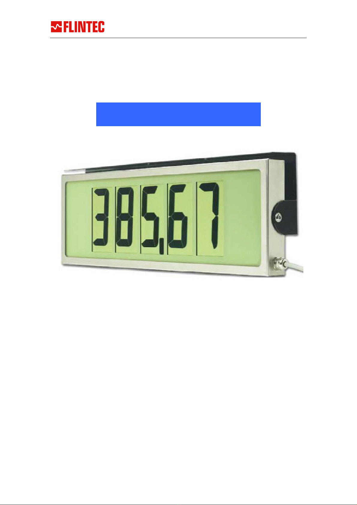
100 mm LCD Numerical Display
MANUAL
Release 20.07.2007
This manual was create with special care on the technical content an the correct
verbalisation. However, as a matter of principle Flintec GmbH will not take
responsibility for any amage cause by missing or wrong informations
FRD
–
100 BL

... the right weigh
FRD-100 BL Manual page 2 of 7
1. SAFETY INFORMATION ................................................................... 2
2. CHARACTERISTICS.......................................................................... 3
DISPLAY ........................................................................................................... 3
MECHANICAL .................................................................................................... 3
ELECTRONICS ................................................................................................... 3
CABLE ASSIGNEMENT ........................................................................................ 4
3. OPERATION NOTES ......................................................................... 4
INSTALLATION NOTES....................................................................................... 4
NORMAL BEHAVIOUR......................................................................................... 5
STANDARD DATA PROTOCOL DESCRIPTION........................................................ 5
4. SER ICE AND CONTACT INFORMATION......................................... 7
1. Safety Information
All pro ucts of this series are evelope , manufacture an teste in accor ance with
the applicable in ustry safety stan ar s. If these pro ucts are properly installe ,
operate an maintaine accor ing to the applicable technical instructions, rawings
an specifications, no hazar exists in the normal an inten e use of these pro ucts.
General Safety Guidelines
The following general safety gui elines apply to all Flintec - pro ucts:
All applicable safety and accident prevention recommendations must be
observed (VDE 0100 and VDE 0113).
All installation, start-up and maintenance work must be carried out by qualified
service personnel only.
An easily accessible power outlet must be located close by for devices equipped
with a main power cord and plug.
An easily accessible MAIN POWER ON/OFF switch must be provided for
equipment with permanent electrical connections.

... the right weigh
FRD-100 BL Manual page 3 of 7
2. Characteristics
DISPLAY
Character Height 100 mm
Number of igits 5
Resolution 7 segments plus colon an ecimal point
Technology Transflective positive TN LCD
Backlight Yes; Amber LED
MECHANICAL
Size casing 540 mm x 169 mm x 35 mm (w x h x ) (w/o connector)
Size inc. bracket 550 mm x 180 mm x 58 mm (w x h x ) (w/o connector)
Materials Stainless Steel 316
Protection IP-65
Weight 4,5 kg net
Display Dimensions
ELECTRONICS
Interface fiel selectable/autosearch: RS-232, RS-485 an 20 mA TTY
Current Loop
Data Format 300-38400 Bau with 7 or 8 atabits even, o or no parity
(Default: 9600, 7, Even)
Power requirements 9V DC (without backlight) - 24V DC (with backlight)
(typically power consumption <=100 mA)
Connection Unterminate 4m cable
... the right weigh
FRD-100 BL Manual page 4 of 7
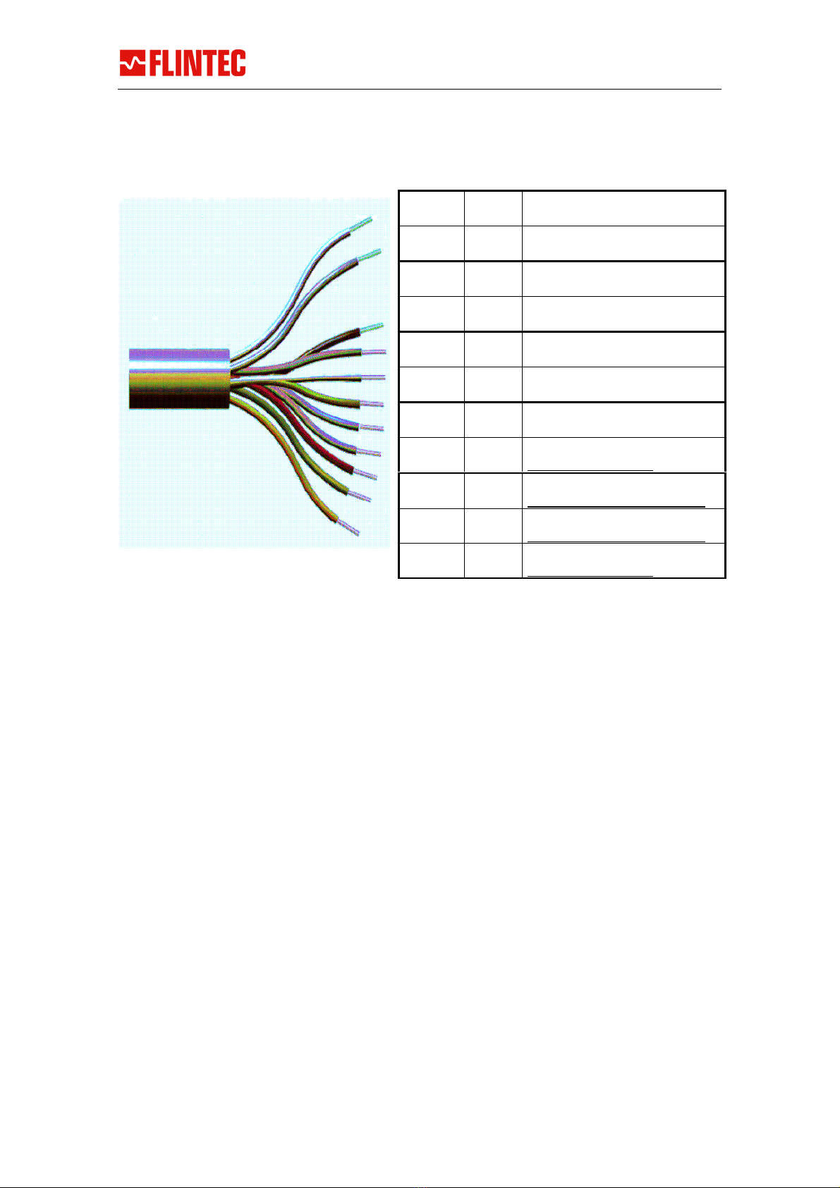
CABLE ASSIGNEMENT
* Note that RS-485 signals are eactivate internally to avoi picking up noise.
To activate RS485/422 you have to open the compartment on the back using Torx TX-
25 for the M4x10 screws, connect the Black an the Violet lea s to terminals A+ an
B- respectively
3. Operation Notes
INSTALLATION NOTES
To comply with various safety an conformance rulings, the system must be properly
groun e . The Scoreboar itself nee s to be connecte to safety earth, an the
connector shoul be firmly mate an fixe by use of fixing screws.
When power is applie , the isplay shoul respon by a sequence of control messages
(see „Normal Behaviour“). After the short start-up formality, isplay is blanke . If this
sequence is missing, check power source an connections. The voltage present at the
pins on the Scoreboar D-sub shoul be stable between 8 an 28 V c.
Pink +V DC External Power Supply +
Grey GND External Power supply –
*Black A+ RS-485/422 Transciever
*Violet B- RS-485/422 Transciever
White TTY+ Input positive 20 mA
Brown TTY- Input negative 20 mA
Blue RxD RS232 Input from TxD of Host
Re /Blue
RxD
GND
RS232 Signal Groun
(Short it with GREY)
Re TxD RS232 Output to RxD of Host
(Not nee e for normal use)
Green +O + Output
(Not nee e for normal use)
Yellow -O - Output
(Short it with GREY)

... the right weigh
FRD-100 BL Manual page 5 of 7
NORMAL BEHA IOUR
When power is applie , the Scoreboar will go through a sequence of initialisation. By
carefully looking at the isplay, you will be presente the following ata:
888888 all segments are on, then off to verify correct operations
08.25 is the firmware version
A.00 is the a ress of the isplay (normally set to 00 if isable )
C:9600 in icates the current bau rate setting
P: 20 Protocol number or other i entification
After initialisation, the Scoreboar will blank with all ecimal points activate . This is
the efault 'waiting screen' in icating that it is awaiting a vali message.
The Display is set to “Autosearch” by stan ar . It will try to etect the connection an
ata protocol settings by itself. This etection is shown on the screen an can take
some minutes. After the settings were foun the isplay shoul show the incoming
ata on screen. (e.g. the weight sent out by the in icator)
If the screen is still empty after 5 minutes, please eactivate everything, check again
the cables an the in icator interface settings an restart everything.
Note that re ucing the voltage supplie below 20V will turn off backlight an re uce
current consumption. The operation will otherwise be as normal.
STANDARD DATA PROTOCOL DESCRIPTION
As a serial isplay, the message format han le is base on the parameter setting that
efines vali an essential ata. The ata isplaye is replace each time a vali new
message is receive . The timeout function may auto blank the isplay after a preset
number of secon s.
There are a lot of pre efine protocols store in the Display. The autosearch will
automatically set the correct one (if existing) to fit the incoming Data
The following text only escribes the factory efault protocol.
Default Protocol
<STX> ata<CR>
Where <STX>=ASCII 02 , <CR>=ASCII 13 . Data inclu es minus sign (-), ecimal
point (represente by '.' or',') an lea ing blanks or zeros.
Addressing Control
<SOH> AA <STX>
Will select isplay AA (00 to 99). 00 will broa cast to all connecte isplays.
A ressing is use relatively sel om
.
... the right weigh
FRD-100 BL Manual page 6 of 7
EC – Declaration of Conformity
Flintec GmbH
Bemannsbruch 9
D-74909 Meckesheim
The following named product:
FRD-100 BL Display
is conform to the following european directives and standards:
EN55011, EN50082 (Part 1 and 2) and CENELEC EN 60742
Meckesheim, 1.3.2001
Gerhard K. Adam
Geschäftsführer

... the right weigh
FRD-100 BL Manual page 7 of 7
4. SER ICE AND CONTACT INFORMATION
Flintec GmbH
Bemannsbruch 9
74909 Meckesheim
Germany
Tel.:+49 6226 9240 0
Fax :+49 6226 9240 99
http://www.flintec.com
Table of contents
Other Flintec Monitor manuals


