Flintec FRD-57 User manual

FRD-57
Remote Display LED
Technical Manual
Flintec GmbH
Bemannsbruch 9
74909 Meckesheim
GERMANY
www.flintec.com

FRD-57 Remote Display LED, Technical Manual Rev.2.1, October 2018 Page 1 of 8
Table Of Contents
1SAFETY INSTRUCTIONS................................................................................... 2
2Introduction.......................................................................................................... 3
3Specifications....................................................................................................... 3
4Installation............................................................................................................ 4
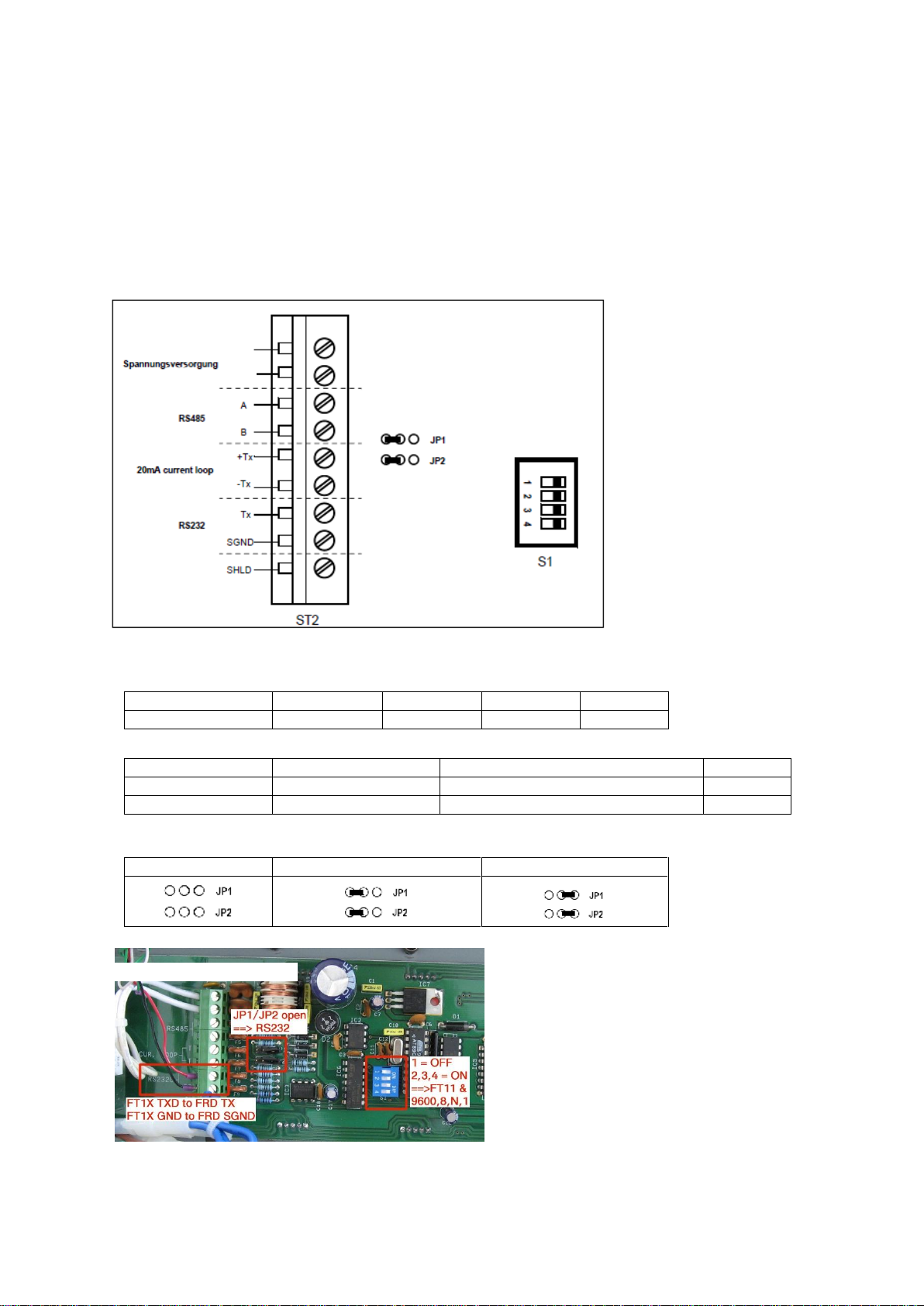
5Electrical Connections.......................................................................................... 4
6Connection Examples.......................................................................................... 5
6.1 FRD-57 and FT-1x / FT-10 / FT-11x.............................................................. 5
6.2 FRD-57 and DAD14x.x / DAS72.1 / LDUxx.x................................................ 5
7Dimensions.......................................................................................................... 6
RIGHTS AND LIABILITIES
All rights reserved.
No part of this publication may be reproduced, stored in a retrieval system, or transmitted in any form or by any
means, mechanical, photocopying, recording, or otherwise, without the prior written permission of FLINTEC
GmbH.
No patent liability is assumed with respect to the use of the information contained herein. While every precaution
has been taken in the preparation of this book, FLINTEC assumes no responsibility for errors or omissions.
Neither is any liability assumed for damages resulting from the use of the information contained herein.
The information herein is believed to be both accurate and reliable. FLINTEC, however, would be obliged to be
informed if any errors occur. FLINTEC cannot accept any liability for direct or indirect damages resulting from the
use of this manual.
FLINTEC reserves the right to revise this manual and alter its content without notification at any time.
Neither FLINTEC nor its affiliates shall be liable to the purchaser of this product or third parties for damages,
losses, costs, or expenses incurred by purchaser or third parties as a result of: accident, misuse, or abuse of this
product or unauthorized modifications, repairs, or alterations to this product, or failure to strictly comply with
FLINTEC operating and maintenance instructions.
FLINTEC shall not be liable against any damages or problems arising from the use of any options or any
consumable products other than those designated as Original FLINTEC Products.
NOTICE: The contents of this manual are subject to change without notice.
Copyright © 2013 by FLINTEC GmbH, 74909 Meckesheim, Bemannsbruch 9, Germany

FRD-57 Remote Display LED, Technical Manual Rev.2.1, October 2018 Page 2 of 8
1 SAFETY INSTRUCTIONS
CAUTION! READ THIS MANUAL BEFORE OPERATING OR SERVICING THIS
EQUIPMENT. FOLLOW THESE INSTRUCTIONS CAREFULLY. SAVE THIS MANUAL
FOR FUTURE REFERENCE. DO NOT ALLOW UNTRAINED PERSONNEL TO
OPERATE, CLEAN, INSPECT, MAINTAIN, SERVICE, OR TAMPER WITH THIS
EQUIPMENT. ALWAYS DISCONNECT THIS EQUIPMENT FROM THE POWER
SOURCE BEFORE CLEANING OR PERFORMING MAINTENANCE. CALL FLINTEC
ENGINEERING FOR PARTS, INFORMATION, AND SERVICE.
WARNING! ONLY PERMIT QUALIFIED PERSONNEL TO SERVICE THIS
EQUIPMENT. EXERCISE CARE WHEN MAKING CHECKS, TESTS AND
ADJUSTMENTS THAT MUST BE MADE WITH POWER ON. FAILING TO OBSERVE
THESE PRECAUTIONS CAN RESULT IN BODILY HARM.
WARNING! FOR CONTINUED PROTECTION AGAINST SHOCK HAZARD
CONNECT TO PROPERLY GROUNDED OUTLET ONLY. DO NOT REMOVE THE
GROUND PRONG.
WARNING! DISCONNECT ALL POWER TO THIS UNIT BEFORE REMOVING ANY
CONNECTION, OPENING THE ENCLOSURE OR SERVICING.
WARNING! BEFORE CONNECTING/DISCONNECTING ANY INTERNAL
ELECTRONIC COMPONENTS OR INTERCONNECTING WIRING BETWEEN
ELECTRONIC EQUIPMENT ALWAYS REMOVE POWER AND WAIT AT LEAST
THIRTY (30) SECONDS BEFORE ANY CONNECTIONS OR DISCONNECTIONS ARE
MADE. FAILURE TO OBSERVE THESE PRECAUTIONS COULD RESULT IN
DAMAGE TO OR DESTRUCTION OF THE EQUIPMENT OR BODILY HARM.
CAUTION! OBSERVE PRECAUTIONS FOR HANDLING ELECTROSTATIC
SENSITIVE DEVICES.

FRD-57 Remote Display LED, Technical Manual Rev.2.1, October 2018 Page 3 of 8
2 Introduction
The Remote Display Type FRD-57 in the wall housing can be used in many weighing applications,
where good readability is required.
The following Flintec devices are supported:
- FT-1x, FT-10 und FT-11x
- FT-0x
- DAD72.1, DAD141.1
The remote display is characterized by low power consumption.
The device has very bright LEDs and wide reading angel, the 6 digits display is 57mm.
The communication can be chosen via serial port: RS232, RS485 or 20mA current loop.
The remote display is designed in a stainless-steel housing, IP65.
3 Specifications
Display
Display
6 digits, red LED-7-segments, 57 mm
Point
adjustable, between every digit
Polarity
minus sign
Memory
serial EEPROM
Communication
Serial Port
RS232, RS485, or 20mA current loop
Baud rate adjustable with DIP-switches: 1200, 2400, 9600, 19600 baud
Data Bits adjustable with DIP-switches
Power Supply
230 VAC; +/-20%; 50…60Hz
Power Consumption
max. 7W
Environment
Operation Temperature
-20°C…+50°C
Storage Temperature
-10°C…+70°C
Humidity
90% RH max, non-condensing
Enclosure
Material
Stainless steel
Protection Class
IP65
Dimensions:
365 x 130 x 75

FRD-57 Remote Display LED, Technical Manual Rev.2.1, October 2018 Page 4 of 8
4 Installation
Open the rear wall and choose the required connection. The serial connection can be established over
RS232, RS485 or 20mA current loop. Only one of the connections can be used at the same time. The
connections of the unused interfaces must not be connected.
There are two jumpers next to the connection terminal. These are used to select the serial interface.
The communication parameters of the selected interface can be changed via S1 DIP-switch
5 Electrical Connections
Figure 1
Settings DIP Switch (S1)
Baud rate
1200
2400
9600
19200
Dip SW (on)
---
1
2
1,2
Device
FT-1x, FT-10, FT-11x
FT-0x / LDU, DAD14x.x, DAS72.1
FT-0x
Data
N,8,1
N,8,1
E,7,1
Dip SW (on)
3, 4
3
---
Operation mode (Jumper JP1, JP 2)
RS-232
20mA cur.Loop
RS-485
Figure 2

FRD-57 Remote Display LED, Technical Manual Rev.2.1, October 2018 Page 5 of 8
6 Connection Examples
6.1 FRD-57 and FT-1x / FT-10 / FT-11x
•Operation port: RS232
•DIP Switch S1 (ON): 2, 3, 4 (=9600, 8N1)
•Jumper:
•PIN connection:
•FT-1x and FT-11x Settings for RS232 Port
Parameter FT-1x
Parameter FT-10
Parameter FT-11x
Explanation
[000 1]
[000 1]
[111 CONST]
Continuously
[001 3]
[001 3]
[112 9600]
9600 Baud
[002 0]
---
---
No Handshake
[003 00]
[003 00]
[119 00]
Adres 0
[004 0]
[004 0]
[113 8]; [114 NO]
8, N, 1
[005 1]
[005 1]
[115 NO]
Check sum
---
[0061]
---
Carriage return
---
[0070]
---
Line Feed
6.2 FRD-57 and DAD14x.x / DAS72.1 / LDUxx.x
•Operation port: RS485
•DIP Switch S1 (ON): 2, 3 (=9600, 8N1)
•Jumper:
•PIN connection:
•DAD14x.x; DAS72.1, LDUxx.x Settings for RS485 Port
Parameter
Explanation
Baud rate
9600
Ser. Port
485
Adres
0
FT-1x, FT-10,
FT-11x
Signal
FRD-57
Pin 2
TxD
Tx
Pin 7
GND
SGND
DAS, DAD, LDU
72.1, 14x.x, xx.x
Signal
FRD-57
Tx+
Tx+
A
Tx-
Tx-
B

FRD-57 Remote Display LED, Technical Manual Rev.2.1, October 2018 Page 6 of 8
7 Dimensions
Table of contents
Other Flintec Monitor manuals