Fluke Biomedical WiFi Connector User manual

PN 4766241 April 2016, Rev. 1
©2016 Fluke Corporation. All rights reserved.
Specifications are subject to change without notification.
All product names are trademarks of their respective companies.
WiFi Connector
Instructions
Introduction
The WiFi Connector (the Product or Connector) makes a wireless connection
between Fluke Biomedical instruments and a PC with Ansur Software.
If the Ansur version on the PC is not 3.1 or later, then download the latest
Ansur software from: www.flukebiomedical.com.
Safety
A Warning identifies hazardous conditions and actions that could cause
bodily harm or death. A Caution identifies conditions and actions that could
damage the Product, the equipment under test, or cause permanent loss of
data.
XWWarning
To prevent possible electrical shock, fire or personal injury,
follow these guidelines:
• Read all safety information before you use the Product.
• Carefully read all instructions.
• Use the Product only as specified, or the protection supplied
by the Product can be compromised.
• Do not use the Product around explosive gas, vapor, or in
damp or wet environments.
• Do not use the Product if it operates incorrectly.
• Use this Product indoors only.
• Use only current probes, test leads, and adapters supplied
with the Product.
• Do not put metal objects into connectors.
• Disconnect the battery charger and move the Product or
battery to a cool, non-flammable location if the rechargeable
battery becomes hot (>50 °C) during the charge period.
• Replace the rechargeable battery after 5 years of moderate
use or 2 years of heavy use. Moderate use is defined as
recharged twice a week. Heavy use is defined as discharged
to cutoff and recharged daily.

2
Table 1 shows the symbols used on the Product and in this document.
Unpack the Connector
Carefully unpack all items from the box and check that you have the items in
Table 2.
Table 1. Symbols
Symbol Description
WWARNING. RISK OF DANGER.
Consult user documentation
This product contains a lithium-ion battery.
)Certified by CSA Group to North American safety
standards.
Conforms to relevant Australian Safety and EMC
standards.
~
This product complies with the WEEE Directive
marking requirements. The affixed label indicates
that you must not discard this electrical/electronic
product in domestic household waste. Product
Category: With reference to the equipment types in
the WEEE Directive Annex I, this product is classed
as category 9 "Monitoring and Control
Instrumentation" product. Do not dispose of this
product as unsorted municipal waste.
Table 2. Replaceable Parts
Item Fluke Biomedical Part
Number
Strap 669960
Magnet 669952
Power Supply 4724645
Bluetooth dongle (optional) 4699703
CD with Utility 4777173
3
Setup the Connector
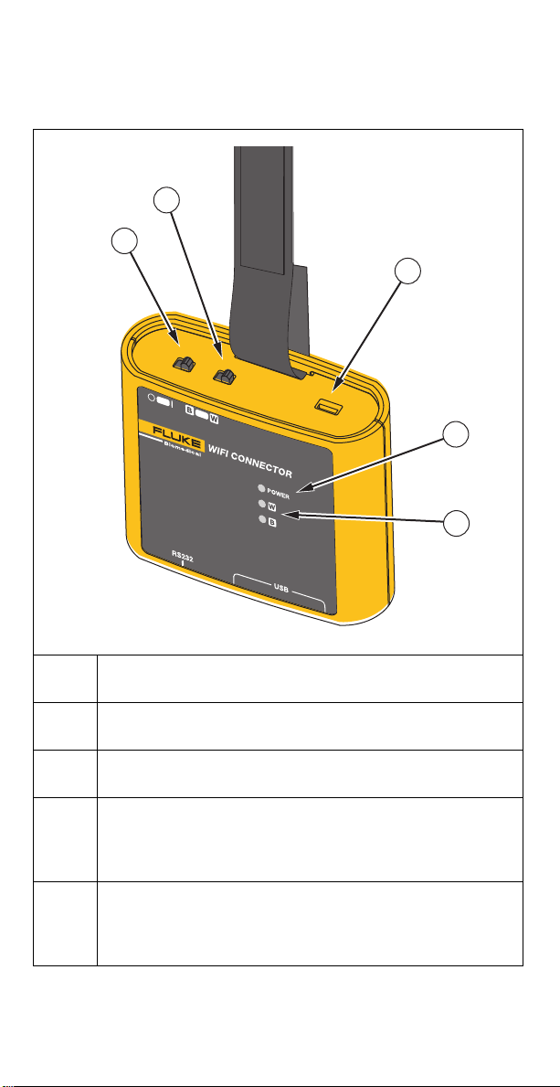
Table 3 shows the indicators and controls on the Connector.
Table 3. Product Indicators
Power switch
Selector for the type of wireless connectivity: B–802.15.1 or W–WiFi
USB port (micro B) for charging and upgrading firmware
Power indicator:
Flashing green – the Connector is on and not fully charged
Solid green – the Connector is fully charged
Wireless indicators: B- 802.15.1 and W- WiFi,
Flashing green – the Connector is waiting for a connection
Solid green – the connection is stable (on or off)
1
2
3
4
5
4
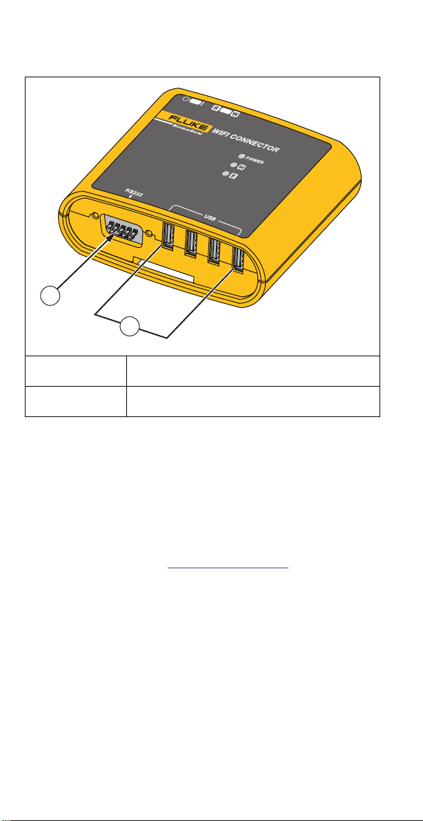
Table 4 shows the connections for Fluke Biomedical devices.
Charge the Connector
You must charge the batteries prior to the first use. Always use the correct
charger and follow the charging instructions. To charge the Connector, attach the
USB cable to the Connector and to a charging port on the PC or to the power
adapter provided and turn on the Connector.
Install the Connector Application
Before you use the Connector, set up the WiFi Connector Utility (the App) on the
PC.
1. Download the App from www.flukebiomedical.com.
2. Browse to the installation folder and double-click Setup.exe.
3. Follow the on-screen instructions to install the application.
When the installation is complete, a message appears and the icon for
the App shows on the desktop.
Table 4. Product Connectors
RS-232 port
USB ports (type A)
1
2

5
Wireless Communication Setup
Use the App to view or change settings for the Connector.
Note
For best results make sure the battery is charged before you configure
or load software on the Connector. If necessary, temporarily disconnect
or disable wireless devices that interfere with the setup.
1. Use the USB cable to attach the Connector to the PC.
2. On the Connector:
a. Set the Wireless Connectivity to Wor B.
b. Turn on the Connector.
Wait until the indicator (W or B) flashes.
3. On the PC:
a. Double-click the App icon.
The status shows in the bottom of the App window.
b. When the status shows as Connected, click CONFIGURE.
To configure 802.15.1 communications, click 802.15.1 Settings.
Make a note of the Device name and Device PIN (Device PIN is
the pairing code). Follow the instructions in 802.15.1
Communications.
To configure WiFi, communications, click WiFi Settings. Make a
note of the WiFi SSID and the Password. Follow the instructions in
WiFi Communications.
802.15.1 Communications
Note
Instructions may vary for different versions of Windows.
1. If the PC has built-in Bluetooth communication, make sure it is turned
ON and enabled.
If the PC does not have built-in communication, insert the 802.15.1
dongle into the PC.
Note
For best results use the dongle available from Fluke.
2. Click in the notification area or go to the Control Panel and select
Devices and Printers.
3. Click Add a Device.
4. Select the device name for the Connector and click Next.
5. Select the option to add the device using a pairing code.
6. At the prompt for the pairing code, enter the Device PIN and click Next.
7. At the confirmation message, click Close.

6
WiFi Communications
Note
Instructions may vary for different versions of Windows.
1. If the PC does not have built-in WiFi:
a. Connect a WiFi dongle to the PC and install the drivers.
b. Right-click the network icon on the desktop tool bar and select
Open Network and Sharing Center > Change Adapter Settings
then right-click the WiFi adapter and make sure the adapter is
enabled.
2. Right-click the network icon on the desktop toolbar or from the Control
Panel and select Open Network and Sharing Center > Manage wireless
networks or Setup a new connection or network > Manually connect
to a wireless network.
3. Make these settings:
Connect a Device to Ansur
1. Turn on the Connector.
Wait for the power indicator to show solid green.
2. Attach the Fluke Biomedical instrument to the Connector with a USB cable
or an RS-232 cable.
Note
The Connector can support only one VT305 connection at a time.
3. Use Ansur to communicate to the device through the Connector.
Note
If the Connector is added and paired with the PC, the Connector is
listed on the Devices and Printers in the Control Panel.
Field Procedure
Network name The SSID of the Connector.
Security type Select WPA2-Personal.
Encryption type Leave AES selected.
Security key The password for the Connector

7
Upgrade the Connector Firmware
Note
For best results, make sure the battery is charged before you configure
or load software on the Connector.
1. On the PC, download the latest firmware from www.flukebiomedical.com.
2. Use the USB cable to attach the Connector to the PC.
3. Turn on the Connector.
4. On the PC, double-click the App icon.
a. Click FIRMWARE UPGRADE.
b. Click Start Upgrade.
c. Browse to the latest firmware file.
d. Click Upgrade.
Keep the device connected until the load completes.
5. Turn off the Connector, then turn on the Connector.
Maintenance
XWWarning
To prevent possible electrical shock, fire or personal injury, follow
these guidelines:
• Repair the Product before use if the battery leaks.
• Be sure that the battery polarity is correct to prevent battery
leakage.
• Use only Fluke approved power adapters to charge the battery.
• Batteries contain hazardous chemicals that can cause burns or
explode. If exposure to chemicals occurs, clean with water and
get medical aid.
• Do not disassemble the battery.
• Do not disassemble or crush battery cells and battery packs.
• Do not put battery cells and battery packs near heat or fire. Do
not put in sunlight.
• Do not short the battery terminals together.
• Do not keep cells or batteries in a container where the terminals
can be shorted.
• Do not operate the Product with covers removed or the case
open. Hazardous voltage exposure is possible.
• Remove the input signals before you clean the Product.
• Use only specified replacement parts.
• Have an approved technician repair the Product.

8
Troubleshoot the Connector
After troubleshooting or maintenance, restart the Connector and make sure that
it starts without errors. Table 5 explains possible resolutions.
Table 5. Troubleshoot the Connector
Problem Resolution
Connector cannot communicate
with the PC
Make sure you used the Device PIN or WiFi
password to pair the Connector to the PC.
Increase the baud rate of the test
instrument for Ansur communication. The
baud rate should be 2400 or higher.
PC automatically connects to a
different WiFi
Disable auto-connect for other WiFi
connections.

9
Specifications
Temperature
Operating ........................................... 10 °C to 40 °C (50 °F to 104 °F)
Storage............................................... -20 °C to 60 °C (-4 °F to 140 °F)
Humidity ............................................. 10 % to 90 % non-condensing
Altitude ................................................... 2000 m
Ingress Protection Rating....................... IP-20
Weight .................................................... 0.2 kg (0.5 lb)
Size ........................................................ 9 cm x 7 cm x 3 cm
Rechargeable lithium-ion battery,
internal.................................................... 3.7 V, 2.2 Ah, 8.2 Wh, 1 IPC6/65/66
Safety ..................................................... IEC 61010-1:Pollution Degree 2
Electromagnetic Compatibility (EMC)
International ...................................... IEC 61326-1: Basic
Emissions Classification..................... IEC CISPR11: Group 2, Class A.
Group 2 Equipment contains ISM RF equipment in which radio-
frequency energy in the frequency range 9 kHz to 400 GHz is
intentionally generated and used or only used, in the form
of electromagnetic radiation, inductive and/or capacitive coupling, for
the treatment of material or inspection/analysis purposes.
Class A equipment is suitable for use in nondomestic locations and/or
directly connected to a low voltage power supply network.
USA (FCC)......................................... Intentional Radiators
This device complies with part 15 of the FCC Rules. Operation is
subject to the following two conditions: (1) This device may not cause
harmful interference, and (2) this device must accept any interference
received, including interference that may cause undesired
operation.(15.19) Changes or modifications not expressly approved by
Fluke could void the user’s authority to operate the equipment. (15.21)
Wireless Module Listing
FCC (United States) compliant
(Class A) ............................................ FCC ID: X3ZBTMOD3
IC (Industry Canada)
compliant............................................ IC: 8828A-MOD3
CE (European) certified...................... CE0051
802.15.1 qualified............................... QD ID: B019224
Wireless Radio
Frequency range................................ 2412 MHz to 2483 MHz
Output Power ..................................... 10 mW

10
Warranty and Product Support
Fluke Biomedical warrants this instrument against defects in materials and
workmanship for one year from the date of original purchase. During the
warranty period, we will repair or at our option replace, at no charge, a
product that proves to be defective, provided you return the product, shipping
prepaid, to Fluke Biomedical. This warranty covers the original purchaser
only and is not transferable. The warranty does not apply if the product has
been damaged by accident or misuse or has been serviced or modified by
anyone other than an authorized Fluke Biomedical service facility. NO
OTHER WARRANTIES, SUCH AS FITNESS FOR A PARTICULAR
PURPOSE, ARE EXPRESSED OR IMPLIED. FLUKE SHALL NOT BE
LIABLE FOR ANY SPECIAL, INDIRECT, INCIDENTAL OR
CONSEQUENTIAL DAMAGES OR LOSSES, INCLUDING LOSS OF DATA,
ARISING FROM ANY CAUSE OR THEORY.
This warranty covers only serialized products and their accessory items that
bear a distinct serial number tag. Recalibration of instruments is not covered
under the warranty
This warranty gives you specific legal rights and you may also have other
rights that vary in different jurisdictions. Since some jurisdictions do not allow
the exclusion or limitation of an implied warranty or of incidental or
consequential damages, this limitation of liability may not apply to you. If any
provision of this warranty is held invalid or unenforceable by a court or other
decision-maker of competent jurisdiction, such holding will not affect the
validity or enforceability of any other provision.
7/07
Fluke Biomedical
6920 Seaway Blvd.
Everett, WA, 98203
U.S.A.
To find the nearest service center, go to www.flukebiomedical.com/service or:
In the U.S.A. and Asia: In Europe, Middle East, and Africa:
Cleveland Calibration Lab
Tel: 1-800-850-4608 x2564
Email:
Eindhoven Calibration Lab
Tel: +31-40-2675300
Email: [email protected]
Table of contents


