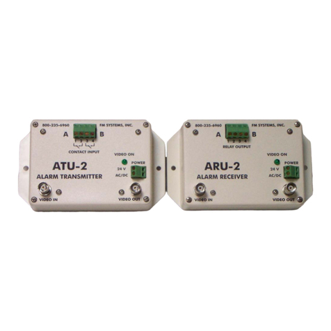
FM Systems ATU-2HD User manual

ATU-2HD \ ARU-2HD
RELAYTRANSMITTER\ RECEIVERUNIT
INSTRUCTION BOOK
IB6484-01
9-20-2019

TABLE OF CONTENTS
DESCRIPTION 2
MOUNTING INSTRUCTIONS 3
HOW TO CABLE THE ATU-2HD 3
HOW TO CABLE THE ARU-2HD 3
POWER SUPPLY INSTALLATION 3
SET-UP OF THE ATU-2HD AND ARU-2HD 4
OPERATION 4
CARE AND MAINTENANCE 4
SETUP LINE & VIDEO FORMAT 5
APPLICATIONS (WHERE TO USE THE SYSTEM) 6
TROUBLE SHOOTING THE INSTALLATION 6
ATU-2HDisb Page 1 of 7

DESCRIPTION
These devices transmit and receive relay and contact control
signals encoded on all 26 HD and SD video formats like HD-TVI, HD-CVI,
AHD, NTSC, and PAL video coaxial cable. You can insert your contact
relay, alarm, and control signals anywhere a video signal is being used
on Unshielded Twisted Pair wire (UTP) or Coaxial cable. Two relay
control input signals are inserted onto one line of the vertical
interval of the video and will travel over any distance the video
signal can go. One of the contacts can be used as a signal integrity
alarm for complete signal security.
The ATU-2HD RELAY TRANSMITTING UNIT and the ARU-2HD RELAY
RECEIVING UNIT used together create a two channel, alarm relay control,
or remote-control system.
Both units have a DIP Switch for line selection signal insertion
control and video mode selection. By selecting different lines of
operation, you can provide up to 8 control signals by installing
additional units in series with the video signal. The DIP switch is
also used to select the type of video you want to use. You can s elect
HD-TVI, HD-CVI, AHD, NTSC, CVBS, and PAL video formats.
The relay control signals are inserted onto the Vertical Interval
of the video signal and will not interfere with the image.
One channel may be used as a system alarm that will operate upon
loss of power to either terminal or loss of transmission path (coax
cable cut). In the event of power failure to the ATU-2HD or ARU-2HD the
video thru-put will not be interrupted. This loop-through method allows
you to place the transmitter/receiver pair at either end, so you can
send the signals in either direction. Also, if you use two sets of
units, you can send relay contact control in both directions at the
same time on any coaxial or twisted wire path.
For a gate camera you can put a button at the gate to ring a bell
and then send a switch control for a relay to open the gate going in
the other direction all on the same video signal without having to run
additional wires.
Contact closures to the ATU-2HD input will be repeated as relay
closures at the ARU-2HD output.
The system is housed in a bone colored ABS enclosure that has a UL
flame rating of 94-VO and is powered by any 12 VAC or VDC power supply,
a 12 VDC is supplied with the units. The system has a power on, video
on LED for installation and trouble shooting of the video system. When
power is on and video is not connected the LED will flash on and off to
indicate a video loss has occurred.
ATU-2HDisb PAGE 2 OF 7

MOUNTING INSTRUCTIONS
The rugged one-piece mounting structure allows you to mount the
unit firmly in place with two screws. Select a place to mount the unit
away from harsh or wet environments, indoors is recommended. The ATU-
2HD should be located near your originating contact signals and the
ARU-2HD should be near your alarm panel or the place you wish to bring
the relay signals to. Select a position that gives you the best access
to cable the system and one that reduces the labor in installation.
HOW TO CABLE THE ATU-2HD
Connect the video cable you wish to use from the camera to the
"VIDEO IN" BNC connector and connect the cable going to the ARU-2HD to
the "VIDEO OUT" BNC connector. It is not necessary for power to be on
at this time, the video path will only be interrupted during the cable
attachment. This system will function with HD-TVI, HD-CVI, AHD, CVBS,
NTSC, and PAL video types. Next attach the alarm or control wires for
each station to the green connector block marked A and B. Each pair of
screw terminals marked A and B are LOOP inputs. Attach your Dry Contact
Closures or switches to these screw terminals. The current for loop
sensing is built into the ATU-2HD. Do not connect TTL signals to these
connectors.
HOW TO CABLE THE ARU-2HD
Connect the video cable you are using to the "VIDEO IN" BNC on the
ARU-2HD and the "VIDEO OUT" BNC goes to the monitor, recorder or other
video equipment. BE SURE TO TERMINATE THE END OF THE VIDEO CABLE WITH A
75 OHM TERMINATION OR PROPERLY TERMINATED INTO OTHER EQUIPMENT. Next
attach the alarm or control wires for each station to the green
connector block marked A and B. These relay output wires can go to your
alarm panel or control device. Each pair of screw terminals marked A
and B are relay contact closures outputs. The outputs from connector
block A and B will duplicate the input signals from the ATU-2HD inputs.
A contact closure at A of the ATU-2HD will result in a contact closure
at A of the ARU-2HD and the same for the B channel.
POWER SUPPLY INSTALLATION
The ATU-2HD and ARU-2HD are powered by two 12 Volt AC or DC wall
mount power transformers, 12VDC are included with the units. Connect
the 12 VDC power transformer to the Green terminal block marked 12VDC.
The ATU-2HD can be powered by power sources as low as 9 volts AC or DC.
However, the ARU-2HD must be operated with 12 Volts AC or DC.
Connect the power source and you will see the Green LED turn on to
indicated power up, it will be on, or it will be flashing on and off,
depending on the video status. Power on with no video will cause the
LED to light up and flash on and off. Power on with video input will
cause the LED to light up fully.
ATU-2HDisb PAGE 3 OF 7

SET-UP OF THE ATU-2HD AND ARU-2HD
Both units can operate on a maximum of 4 separate line channels
allowing up to four sets of ATU/ARU-2HD units to be used on any HD-TVI,
HD-CVI, or AHD video source and on CVBS, NTSC, and PAL up to a maximum
of two sets of ATU/ARU-2HD units can be used due to the limited number
of lines (see the table on page 5). The units are shipped on the
standard channel 1 for HD-TVI 720P (25fps) video format. If you wish to
use the units on a different channel or wish to operate more than one
unit on the same video signal, then it is necessary to program the new
channel using the DIP switch on the PC Board.
Programming a new channel is done with switch 1-2 of the 8
position DIP switch on the inside of the box. Open the box by removing
the 4 screws in the outer most corners of the box. Open the lid and
look for the Blue 8 position DIP switch.
The first 2 switches 1-2 are for line selection, switches 3-7 are
for selecting the video mode or type of video, switch 8 is not used.
Select the channel you wish to operate on 1-2 and select the video
format using switch numbers 3-7. You must select the same channel and
video format for both ATU-2HD and ARU-2HD so they will work together.
As many as 4 ATU-2HD and ARU-2HD units can be used on the same
video signal by programming them to different channels. When the ARU-
2HD is on the same channel as an ATU-2HD with the power applied and the
video on the Green LED on both units will stop flashing and stay on.
This indicates that the video is being received.
OPERATION
When the units have been installed and programmed for the correct
video source you will see that when a contact on the ATU-2HD is closed
a relay in the ARU-2HD closes in response. Through the video\data path
the contact sense is relayed to the alarm panel or other equipment
directly. If the power on the equipment is remove or turned off the
video path will not be obstructed by either the ATU-2HD or ARU-2HD
units.
If the power is turned off on the ARU-2HD then both relays will
open regardless of the position of the ATU-2HD input contacts. If a
system alarm is desired to indicate a loss of communication between the
ATU-2HD and the ARU-2HD, one of the contacts at the ATU-2HD can be
wired closed then that contact will serve as a system alarm channel.
This contact will open if power is turned off on either unit or if the
video path between the two units is interrupted.
CARE AND MAINTENANCE
There is no routine maintenance or calibration required with this
equipment. There are no adjustments required inside the box. Open the
box only to choose the desired operating channel and video mode.
ATU-2HDisb PAGE 4 OF 7

SETUP LINE & VIDEO FORMAT
When you change one of the switch settings, the switch is read and
the unit changes the channel or video mode immediately. Also, in the
case of a power or video interruption the unit reads the switches and
resets the controls to operate as selected. ON is switch up toward the
“ON”marking, and OFF is down toward the number side and X means
doesn’t care.
CHANNEL LINE SELECTOR
SW 1 2
1 ON ON LINE 3-4
2OFF ON LINE 7-8
3 ON OFF LINE 11-12
4OFF OFF LINE 15-16
VIDEO MODE SELECTOR
SW 3 4 5 6 7 8
1 ON ON ON ON ON X TVI 720P 25fps
2OFF ON ON ON ON X TVI 720P 30fps
3 ON OFF ON ON ON X TVI 1080P 25fps
4OFF OFF ON ON ON X TVI 1080P 30fps
5 ON ON OFF ON ON X TVI 4MP 15fps
6OFF ON OFF ON ON X TVI 4MP 25fps
7 ON OFF OFF ON ON X TVI 4MP 30fps
8OFF OFF OFF ON ON X TVI 5MP 12.5fps
9ON ON ON OFF ON X TVI 5MP 20fps
10 OFF ON ON OFF ON X CVI 720P 25fps
11 ON OFF ON OFF ON X CVI 720P 30fps
12 OFF OFF ON OFF ON X CVI 1080P 25fps
13 ON ON OFF OFF ON X CVI 1080P 30fps
14 OFF ON OFF OFF ON X CVI 4MP 25fps
15 ON OFF OFF OFF ON X CVI 4MP 30fps
16 OFF OFF OFF OFF ON X AHD 720P 25fps
17 ON OFF ON ON OFF X AHD 720P 30fps
18 OFF ON ON ON OFF X AHD 1080P 25fps
19 ON ON ON ON OFF X AHD 4MP 15fps
20 OFF OFF ON ON OFF X AHD 4MP 25fps
21 ON OFF OFF ON OFF X AHD 4MP 30fps
22 OFF ON OFF ON OFF X AHD 5MP 12.5fps
23 ON ON OFF ON OFF X AHD 5MP 20fps
-- - - - - ---------------
24 ON OFF OFF OFF OFF X PAL 625L 50hZ
25 OFF OFF OFF OFF OFF X CVBS, NTSC 525L 60hZ
ATU-2HDisb PAGE 5 OF 7

APPLICATIONS (WHERE TO USE THE SYSTEM)
This system can be used anywhere that a video signal on coax cable
or twisted pair exists. Some uses are in a CCTV camera installation,
LASER OPTICAL transmission, STL microwave applications, Broadcast TV
transmissions, Cable TV, Relay, Alarm and Control and many other
applications. Relay control can be sent in either direction on the
video cable and both directions when two sets of units are used.
TROUBLESHOOTING THE INSTALLATION
When installing ATU-2HD and ARU-2HD units care must be taken to
assure that both units are set to the same channel and video mode or
standard for operation including (TVI,CVI,AHD ect), then determine the
number of line (720p, 1080P) ect, then determine the frames per second
or frame rate (12.5, 25, 30 ect. Then see the chart to determine the
correct switch settings. If all the switches are set the same on the
ATU-2HD and ARU-2HD units, they will operate on the same selected video
line and video mode or video format.
It is also important to select the proper format of video for
correct operation. Check with your cameras specifications for the video
type or format of the video source, be it HD-TVI, HD-CVI, AHD, PAL, or
CVBS (NTSC) the USA format for standard definition (SD) video. If you
experience the relays in the ARU-2HD chattering on and off, then it is
most likely that the Video Mode selector switches 3-7 are not set
correctly for the format of video being used.
If only one of the two relays operate then check the Line Selector
settings switches 1-2 and make sure they are set the same on both units
and make sure they are not set to a line that exceeds the maximum line
setting for the selected video format. Also, we have determined that
some HD cameras put signals in the first few lines of the vertical
interval to help balance the DC component of the video coming out of
the vertical interval. If you find that the relays on the receiver are
always on and the LEDs are always lit then select a different channel
of operation with DIP switches 1-2.
If you have no relay operation, then check for power at each unit
and make sure that the GREEN Power LED is on and not flashing. A
Flashing LED indicates no video input to the unit. When any format of
video is applied the Power LED will turn on solid and stop flashing.
If the relays turn on and off every few seconds, then check your
video signal for any ground loops. Ground loops can disrupt video
images and display horizontal bars, normally two on the screen at a
time moving up the screen slowly. If you have this condition, then lift
the camera side of the video cable off any local ground and use only
the DVR side of the system for the cable ground. Non powered balun
style ground loop blockers can also be used to remove the ground loops.
If your relay signal is going from the camera to the DVR the
signal generated in the ATU-2HD will pass through amplifiers and other
active (powered) devices and work fine. However, if you wish to pass
signals up the coaxial cable in the opposite direction from the flow of
the video signal you may not have any active (powered) equipment in the
path of the ATU-2HD units signals. Amplifiers will block the reverse
path from DVR to Camera for control.
ATU-2HDisb PAGE 6 OF 7

If amplifiers are used at the end of the line to boost the signal,
place our equipment ahead of the amplifiers so that our transmitter is
directly connected to our receiver by the coaxial cable with no
amplifier in between them.
Any amplifier that is placed between the ATU-2HD and the ARU-2HD
units in the reverse direction will block the signal from going
through. Passive (non-powered) equipment such as ground loop baluns are
allowed between the ATU-2HD and the ARU-2HD because they will pass the
signals in both directions with no blocking and function correctly. Any
equipment can be placed outside of the connection between the ATU-2HD
and the ARU-2HD units if the two units are directly connected to each
other with the cable or twisted pair wire (UTP).
If you still have intermittent operation of the relays or only one
relay operates then you have not selected the correct video mode on the
dip switch. If you cannot completely identify the video cameras type of
video it is possible to use the trial method to determine the video
standard you are working with. This equipment will work with all 24
types of HD video and both PAL and CVBS SD standards. To use the trial
method to set the dip switches do the following procedure.
Connect the Transmitter unit to the receiver unit and power them
both up. Connect the unknown camera format to the transmitter. It is
not necessary to connect the DVR but you must terminate the video
source with a 75 Ohm termination or connect the DVR to the receiver
output. Next put select all zeros on the 8 position DIP switch. Start
by turning the switch number 3 to ON, wait 5 seconds and see if both
contacts communicate reliably if not go to the next switch setting on
the switch table. They change in a binary progression. Be sure to wait
5 seconds between switch changes for the equipment to set up the new
format of operation. This method takes some time and it is better to
determine the correct video format from the specification sheets if
possible.
ATU-2HDisb PAGE 7 OF 7
This manual suits for next models
2
Table of contents
Other FM Systems Receiver manuals
